

Soundoff Signal nFORCE ENFSSS**-Single Series, nFORCE ENFDSS***-Dual Series Installation Instructions Manual
Page 1
1.800.338.7337 / www.soundoffsignal.com
1
ENFSLXSS 11.14
INSTALLATION:
SURFACE MOUNT
1) Establish a position on the vehicle. Use the
gasket (provided) as a template to drill 1/4”
diameter wire hole and pilot holes for mounting
screws. Note: pilot holes are 4.91” on center.
Caution: Do not stretch gasket as this may
change the required hole spacing.
SAE J595 CLASS 1 SURFACE MOUNTS
ENFSSS(XX)- SINGLE
ENFDSS(X)(XX) - DUAL
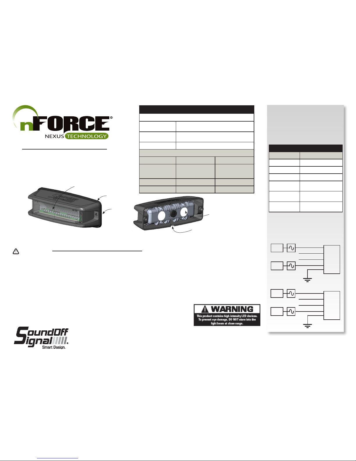
TECHNICAL SPECIFICATIONS
SURFACE MOUNT nFORCE
Single Mount
Dimensions:
5.0”L x 1.72”H x 1.50”D
Double Mount
Dimensions:
5.0”L x 3.13”H x 1.50”D
Input Voltage: 10 - 16 Vdc or 10 - 30 Vdc*
CURRENT CONSUMPTION
10-16 Vdc 10-30 Vdc *
6 LED Single
12 LED Dual &
18 LED Tri-Color
<1.0A @12.8 Vdc <0.6A @ 25.6 Vdc
9 LED Single Color <1.5A @ 12.8 Vdc <0.9A @ 25.6 Vdc
12 LED Single Color <2.0A @12.8 Vdc <1.2A @ 25.6 Vdc
* - Special Order
GASKET
HOUSING
LIGHT ASSEMBLY
SINGLE MOUNT VERSION - DOUBLE MOUNT
VERSION NOT SHOWN
BACK VIEW OF SINGLE SURFACE MOUNT SHOWN W/O
RUBBER MOUNTING GASKET
- TYPICAL FOR BOTH VERSIONS-
DO NOT DAMAGE, BLOCK OR
TOUCH THE BREATHER PATCHES
MAKE SURE DRAIN
HOLE IS FACING DOWN
NOTICE:
Installers and users must comply with all applicable federal, state and local laws regarding use and installation of warning devices.
Improper use or installation may void warranty coverage. To review our Limited Warranty Statement & Return Policy for this or any SoundOff Signal product, visit our website at
www.soundoffsignal.com/sales-support. If you have questions regarding this product, contact Technical Services, Monday - Friday, 8 a.m. to 5 p.m. at 1.800338.7337 (press #4 to skip the
automated message). Questions or comments that do not require immediate attention may be emailed to techservices@soundoffsignal.com.
SUPERIOR CUSTOMER RELATIONSHIPS. SMARTLY DESIGNED LIGHTING & ELECTRONIC SOLUTIONS.
•HIGH CURRENT interconnects must be properly terminated. Poor crimp quality can cause heat
build-up and fire. Follow crimp connector manufacturer instructions.
•DO NOT install this product or route any wires in the Air Bag Deployment Zone. Refer to vehicle
Owner’s Manual for deployment zones.
•Unit may become hot to touch during normal operation.
•Failure to properly install connectors, fuses or wiring may cause vehicle failure or fire.
•Installation must only be performed by trained technician. Installer must determine vehicle wiring
configuration and proper integration of system.
•Use proper wire gauge. All power wires connecting to positive (+) or negative (-) battery terminal
or local chassis ground (-) must be sized to supply at least 125% of max. current and properly fused at
power source.
•Install protective grommets when routing wire through firewall or metal.
WARNING
WIRE HOOK-UP TABLE
WIRE COLOR: FUNCTION:
ORANGE OR RED Power
BLACK Ground
BLUE OR GREEN** Sync2 *
YELLOW OR WHITE
to GROUND
Wire Function
-See page 4-
YELLOR OR WHITE
to POWER
Function Wire
RED/WHITE OR
ORANGE/WHITE
Power
** To sync multiple nFORCE lights, connect
the Green and/or Blue wires from each light
together.
* Will NOT work w/ other sync products
such as Ghost, LED3, & Intersector.
BLACK
RED
WHITE
GREEN
SINGLE OR DUAL
LIGHT HEAD 1
BLACK
BLUE
ORANGE
YELLOW
DUAL
LIGHT HEAD 2
Sync
Set-up/Function
Sync
Set-up/Function
RED/WHITE
ORANGE/WHITE
+Vdc
A FUSE
5
+Vdc
+Vdc
A FUSE
5
+Vdc
+Vdc
A FUSE
5
+Vdc
A FUSE
5
Page 2
1.800.338.7337 / www.soundoffsignal.com
2
ENFSLXSS 11.14
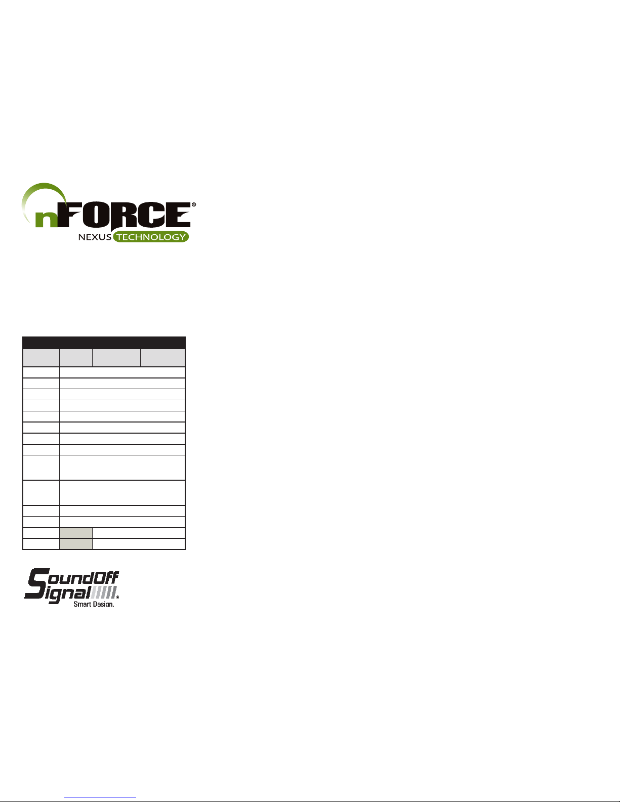
FLASH PATTERNS
PATTERN #
SINGLE
COLOR
DUAL COLOR TRI-COLOR
1 QUINT
2 WARP
3 INTER-CYCLE
4 DOUBLE
5 QUAD
6 POWER PULSE
7 ROAD RUNNER
8 Q-SWITCH
9
STEADY-BURN / ROADRUNNER
(SEQUENCE TYPE 1: STEADY BURN, SEQUENCE
TYPE 2: ROADRUNNER)
10
STEADY-BURN DRIVER TITLE 13 QUAD
(SEQUENCE TYPE 1: STEADY BURN, SEQUENCE
TYPE 2: TITLE 13 QUAD)
11 QUAD 2
12 DOUBLE 2
13 RANDOM 1
14 RANDOM 2
OVER-VOLTAGE PROTECTION
When an over-voltage condition is detected, the module will flash an over-voltage warning pattern of 50mS ON/950mS OFF to alert of the over-voltage condition and protect the electronics from damage due to heat/voltage.
THERMAL COMPENSATION PROTECTION
The LED module is designed to provide maximum power output while providing protection to the electronic components by reducing the output power at extreme temperatures.
SYNC 2
Syncronizing the flashing of multiple light modules is accomplished by connecting the Green and/or Blue wires of different light modules together. Up to 24 light modules can be connected for syncronized flashing. All light module flash patterns
must be set to the same flash pattern # to ensure proper operation. Refer to the Sequence Type section (in Set-Up Table) to setup light modules to flash in alternate or simultaneous flash pattern. NOTE: Will NOT work with non-Sync 2 products such as Ghost, LED3, and Single Color Intersector.
Page 3

1.800.338.7337 / www.soundoffsignal.com
3
ENFSLXSS 11.14
FUNCTION TABLE 1
WIRE LIGHT
RED (SGL)
ORANGE (DUAL)
R/W (SGL)
O/W (DUAL)
WHT (SGL)
YELLOW (DUAL)
SINGLE DUAL TRI
+12V FLASH FLASH DUAL FLASH TRI
+12 CRUISE STEADY CLR 2 STEADY CLR 3
+12V +12V FLASH STEADY CLR 2 STEADY CLR 3
+12V NO OP NO OP NO OP
+12V +12V LOW PWR FLASH FLASH CLR 1 FLASH CLR 1
+12V +12V CRUISE FLASH CLR 2
FLASH CLR 2
+12V +12V +12V LOW PWR FLASH FLASH CLR 1 & 2
FLASH CLR 3
FUNCTION TABLE 2
WIRE LIGHT
RED (SGL)
ORANGE (DUAL)
R/W (SGL)
O/W (DUAL)
WHT (SGL)
YELLOW (DUAL)
SINGLE DUAL TRI
+12V FLASH FLASH CLR 1 FLASH CLR 1 & 2
+12V +12V CRUISE FLASH CLR 1 & 2 FLASH CLR 1, 2 & 3
+12V STEADY CLR 1 STEADY CLR 2 STEADY CLR 3
+12V +12V STEADY CLR 1 STEADY CLR 2 STEADY CLR 3
+12V +12V +12V STEADY CLR 1 STEADY CLR 2 STEADY CLR 3
+12V NO OP NO OP NO OP
FUNCTION TABLE 3
WIRE LIGHT
RED (SGL)
ORANGE (DUAL)
R/W (SGL)
O/W (DUAL)
WHT (SGL)
YELLOW (DUAL)
SINGLE DUAL TRI
+12V FLASH FLASH DUAL FLASH CLR 1, 2 & 3
+12V FLASH LOW PWR
FLASH CLR 1 & 2
LOW PWR
FLASH CLR 1, 2 & 3
LOW PWR
+12V +12V FLASH LOW PWR
FLASH COLOR 1 & 2
LOW PWR
FLASH CLR 1, 2 & 3
LOW PWR
+12V NO OP NO OP NO OP
+12V +12V FLASH LOW PWR
FLASH COLOR 1 & 2
LOW PWR
FLASH CLR 1, 2 & 3
LOW PWR
+12V +12V FLASH LOW PWR
FLASH COLOR 1 & 2
LOW PWR
FLASH CLR 1, 2 & 3
LOW PWR
+12V +12V +12V FLASH LOW PWR
FLASH COLOR 1 & 2
LOW PWR
FLASH CLR 1, 2 & 3
LOW PWR
FUNCTION TABLES
Changing the function table is only enabled when the LED module is in a flashing mode (disabled in cruise or steady ON functions). The functional operation of the LED module can be changed while applying the +V to the Red or Orange wire
with the black wire connected to ground. When the light is flashing, momentarily connect the White or Yellow wire to ground for >4S and <5S (light will go steady high, steady low, off, steady high, steady low) then release. The function
table will now advance to the next table (table 1 to table 2, table 2 to table 3, or table 3 to table 1). Repeat above process until required function table is active.
Page 4

1.800.338.7337 / www.soundoffsignal.com
4
ENFSLXSS 11.14
COLOR SWAP
This function is only valid for dual and tri-color light modules and can only be changed when the light module is in a flashing mode (disabled for single color modules and when light module is operating in cruise or steady ON functions). When
the light is flashing, momentarily connect the white or yellow wire to ground for >2S and <3S (light will go steady high, steady low, off) then release. The light module will switch between Color Swap OFF and Color Swap ON. When Color
Swap is OFF, the 1st color will flash 1st on a dual/tri color pattern. When Color Swap is ON, the 2nd color will flash 1st on a dual/tri color pattern.
SIMULTANEOUS/ALTERNATE
This function can only be changed when the LED module is in a flashing mode (disabled in cruise or steady ON functions) and only has an effect when at least 2 LED modules have the green sync wire connected together. When the light is
flashing, momentarily connect the white or yellow wire to ground for >3S and <4S (light will go steady high, steady low, off, steady high) then release. The light module will switch between Simultanous and Alternate each time this sequence
is done. To have light modules flash simultaneously, both light modules need to be set to the same sequence type (Set-Up Table). To have light modules flash alternately, the light modules need to be set to different sequence types (Set-Up
Table).
ADVANCE PATTERN
Flash pattern can only be changed when the LED module is in a flashing mode (disabled in cruise or steady ON functions). When the light is flashing, momentarily connect the white or yellow wire to ground for >250mS and <1S (light will go
steady high) then release. The flash pattern will advance to the next pattern. If the light module was at the last pattern, the pattern will reset to the 1st pattern.
BACKUP PATTERN
This function is only valid when the LED module is in a flashing mode (disabled in cruise or steady ON functions). When the light is flashing, momentarily connect the white or yellow wire to ground for >1S and < 2S (light will go steady high,
steady low) then release. The flash pattern will backup to the previous pattern. If the light module was at the first pattern, the pattern will change to the last pattern on the list.
PATTERN RESET
This function is only valid when the LED module is in a flashing mode (disabled in cruise or steady ON functions). When the light is flashing, momentarily connect the white or yellow wire to ground for >5S and <6S (light will go steady high,
steady low, off, steady high, steady low, off) then release. The flash pattern will reset to the 1st pattern in the list.
FACTORY RESET
This function is only valid when the LED module is in a flashing mode (disabled in cruise or steady ON functions). When the light is flashing, momentarily connect the white or yellow wire to ground for >6S and <7S (light will go steady high,
steady low, off, steady high, steady low, off, steady high) then release. The LED module will reset to: pattern=1, Function Table=1, Color Swap=OFF, Simultaneous.
SETUP TABLE
SECONDS USER INTERFACE
FROM TO VISUAL FEEDBACK ACTION TAKEN
0 1 STEADY-HIGH (60%) FORWARD ONE PATTERN
1 2 STEADY-LOW (30%) BACKWARD ONE PATTERN
2 3 OFF COLOR SWAP (OFF OR ON )
3 4 STEADY - HIGH (60%)
SEQUENCE TYPE:
SIMULTANEOUS OR ALTERNATE
4 5 STEADY - LOW (30%) SEE FUNCTION TABLE
5 6 OFF
RESET TO PATTERN 1
6 7 STEADY-HIGH (60%)
FACTORY RESET (PATTERN 1, COLOR SWAP:
OFF, SIMULTANEOUS)
SEPARATE COLOR CONTROL: OFF
If held longer than 7 seconds, the light will go back to flashing the current
pattern and no action will be taken.
Page 5

1.800.338.7337 / www.soundoffsignal.com
5
ENFSLXSS 11.14
DOUBLE SURFACE MOUNT TEMPLATE
4.91"
1.30"
2.46"
PILOT HOLE
LOCATION
4X
Ø 0.625
HOLE
2X
PILOT HOLE
LOCATION
2X
2.46”
4.91”
0.625
HOLE
SINGLE SURFACE MOUNT TEMPLATE
Important Printer Note
From the print screen, click on “Actual Size”
in order for the template to print to it’s proper
dimensional size. Verify dimensions are
correct before using template to drill any
permanent holes.
Page 6

1.800.338.7337 / www.soundoffsignal.com
6
ENFSLXSS 11.14
REMOTE MODE: FOR USE WITH bluePRINT SYSTEM ONLY
Connecting the Green or Blue wire to ground before applying power to the Orange, Orange/White, Red or Red/White wires will place the LED module into remote mode and the light output color will be directly controlled by the input wires as
shown below.
For Cruise mode or Low Power control of the LED module, the signal to the control wires must be 100 +/- 2Hz using the duty cycle inputs listed below to produce the light output.
Cruise Mode Duty Cycle
(@ 100Hz)
Input Light Output
40% OFF
50% 5%
60% 10%
Low Power Flash D.C.
(@ 100Hz)
Input Light Output
70% 30%
80% 40%
90%
50%
nFORCE Secondary LED Light Remote Mode Functionality
Red or
Orange
Wire
Red/Wht
or Orange/
Wht Wire
Single Color Dual Color Tri Color
Color
Swap=OFF
Color
Swap=ON
Color
Swap=OFF
Color
Swap=ON
Color
Swap=OFF
Color
Swap=ON
Cruise - Cruise Color 1 Cruise Color 1 Cruise Color 2 Cruise Color 1 Cruise Color 2
- Cruise Cruise Color 2 Cruise Color 1 Cruise Color 2 Cruise Color 1
Cruise Cruise Cruise Color 2 Cruise Color 1 Cruise Color 3 Cruise Color 3
Flash - Flash Color 1 Flash Color 1 Flash Color 2 Flash Color 1 Flash Color 2
- Flash Flash Color 2 Flash Color 1 Flash Color 2 Flash Color 1
Flash Flash Flash Color 2 Flash Color 1 Flash Color 3 Flash Color 3
Steady ON - Steady ON Color 1 Steady ON Color 1
Steady ON Color 2 Steady ON Color 1 Steady ON Color 2
- Steady ON Steady ON Color 2
Steady ON Color 1 Steady ON Color 2 Steady ON Color 1
Steady ON Steady ON Steady ON Color 2
Steady ON Color 1 Steady ON Color 3 Steady ON Color 3
Cruise Flash
Flash Color 2/Cruise
Color 1 during OFF
cycle of Flash
Flash Color 1/Cruise
Color 2 during OFF
cycle of Flash
Cruise Steady ON Steady ON Color 2
Steady ON Color 1
Flash Steady ON Steady ON Color 2
Steady ON Color 1
 Loading...