

Page 1
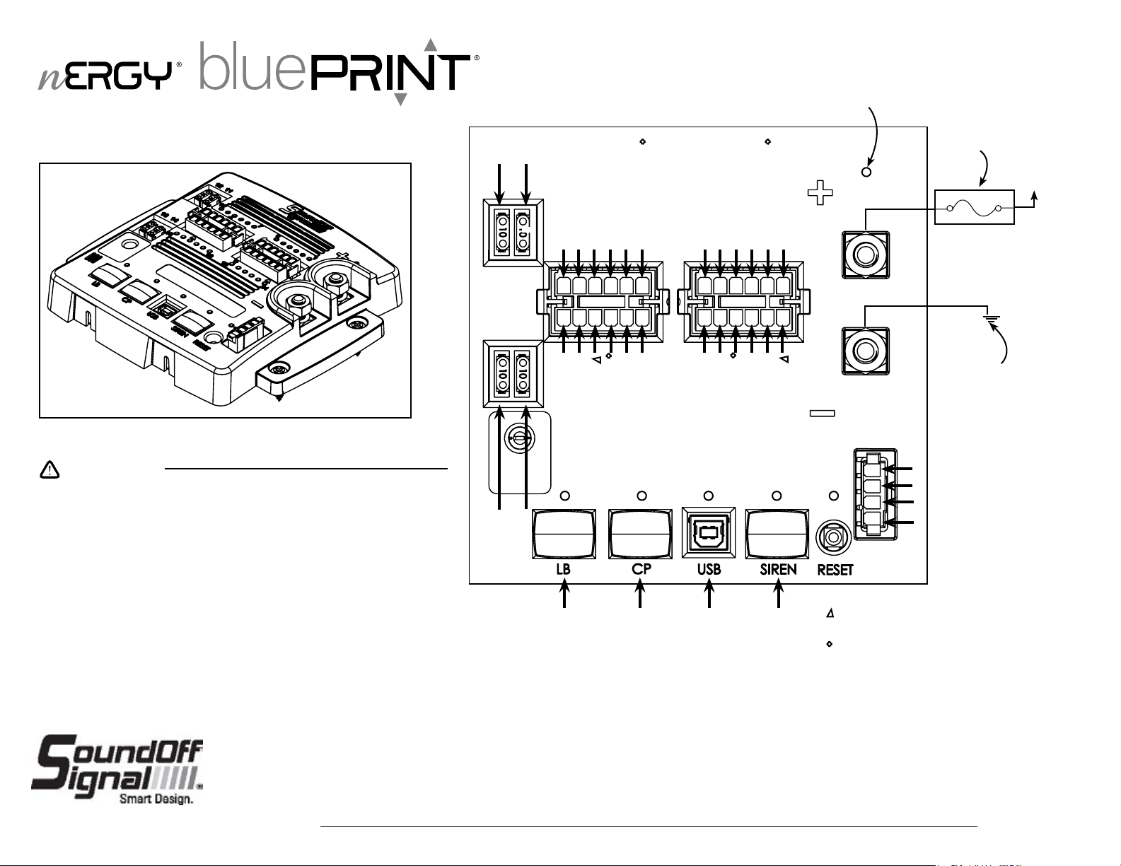
CENTRAL CONTROLLER
PART NUMBER: ENGCC01241
WARNING
•HIGH CURRENT interconnects must be properly terminated. Poor crimp quality can
cause heat build-up and re. Follow crimp connector manufacturer instructions.
•DO NOT install this product or route any wires in the Air Bag Deployment Zone. Refer
to vehicle Owner’s Manual for deployment zones.
•Do NOT use system to disconnect headlights, brake lights or other safety equipment.
•Unit may become hot to touch during normal operation.
•Failure to properly install connectors, fuses or wiring may cause vehicle failure or re.
•Installation must only be performed by trained technician. Installer must determine
vehicle wiring conguration and proper integration of system.
•Use proper wire gauge. All power wires connecting to positive (+) or negative (-)
battery terminal or local chassis ground (-) must be sized to supply at least 125% of
max. current and properly fused at power source.
•Install protective grommets when routing wire through rewall or metal.
Output #12 (Fuse)
2
Output #13 (Fuse)
POWER DIAGNOSTIC LED
AUTOMOTIVE 100A
FUSE OR BREAKER
Output #11 (Fuse)
V
BATT
2
Output #12 (10 Amps)*
Output #11 (10 Amps)*
Output #10 (5 Amps)
Output #9 (10 Amps)
Output #8 (5 Amps)
Output #7 (10 Amps)
Output #6 (5 Amps)
Output #5 (5 Amps)
Output #4 (10 Amps)
Output #3 (5 Amps)
Output #2 (10 Amps)
Output #1 (5 Amps)
+(Power)
-(Ground)
DIRECT BATT GROUND
CONNECTION
Output #13 (10 Amps)*
Output #14 (10 Amps)*
Output #15 (5 Amps)
Output #16 (10 Amps)
Output #17 (5 Amps)
Output #14 (Fuse)
Exterior Lightbar
Output #18 (10 Amps)
Control
Panel
Output #19 (5 Amps)
Output #20 (5Amps)
Output #21 (10 Amps)
Output #22 (5 Amps)
Output #23 (10 Amps)
Output #24 (5 Amps)
USB
Future Use
Ignition
Input Node, 200R, up to 5 Remotes
External Reset
* Constant Power Outputs
Internal Series Diode (to prevent backfeed
from external connections)
Higher inrush current thresholdxenon
1.800.338.7337 / www.soundoffsignal.com
1
Installers and users must comply with all applicable federal, state and local laws regarding use and installation of warning devices.
NOTICE:
Improper use or installation may void warranty coverage. To review our Limited Warranty Statement & Return Policy for this or any SoundOff Signal product, visit our website at
www.soundoffsignal.com/sales-support. If you have questions regarding this product, contact Technical Services, Monday - Friday, 8 a.m. to 5 p.m. at 1.800338.7337 (press #4 to skip the
automated message). Questions or comments that do not require immediate attention may be emailed to techservices@soundoffsigal.com.
SUPERIOR CUSTOMER RELATIONSHIPS. SMARTLY DESIGNED LIGHTING & ELECTRONIC SOLUTIONS.
EVCS_Central Controller_ENGCC01241 5.16
Page 2
CENTRAL CONTROLLER
PART NUMBER: ENGCC01241
WARNING
•Install fuse or breaker (100Amps max.) on main power supply.
•Do NOT connect product to strobe power supply. Product is self-contained; no external power supply
needed.
•Follow attached Wiring and Interconnect requirements.
•Torque the provided M8 nuts with lock washer to a maximum of 7ft-lbs.
-Verify that the lockwasher is fully seated when assembled-
The Central Controller processor stores and interprets the input and output conguration from the software
application and control outputs accordingly as well as monitors outputs for fault conditions. The Central Controller is
fully software congurable via PC Software app through USB connection.
The central controller is the communication hub for other system components within the EV Control System allowing
for:
•A communication port for lightbar
•A communication port for 14 button control panel
•A communication port for other control system devices
•Up to 5 remote nodes
•Input node
•Up to 2 200R siren ampliers
The central controller allows for 24 outputs for connection
to vehicle devices (100 Amps max) and has:
•(4) 10-amp fused outputs - constant power [outputs 11-14]
•(8) 10-amp solid state switchable outputs
•(12) 5-amp solid state switchable outputs
Multi-color lights should be driven by outputs within the same output group (Group 1: 1-5, Group 2: 6-10, Group 3:
15-19, Group 4:20-24) to align timing.
DIAGNOSTIC LED
•Power LED is steady on when the device is powered up and running with no errors.
•Power LED is off when the device is off or in sleep mode.
•Power LED winks when there is a system fault.
•Fault condition is read by counting the number of times the LED “winks”on.
Each fault condition will generate a pattern where each wink is 250ms off/250ms on.
The pattern is terminated by the LED being off for 2.5 seconds.
*The LED will wink multiple patterns when more than one fault condition is active.
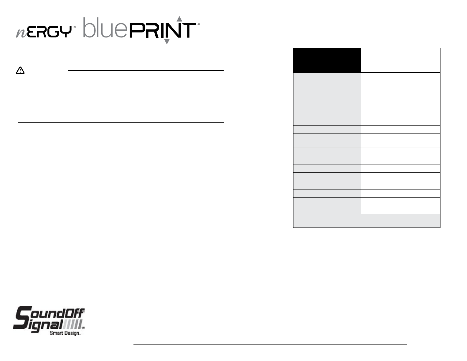
nERGY Control System
Tech Specs
Input Voltage: 10-16Vdc (Negative Ground)
Maximum Load Current: 100 Amps
Outputs (Sum of ALL used Out-
puts Shall Not Exceed 100Amps)
IGN ON: Standby Current: 140mA
IGN OFF: Sleep Current: 0.34mA
Inputs: 1x Ignition Input Active High
Reverse Polarity Protection:
Transient Protection: Protected
High Voltage Protection: >16V; High Voltage Error Code Set
Low Voltage Protection: <9V; Low Voltage Error Code Set
Operating Temp: -40˚C to + 65˚C
Dimensions: 7” x 6.25” x 1”
Weight, Boxed: 1 lb. 7 oz.
Weight, Device Only: 14.9 oz.
Valid Integration Threshold - High >8.5V
The Central Controller is not waterproof. Install in a protected location
away from excessive heat and moisture.
Fault Condition Wink Patterns:
1 Wink - CPDU output(s) are faulted
2 Winks - Communication Fault
3 Winks - Source voltage level is < 9 VDC
4 Winks - Source voltage level is > 16VDC
5 Winks - Over temperature condition
6 Winks - RPDU output(s) are faulted
See attached Install Template to aid in connections and programming
Central Controller
4x 10Amp Fused Battery
8x 10Amp Solid State, Switched
12x 5Amp Solid State, Switched
Not Protected (Reverse Polarity will
Destroy the Devices)
1.800.338.7337 / www.soundoffsignal.com
2
Installers and users must comply with all applicable federal, state and local laws regarding use and installation of warning devices.
NOTICE:
Improper use or installation may void warranty coverage. To review our Limited Warranty Statement & Return Policy for this or any SoundOff Signal product, visit our website at
www.soundoffsignal.com/sales-support. If you have questions regarding this product, contact Technical Services, Monday - Friday, 8 a.m. to 5 p.m. at 1.800338.7337 (press #4 to skip the
automated message). Questions or comments that do not require immediate attention may be emailed to techservices@soundoffsigal.com.
SUPERIOR CUSTOMER RELATIONSHIPS. SMARTLY DESIGNED LIGHTING & ELECTRONIC SOLUTIONS.
EVCS_Central Controller_ENGCC01241 5.16
Page 3

Wiring and Interconnect Requirements for ENGCC01241 Central Controller
WARNING
•High current interconnects require careful termination with the proper equipment. WARNING! Poor crimp quality can cause signicant heat build-up possible safety concerns. Connector
manufacturers provide instructions on how to terminate properly in order to have a safe and reliable connection.
•Central Controller can switch up to a total maximum of 100Amps. User must congure outputs to not exceed this total current. Individual output switches are rated up to 10Amps each for
higher current loads, but the total device current must not exceed 100Amps including the (4) constant on outputs. The software warns when these limits are exceeded and user must
ensure that individual output limits and total device current limits are not exceeded in normal use.
•Do not gang or parallel multiple outputs to drive a high current load. Multiple 5Amp and 10Amp outputs must not be combined to achieve a higher current limit.
TERMINATION OPTION 1
Purchase accessory mating harness from SoundOff Signal
SoundOff P/N: ENGHNK01 – two 12pin Mating Harnesses and one 4pin
Mating Harness
Pros: •No need to terminate at the connector pins
Cons: •Requires butt-splice or alternate connector
0.156” to 0.187”
Strip to this length
Insulation
Crimp
TERMINATION OPTION 2
Purchase individual connector components to terminate the wires at the connector.
TE (AMP) P/N: 1-480287-0 TE (AMP) P/N: 1-480424-0 TE (AMP) P/N: 350557-4
16pin Commercial MATE-N-LOK
Receptacle
•Application Specication 114-1012: http://www.te.com/commerce/DocumentDelivery/DDEController?Action=showdoc&DocId=Spec
ication+Or+Standard%7F114-1012%7FE%7Fpdf%7FEnglish%7FENG_SS_114-1012_E.pdf%7F350557-4
•PRO-CRIMPER III FRAME 354940-1: http://www.te.com/catalog/pn/en/354940-1?RQPN=354940-1
•DIE ASSY: 90575-2: http://www.te.com/catalog/pn/en/90575-2?RQPN=90575-2
•Actual terminal and housing needs may be different depending on application, wire type, etc.
•Extraction tool 1-305183-2: http://www.te.com/catalog/pn/en/1-305183-2?RQPN=1-305183-2
Pros: •Consistent wire colors, clean install without butt-splices
Cons: •Need to purchase crimper and train personnel
4pin Commercial MATE-N-LOK Receptacle
Commercial MATE-N-LOK Socket Terminal
(16-18 AWG wire, used with both receptacles)
(drawn to scale)
1.800.338.7337 / www.soundoffsignal.com
3
Installers and users must comply with all applicable federal, state and local laws regarding use and installation of warning devices.
NOTICE:
Improper use or installation may void warranty coverage. To review our Limited Warranty Statement & Return Policy for this or any SoundOff Signal product, visit our website at
www.soundoffsignal.com/sales-support. If you have questions regarding this product, contact Technical Services, Monday - Friday, 8 a.m. to 5 p.m. at 1.800338.7337 (press #4 to skip the
automated message). Questions or comments that do not require immediate attention may be emailed to techservices@soundoffsigal.com.
SUPERIOR CUSTOMER RELATIONSHIPS. SMARTLY DESIGNED LIGHTING & ELECTRONIC SOLUTIONS.
EVCS_Central Controller_ENGCC01241 5.16
Page 4

CENTRAL CONTROLLER
INSTALL TEMPLATE
AUTOMOTIVE 100
AMP MAX FUSE
OR BREAKER
Department: _________________________________
Vehicle: ______________________________________
Installer / Date: ________________________________
Moun
ng Loca on: _____________________________
NOT USED_____________________________________
Ignition_____________________________________
Remotes/200R/Input Data____________________
External Reset__________________________
ON
Wire Color Fun on
_________________________ 5A, Output 1, Pin 11
_________________________ 10A, Output 2, Pin 9
__________________________ 5A, Output 3, Pin 7
_________________________ 10A, Output 4, Pin 5
__________________________ 5A, Output 5, Pin 3
__________________________ 5A, Output6, Pin 1
________________________ 10A, Output 7, Pin 11
__________________________ 5A, Output 8, Pin 9
_________________________ 10A, Output 9, Pin 7
_________________________ 5A, Output 10, Pin 5
________________________ 10A, Output 11, Pin 3
________________________ 10A, Output 12, Pin 1
Always On, Output 11, 10A
Always On, Output 12, 10A
ON
ON
Function
Pin 12, Output 24, 5A _______________________
Pin 10, Output 23, 10A _______________________
Pin 8, Output 22, 5A _________________________
Pin 6, Output 21, 10A ________________________
Pin 4, Output 20, 5A _________________________
Pin 2, Output 19, 5A _________________________
Pin 12, Output 18, 10A _______________________
Pin 10, Output 17, 5A ________________________
Pin 8, Output 16, 10A ________________________
Pin 6, Output 15, 5A _________________________
ON
Pin 4, Output 14, 10A
ON
Pin 2, Output 13, 10A ________________________
_________________
Always On, Output 14, 10A
Always On, Output 13, 10A
Wire Color
Wire Color
Serial:
Future Use
USB for
gu on &
con
diagno
Serial:
Control Panel
Serial:
Lightbar
only
1.800.338.7337 / www.soundoffsignal.com
4
= Backfeed Protection
= Xenon Inrush
EVCS_Central Controller 5.16
 Loading...