

Page 1
WARNING: Warning devices are strictly
regulated and governed by Federal, State
and Municipal ordinances. These devices
shall be used ONLY on approved vehicles.
It is the sole responsibility of the user of
these devices to ensure compliance.
TECHNICAL SPECIFICATIONS
Overall Dimensions:
Flash Patterns:
Input Voltage:
Current Consumption:
Light Sync Technology:
Operating Temperature:
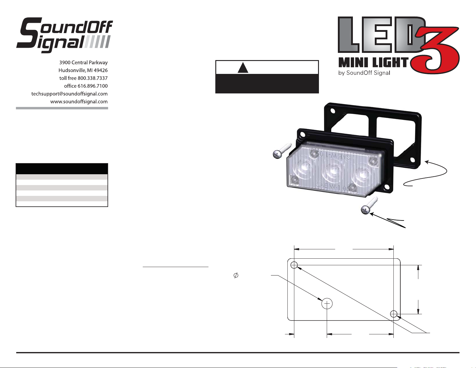
MOUNTING
Important: DO NOT over tighten
mounting screws or nuts. This could
cause permanent damage to the light.
1. Locate flat mounting location for the
LED3 Light.
2. When the position of LED3 is
determined use paper template on
next page to drill hole locations. Screw
mounting holes should be drilled using
a 3/32” drill bit. Wire entry holes
should be drilled using a 1/4” drill bit.
3. Make electrical connections.
4. Using supplied #6 x 3/4” screws, fasten
LED3 to mounting surface. Be sure
not to overtighten screws as this will
cause hole in mounting surface to strip
out. Be sure that supplied gasket is
mounted between mounting surface
and LED3.
2.5"W x 1.375"H x 1.25"D
33
10-16Vdc
0.5 Amps
Yes
-40º to +65º C
SINGLE EXTERIOR
LED3 WARNING LIGHT
ASSEMBLY INSTRUCTIONS
This product contains high intensity LED
devices. To prevent eye damage, DO NOT
stare into light beam at close range.
NOTE: The LED3 is a factory sealed unit that
CANNOT be serviced in the field. Any attempt
to gain access to the LED3 unit will most likely
cause permanent damage and void its
warranty.
IMPORTANT: DO NOT connect this device
to a strobe power supply.
OPERATING INSTRUCTIONS
See Configuration Instructions.
The single LED3 comes equipped with an
internal flasher with 33 user selectable
patterns that can be synchronized either
alternating or simultaneous with up to three
other lights. It can also be put into slave mode
and driven through an external flasher.
1. Connect the LED3 BLACK wire to a good,
convenient ground.
2. Connect the LED3 RED wire to one side of a
user supplied on/off switch. Connect the other
side of the switch, through a 5Amp fuse, to a
source of +10-16Vdc.
EL3SN(x)
!
WARNING
Drill Template for Mounting
Holes/Cord Entry
Template Shown Actual Size
1/4” DRILL
2.21
Supplied Gasket
2x Supplied
#6 x 3/4” Sheet metal Screws
1.085
1.480.73
2xØ3/32”
EL3SN(x) 4.10
Page 2
SINGLE EXTERIOR
LED3 WARNING LIGHT
ASSEMBLY INSTRUCTIONS
PATTERN SELECTION
1. Disconnect WHITE wire from any
connections if applicable.
LED3 Sync Configuration Instructions
IMPORTANT! A MAXIMUM OF 4 SINGLE LIGHTS
CAN BE SYNCED TOGETHER
1. Set ID#
a. Identify which pattern and sequence you want and look up ID# settings below.
b. Connections
i. RED: +12Vdc
ii. WHT: +12Vdc (Note: you will need to disconnect after power is applied)
iii. BLK: Ground
c. Apply power to unit
d. Without disconnecting power from unit, disconnect WHT wire
e. Momentarily connect WHT to Ground to change ID #
i. Identify ID# by number of sequential flashes
ii. Possible ID#s: 1 – 4
f. Disconnect power from unit to get out of ID mode.
2. Set Pattern
a. Reapply power to units.
b. Once all Light Head ID#s are configured, make sure all lights are flashing the
same pattern
c. Connect corresponding colored wires of all units together: RED to RED, etc.
d. Change Pattern
i. Momentarily connect WHT wires to Ground
ii. Observe pattern change on all lights connected
e. Insulate all wires by taping with electrical tape
3. Connect Master Switch for Application
a. IMPORTANT! Ensure WHT Pattern/Sync Wires are tied together
1 LIGHT
Single Light Operation: Follow the ID Selection steps and set the LED3 to ID#1
if it is not already. NOTE: Steady Burn is produced for patterns 9 & 10 in Single
Operation.
2 LIGHTS
ALTERNATING: To obtain Alternating patterns, follow the ID SELECTION steps
and set one LED3 to ID#1 and the other to ID#3. Then proceed to the
PATTERN SELECTION steps.
SIMULTANEOUS: To obtain Simultaneous patterns, follow the ID SELECTION steps and set both LED3 lights to
ID#1. Then proceed to PATTERN SELECTION steps.
4 LIGHTS
X-Pattern: To obtain X-patterns, follow the ID SELECTION steps and set one of the four LED3 lights to ID#1, one
to ID#2, one to ID#3, and one to ID#4. Then proceed to PATTERN SELECTION steps. NOTE: Be sure to mount
each LED3 in the correct placement based on ID#.
2. Turn LED3 ON.
3. Momentarily touching and removing the WHITE
wire(s) to ground will advance the LED3 to the next
flash pattern. Touching and removing the White wire
for more than a few seconds will allow you to change
the LED3 to the previous pattern. See flash pattern
table. Continuing to touch and remove the WHITE
wire(s) to ground will allow you to scroll through the
pattern list. After pattern #33 is reached the list will
start over again at pattern #1.
NOTE: The LED3 is equipped with flash pattern
memory. Once you have selected a pattern the LED3
will always activate to that pattern every time the unit
is turned on. Tape up and secure WHITE wire so that
it will not accidentally change your selected pattern.
PATTERN RESET
1. Remove power.
2. Place WHITE (sync) wire to ground.
3. With sync wire grounded, re-power RED wire.
4. Maintain for one second (light will dim).
5. Remove power and ground (pattern 1 set).
X-Pattern Sequence
ID#1 > ID#4 > ID#2 > ID#3
X-Pattern Light Head Placement
ID#4 ID#2
ID#3 ID#1
EL3SN(x)
SLAVE MODE
The LED3 is capable of being activated through the
use of a user supplied flasher by putting it in slave
mode.
1. Permanently connect the LED3 WHITE and BLACK
wire to a good, convenient ground.
2. Connect the LED3 RED wire, through a 5Amp fuse, to
the output of a +10-16Vdc switching flasher.
NOTE: The LED3 is a factory sealed unit that
CANNOT be serviced in the field. Any attempt to gain
access to the LED3 unit will most likely cause
permanent damage and void its warranty.
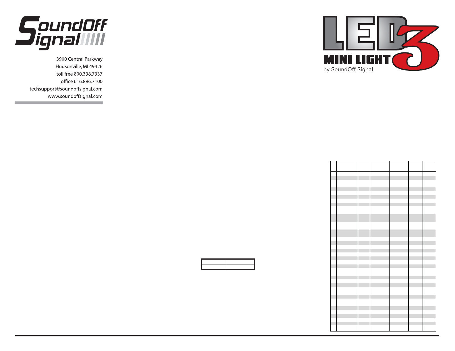
FLASH PATTERNS for
SINGLE HEAD EXTERIOR LED3 (EL3SN(x))
#
Pattern Name 1 Light Alternating
1 Quint X X X 70
2 Warp X X X 350
3 Inter-Cycle X X
Flash
4 Double Flash X X X 70
5 Quad Flash X X X 80
6 Power Pulse X X X 180
7 Road Runner X X X 113
8 Q-Switch X X
9 Road Runner X X 113
Steady Burn
10 Quad X X 80
Steady Burn
11 E-Ideal X X X 200
Single Flash
12 E-Ideal X X X 146
Double Flash
13 Quad2 Flash X X X 67
14 Double2 Flash X X X 95
15 X-Warp X
16 X-Double X
17 PowerRunner X X X
18 LCR Quint X X X
19 Warp³ X X X
20 Ultra Warp X X X 545
21 Thunder and X X
Lightning
22 LiteSpeed X X X 85
23 SuperSonic X X 170
24 LCR LiteSpeed X X X
25 SuperSonic X X X
Ultra
26 TempoShift X X X
27 TempoShift X X X
Warp
28 SBE2 X X X 67
29 C² X X X 200
30 U² X X X 176
31 UltraGlow X X X
32 Cyclone X X X
33 Chameleon X X X
2 Lights
Simultaneous
2 Lights
X-Pattern
Flashes/
4 Lights
EL3SN(x) 4.10
Minute
 Loading...