

Page 1
INTERSECTOR™ LED LIGHT
#ENT3(y)3(x) - SURFACE MOUNT
#PNT3DGBB DECK/ GRILLE BRACKET, BLACK
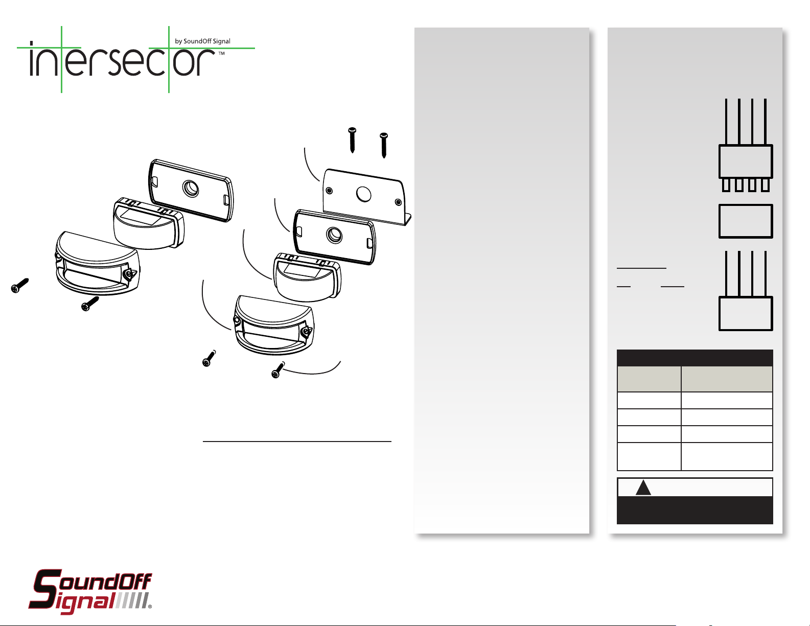
HOUSING
SURFACE MOUNT
BEZEL
GASKET
BRACKET
SURFACE MOUNT
INSTALLATION:
1. Establish a position on the vehicle on a level
surface. Orient the light output level on the
horizon.
2. Use the gasket provided as a template to
mark locations of wire and mounting
screws
3. Use a 5/8” diameter drill for the wire holes
4. Size pilot holes for mounting screws
appropiately.
5. Fasten light using bezel and mounting
screws. Do not torque mounting screws
beyond 20 in - lbs.
DECK/ GRILLE BRACKET
INSTALLATION:
(PURCHASED SEPARATELY)
1. Slide wire from Bezel through center
access hole in the gasket and bracket.
2. Next, position the Housing over the Bezel
and align the holes with the bracket.
OPERATION:
For details on operation see page with ‘Flash
Patterns’ table on last page.
IMPORTANT:
Power should only be
supplied through RED
WIRE of asher harness
and must be fused with
a 3A, user supplied,
in-line fuse. Failure to
install this fuse will create
a re hazard and will
damage the Intersector™
Light. Connecting the
Intersector™ light to any
power source directly
WILL permanently
damage the light and will
void warranty.
IMPORTANT! FOR
PROPER OPERATION
ALL WIRES MUST BE
CONNECTED FROM
FLASHER TO LIGHT
HEAD.
ALL WIRES 22ga
GREEN
BLACK
RED
WHITE
MALE
CONNECTOR
FROM FLASHER
1324
FEMALE
CONNECTOR
1324
RED
BLACK
GREEN
INTERSECTOR
WHITE
LIGHT
8/32 x 1” PHIL PAN SCREWS
DECK/ GRILLE BRACKET MOUNT
Please see last page for
Technical Specifications
Important Information:
• Warning devices are strictly regulated and governed by Federal, State and Municipal ordinances.
These devices shall be used ONLY on approved vehicles. It is the sole responsibility of the user of these
devices to ensure compliance.
• DO NOT install this product or route any wires in the Air Bag Deployment Zone. Refer to your vehicle
Owner’s Manual for the location of any air bag deployment zones.
• DO NOT connect this device to a strobe power supply. This product is self-contained and does not
require an external power supply.
To review our Limited Warranty Statement & Return Policy for this or any SoundOff Signal product please visit our website.
If you have questions regarding this product please contact Technical Services, Monday - Friday, 8 am to 5 pm at 1.800.338.7337, press #4 to skip the automated message.
Questions or comments that do not require immediate attention may be emailed to techsupport@soundoffsignal.com.
1.800.338.7337. / www.soundoffsignal.com / Thank you for trusting us with your safety!
3. Lastly, using the supplied 8-32 x 1”
screws fasten the assembly lightly. Do
not torque mounting screws beyond 20
in - lbs.
4. Establish a position on the vehicle on a level
surface. Orient the light output level on the
horizon.
5. Use the bracket provided as a template to
mark locations of mounting screws.
6. Size pilot holes for mounting screws
appropiately.
7. Fasten light using bezel and mounting
screws. Do not torque mounting screws
beyond 20 in - lbs.
WIRE HOOK-UP TABLE
WIRE COLOR:
(ALL WIRES 20ga)
CONNECT TO:
(FROM FLASHER ONLY)
RED +10-16 Vdc
WHITE Pattern Select / Sync
BLACK Ground (-)
GREEN
WARNING
!
This product contains high intensity LED devices. To
prevent eye damage, DO NOT stare into the light
Intersector™ LED Light ENT3(x)3(x).pdf ~ Rev. 03.12
beam at close range.
Cruise Mode
(+10-16 Vdc)
Pg. 1
Page 2
INTERSECTOR™ LED LIGHT
#ENT3(y)3(x) - SURFACE MOUNT
#PNT3DGBB DECK/ GRILLE BRACKET, BLACK
PATTERN RESET
1. Remove power.
2. Place WHITE (sync) wire to ground.
3. With sync wire grounded, re-power RED wire.
4. Maintain for one second (light will dim).
5. Remove power and ground (pattern 1 set).
Tech Specs Intersector™
Flash Patterns:
Light Sync:
Technology:
Mounting:
Input Voltage:
Current Draw:
Dimensions:
Operating Temp.:
-40° to +65° C / -104° to +149° F
Patents:
Parts & Accessories:
Intersector SM Module PENT3BO
SM Intersector Bezel (Black) PNT3SMBB SM
SM Intersector Bezel (Chrome) PNT3SMBC SM
SM Intersector Bezel (White) PNT3SMBW SM
SM Intersector Gasket PNT3SMGS SM
Deck/ Grille Intersector Brkt (Black) PNT3DGBB
30 Flash Patterns
Yes
9 Gen3 LEDs
Surface Mounts or Deck/ Grille
Bracket Mount
10 - 16 Vdc
less than 1.5 amps
Width x Height x Depth
4” (98 mm) W x 2” (49 mm) H
x 2” (49 mm) D
US Design Patent No. D636,113
*Other Patents Pending*
SINGLE LIGHT HEAD SET UP AND PATTERN SELECTION
1. Disconnect WHITE wire from any connections if applicable.
2. Turn Intersector™ LED LIGHT ON by applying power to RED WIRE
from asher. IMPORTANT NOTE: Power harness with in-line asher
(PNT(x)FLA) MUST be used between power and light. Any other
flasher WILL cause permanent damage and void warranty.
3. Momentarily touching and removing the WHITE wire to ground
will advance the Intersector™ LED LIGHT to the next ash pattern.
Touching and removing the WHITE wire for more than a few seconds
will allow you to change the Intersector™ LED LIGHT to the previous
pattern. See ash pattern table. Continuing to touch and remove the
WHITE wire to ground will allow you to scroll through the pattern list.
After pattern #30 is reached the list will start over again at pattern
#1.
SINGLE COLOR CONFIGURATIONS
Follow the ID selection steps and set the Intersector™ LED LIGHT to
the following ID:
ID #2 - Single Color ID #4 - Single Color
Single Color - Simultaneous Flash Patterns:
- Set light heads to same ID (#2 or #4).
Single Color - Alternating Flash Patterns:
- Set one light head to ID #2 and another to ID #4.
MULTIPLE LIGHT HEAD SET UP AND PATTERN SELECTION
1. Set ID#
a. Connections
i. RED: +10-16Vdc
ii. WHITE: +10-16Vdc (Note: you will need to disconnect after
power is applied)
iii. BLK: Ground
iv. GREEN: NO CONNECTION REQUIRED FOR ID SELECTION
b. Apply power to unit
c. Without disconnecting power from unit, disconnect WHITE wire
d. Momentarily connect WHITE to Ground to change ID #
i. Identify ID# by number of sequential ashes
ii. Possible ID#s: 2 or 4
e. Disconnect Power to exit ID mode
2. Set Pattern - Must be done individually to each light prior to
syncing
a. RED: +10-16Vdc
b. BLACK: Ground
c. While light is powered, tap WHITE wire to ground to advance to
the next pattern (SEE pattern table at right)
d. Disconnect Power
3. Sync Lights
a. Once desired pattern has been selected for all light heads
connect all white wires and insulate with electrical tape.
4. Connect Master Switch for Application.
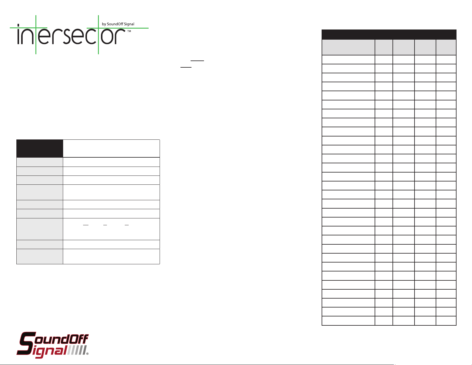
Flash Patterns
Pattern Name 1 Light
1. Quint
2. Warp
3. Inter-Cycle Flash
4. Double Flash
5. Quad Flash
6. PowerPulse™
7. RoadRunner™
8. Q-Switch™
9. RoadRunner™ Steady Burn
10. Quad Steady Burn
11. E-Ideal Single Flash
12. E-Ideal Double Flash
13. Quad2 Flash
14. Double2 Flash
15. PowerRunner
16. LCR Quint
3
17. Warp
18. Ultra Warp
19. Thunder & Lightning
20. Lite Speed
21. SuperSonic
22. LCR Lite Speed
23. SuperSonic Ultra
24. Tempo Shift
25. Tempo Shift Warp
26. SBE2
2
27. C
2
28. U
29. Cyclone2
30. Chameleon2
x x x 70
x x x 350
x x
x x x 70
x x x 80
x x x 180
x x x 113
x x
x x 113
x x 80
x x x 200
x x x 146
x x x 67
x x x 95
x x x
x x x
x x x
x x x 545
x x
x x x 85
x x 170
x x x
x x x
x x x
x x x
x x x 67
x x x 200
x x x 176
x x x
x x x
Alternating
2 Lights
Simultaneous
2 Lights
F.P.M.
(Flashes /
Minute)
Intersector™ LED Light ENT3(x)3(x).pdf ~ Rev. 03.12
Pg. 2
 Loading...