

Page 1
IGNITION SECURITY SYSTEM (I.S.S)
ETISSØ-Ø7+
The ETISSØ-Ø7+ Ignition Security System is designed to allow the vehicle to stay running when the key
is removed from the ignition switch. If the brake is pressed, or if the vehicle is put in reverse, the engine
will stop running.
OPERATION
Activating I.S.S.
1 Start vehicle.
2 Momentarily press switch 1 time for Horn Mode. Light will fl ash to indicate I.S.S. is active and horn
is enabled.
3 Press 2nd time within 2 seconds for No-Horn Mode. Light will be steady ON to indicate I.S.S. is
active but horn is disabled.
4 Low Voltage detection. In the event a low voltage is detected and Horn Mode is activated the horn
will sound every 5 seconds to alert operator the electrical system has a problem.
5 When in horn mode and I.S.S. is tripped the horn output will pulse 12Vdc.
De-activating I.S.S.
1 For security, pressing switch will not de-activate I.S.S.
2 Place key back in ignition and turn to “RUN” position.
3 Press Brake pedal or Shift vehicle into reverse.
a Vehicle will continue to run.
b Light will turn Off.
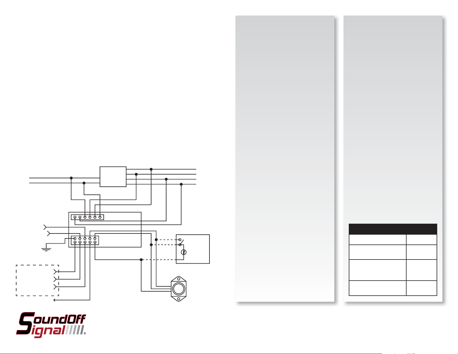
INPUT
BRAKE INPUT
BACKUP INPUT
GROUND
AUXILLARY OUTPUT
COMMON
NORMALLY CLOSED
NORMALLY OPEN
TO HORN RELAY
BLUE
YELLOW
BLACK
WHITE/RED
WHITE/BLACK
WHITE
ORANGE
RED
IGNITION SECURITY SYSTEM
GRAY
IGNITION
SWITCH
YELLOW
GREEN
WHITE
GREEN
GREEN
ORANGE
BLUE
ORANGE
RED
SUPPLIED SWITCH
RED
USER SUPPLIED
OUTPUT
SWITCH
MOMENTARY
SWITCH
LAMP
INSTALLATION:
NOTE:
Before beginning installation, carefully
remove the battery cable from the negative
post of the battery.
NOTE:
White output wire must be used for
ignition security system to operate
correctly.
If using the ETISSØ-Ø7+ with a tail light
fl asher, be sure that it has isolation in the
reverse and brake wire. Without isolation
it will cause the I.S.S. to trip and turn the
vehicle off.
ETISSØ-Ø7+ Ignition Security
System
The ETISSØ-Ø7+ may not operate correctly
if your vehicle has any of the following:
computer interfacing circuits connected to
the brake or reverse switch, factory or after
market anti-theft or alarm systems.
Customer must always verify that their
vehicle can accept the ETISSØ-Ø7+ ignition
security system. Failure to do so may result
in damage to the I.S.S., vehicle wiring or
other components. Failure to follow the
above caution will void any warranty claim
with SoundOff Signal.
Mounting:
It is recommended to mount the module
behind the dash and within the wire length
of the steering column. Be sure that the
module is securely mounted.
Mount the switch box in convenient
location.
CAUTION
DO NOT over tighten the mounting screws
on either the I.S.S. box or the control switch
to prevent damage to the mounting tabs.
ELECTRICAL SPECIFICATIONS
Operating Voltage 10-16Vdc
Inupt Current (Red and
Orange Wires)
Output Current (White,
Yellow, Green and Blue
Wires)
Brake/Reverse Input Trip
Voltage
20A Max
each wire
10A Max
each Wire
10-16Vdc
To review our Limited Warranty Statement & Return Policy for this or any SoundOff Signal product please visit our website at www.soundoffsignal.com and select the “Warranty & Returns”
link along the left column of our home page. If you have questions regarding this product please contact Technical Services, Monday - Friday, 8 am to 5 pm at 1.800.338.7337, press #4 to
skip the automated message. Questions or comments that do not require immediate attention may be emailed to techsupport@soundoffsignal.com.
1.800.338.7337. / www.soundoffsignal.com / Thank you for trusting us with your safety!
ETISSØ-Ø7+ 4.09
 Loading...