

Page 1
INSTALLATION:
OPERATION:
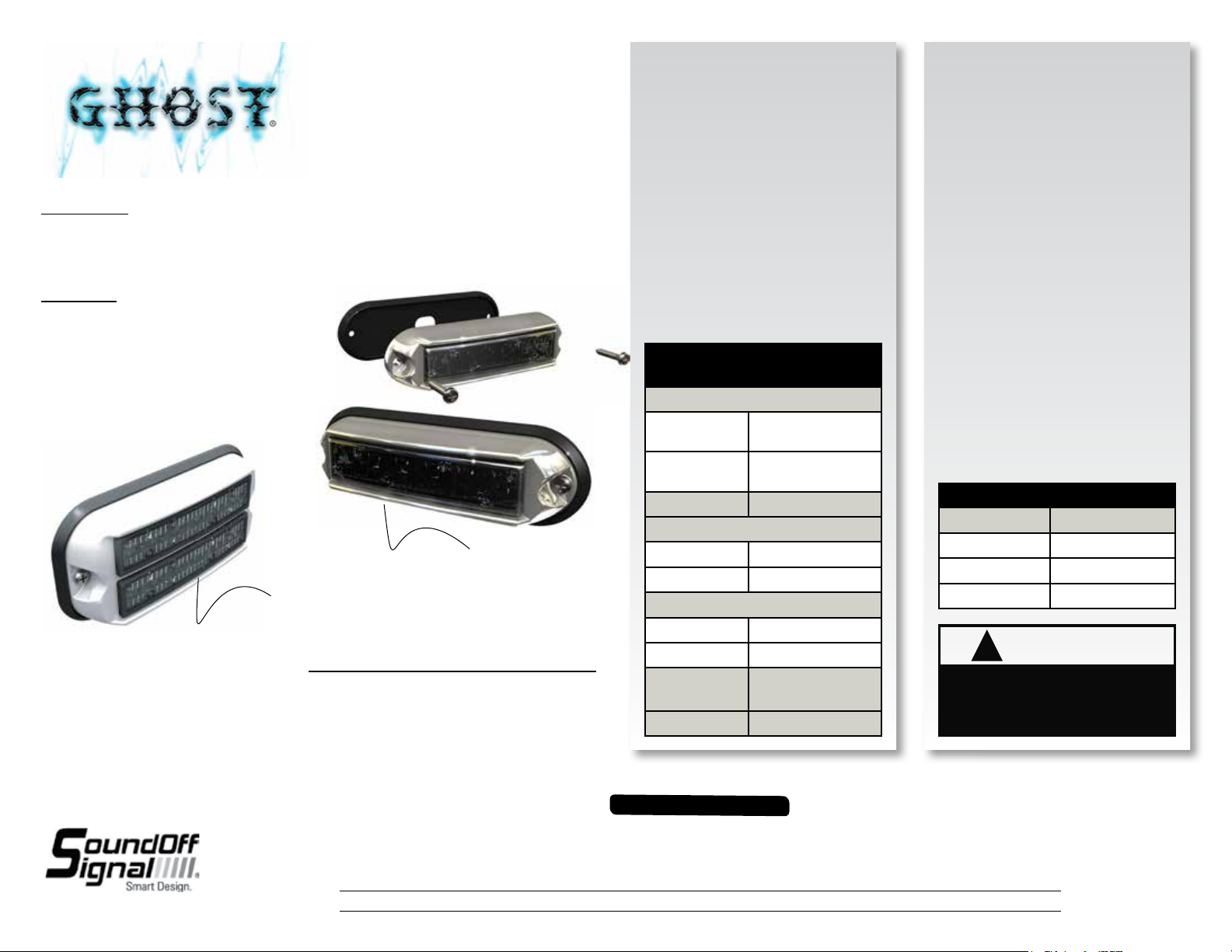
GHOST® SINGLE/DUAL SURFACE MOUNT LIGHT
Single Light:
Black Housing: #EGHST2(x)-12
Chrome Housing: #EGHST2(x)C-12
White Housing: #EGHST2(x)W-12
Dual Light:
Black Housing: #EGHST6(x)B-12
Chrome Housing: #EGHST6(x)C-12
White Housing: #EGHST6(x)W-12
EGHST2(x)C-12
EGHST6(x)W-12
Important Information:
• Warning devices are strictly regulated and governed by Federal, State and Municipal ordinances.
These devices shall be used ONLY on approved vehicles. It is the sole responsibility of the user of these
devices to ensure compliance.
• DO NOT install this product or route any wires in the Air Bag Deployment Zone. Refer to your vehicle
Owner’s Manual for the location of any air bag deployment zones.
• DO NOT connect this device to a strobe power supply. This product is self-contained and does not
require an external power supply.
Warning devices are strictly regulated and governed by Federal, State and Municipal ordinances. These devices shall be used ONLY on approved vehicles. It is the sole responsibility of the user of these devices to ensure compliance.
To review our Limited Warranty Statement & Return Policy for this or any SoundOff Signal product, visit our website at www.soundoffsignal.com/sales-support.
1.800.338.7337 / www.soundoffsignal.com
If you have questions regarding this product, contact Technical Services, Monday - Friday, 8 a.m. to 5 p.m. at 1.800.338.7337 (press #4 to skip the automated message).
SUPERIOR CUSTOMER RELATIONSHIPS. SMARTLY DESIGNED LIGHTING & ELECTRONIC SOLUTIONS.
Questions or comments that do not require immediate attention may be emailed to techservices@soundoffsigal.com.
Establish the mounting position on the
vehicle. Use the gasket (included) as
a template to drill three ؽ” holes for
the light wire and pilot holes for the
mounting screws. Note: pilot holes are
4 7/8” on center.
Caution: Do not stretch the mounting
gasket as this may change the
required hole spacing.
TECHNICAL
SPECIFICATIONS
Overall Dimensions:
Single
Dual
5.65” L x 1.06” H
x 1.8 ” D
5.5” L x 2.5” H
x 1 ” D
Input Voltage: 10 - 16 Vdc
Current Consumption:
Single <1 amp
Dual <2 amps
# of LEDs:
Single 6 Generation 3 LEDs
Dual
12 Generation 3 LEDs
Operating
Temperature:
-40º to +65º C
Flash Patterns: 33
IMPORTANT INFORMATION:
WIRE CONNECTIONS
See setup procedure on second page.
The single GHOST® comes equipped with
an internal flasher with 33 user selectable
patterns that can be synchronized either
alternating or simultaneous with up to three
other lights. It can also be put into slave
mode and driven through an external flasher.
1. Connect the GHOST BLACK wire to a
good, convenient ground.
2. Connect the GHOST RED wire to one side
of a user supplied on/off switch. Connect
the other side of the switch, through a
5Amp fuse, to a source of
+10 - 16 Vdc.
NOTE: The GHOST is a factory sealed unit
that CANNOT be serviced in the field. Any
attempt to gain access to the GHOST unit
will most likely cause permanent damage
and void its warranty.
WIRE HOOK-UP TABLE
WIRE COLOR: CONNECT TO:
RED +10 - 16 Vdc
BLACK Ground (-)
WHITE Pattern Select
!
WARNING
This product contains high
intensity LED devices. To prevent
eye damage, DO NOT stare into
light beam at close range.
EGHST2(xx)-12 07.14
Page 2
GHOST® SINGLE/DUAL SURFACE MOUNT LIGHT
NOTE: GHOST is equipped with Flash Pattern Recall. Once you
have selected a pattern the light will always activate to that pattern every time the unit is turned on. Tape up and secure WHITE
wire so that it will not accidentally change your selected pattern.
LIGHT SYNC CONFIGURATION INSTRUCTIONS
IMPORTANT! A MAXIMUM OF 2 DUAL LIGHTS CAN BE SYNCED.
1. Set ID #:
a. Identify which pattern and sequence you want and look up
ID # settings at left.
b. Connections
i. RED: +10 - 16 Vdc
ii. WHITE: +10 - 16 Vdc
(Note: you will need to disconnect after power is applied)
iii. BLACK: Ground
c. Apply power to unit
d. Without disconnecting power from unit, disconnect
WHITE wire
e. Momentarily connect WHITE to Ground to change ID #
i. Identify ID # by number of sequential flashes
ii. Possible ID #s: 1 – 4
f. Disconnect power from unit to get out of ID mode
2. Set Flash Pattern:
a. Reapply power to units
b. Once all Light Head ID #s are configured, make sure all
lights are flashing the same pattern.
c. Connect corresponding colored wires of all units together:
RED to RED, etc.
d. To Change Flash Pattern:
i. Momentarily connect WHITE wires to Ground
ii. Observe pattern change on all lights connected
e. Insulate all wires by taping with electrical tape
3. Connect Master Switch:
a. IMPORTANT! Ensure WHITE Pattern/Sync Wires are tied
together
SLAVE MODE
GHOST Surface Mount is capable of being activated through the
use of a user supplied flasher by putting it in Slave Mode.
1. Permanently connect the WHITE and BLACK wires to a good,
convenient ground.
2. Connect the RED wire, through a 5 Amp fuse, to the output of a
+10 - 16 Vdc switching flasher.
1.800.338.7337 / www.soundoffsignal.com
1 (one) LIGHT
Follow the Light Sync Configuration Instructions and set the GHOST
light to the following ID:
- Alternating (default): ID #1 or ID #3 (inludes cycle patterns
and steady burn patterns)
- Simultaneous: ID #2 or ID #4 (both lights will flash together
regardless of pattern)
2 (two) LIGHTS
Follow the Light Sync Configuration Instructions and set the GHOST
lights to the following ID:
IMPORTANT: Make sure both lights flash the same pattern!
- Both assemblies simultaneous with individual lights alternating.
- Example: Driver/Passenger sim; Dr.(left alt right)
Pass.(left alt right)
- Set both GHOST Assemblies to ID #1
- Both assys. alternating with individual lights alternating.
- EX: Dr./Pass. alt; Dr.(left. alt. right.) Pass.(right alt. left)
- Set one GHOST to ID #1 and the other to ID #3
- Both assys. alternating with individual lights simultaneous
- EX: Dr./Pass. alt; Dr.(left sim left) Pass.(right sim right)
- Set one GHOST to ID #2 and the other to ID #4
- Both assys. simultaneous with individual lights simultaneous.
- EX: Dr./Dr. sim; Dr.(left sim left) Pass.(right sim right)
- Set both GHOST housings to ID #2
X-PATTERN - To obtain X-Patterns, follow the ID SELECTION steps
and set one of the four GHOST lights to ID #1, one to ID #2, one to
ID #3, and one to ID #4. Then proceed to the PATTERN SELECTION
steps.
NOTE: Be sure to mount each GHOST in the correct placement based
on ID#.
PATTERN SELECTION
1. Disconnect WHITE wire from any connections if applicable.
2. Turn GHOST ON.
3. Momentarily touching and removing the WHITE wire(s) to ground
will advance the GHOST to the next flash pattern. Touching and
removing the White wire for more than a few seconds will allow
you to change the GHOST to the previous pattern. See flash pattern
table. Continuing to touch and remove the WHITE wire(s) to ground
will allow you to scroll through the pattern list. After pattern #33 is
reached the list will start over again at pattern #1.
X-PATTERN SEQUENCE X-PATTERN LIGHT HEAD PLACEMENT
ID#1>ID#4>ID#2>ID#3
PATTERN RESET
1. Remove power
2. Place WHITE (sync) wire to ground
3. With sync wire grounded, re-power RED wire
4. Maintain for one second (light will dim)
5. Remove power and ground (pattern 1 set)
ID#4 ID#2
ID#3 ID#1
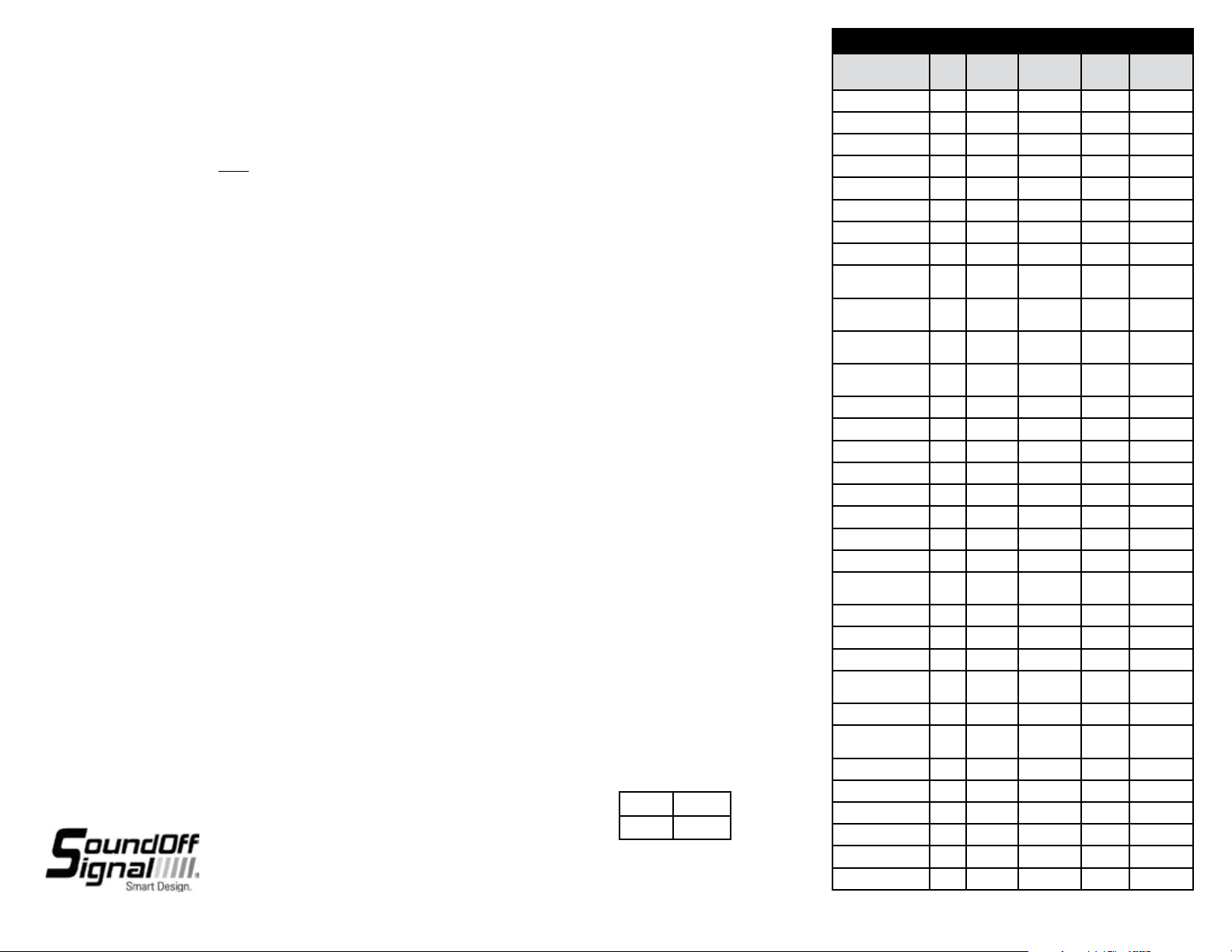
Flash Pattern Name
1. Quint
2. Warp
3. Inter-Cycle Flash
4. Double Flash
5. Quad Flash
6. PowerPulse
7. RoadRunner
8. Q-Switch
9. RoadRunner Steady
Burn
10. Quad Steady Burn
11. E-Ideal Single Flash
12. E-Ideal Double Flash
13. Quad2 Flash
14. Double2 Flash
15. X-Warp
16. X-Double
17. PowerRunner
18. LCR Quint
3
19. Warp
20. Ultra Warp
21. Thunder & Lightning
22. Lite Speed
23. SuperSonic
24. LCR Lite Speed
25. SuperSonic Ultra
26. Tempo Shift
27. Tempo Shift Warp
28. SBE2
2
29. C
2
30. U
31. Ultra Glow
32. Cyclone
33. Chameleon
1 Light
Flash Patterns
2 Lights
Alternating
x x x 70
x x x 350
x x
x x x 70
x x x 80
x x x 180
x x x 113
x x
x x 113
x x 80
x x x 200
x x x 146
x x x 67
x x x 95
x x x
x x x
x x x
x x x 545
x x
x x x 85
x x 170
x x x
x x x
x x x
x x x
x x x 67
x x x 200
x x x 176
x x x
x x x
x x x
2 Lights
Silmultaneous
4 Lights
X-Pattern
x
x
EGHST2(xx)-12 07.14
Flashes per
Minute (FPM)
 Loading...