

Page 1
STROBE POWER SUPPLY
ETN660-P, ETG690-P, ETG6110
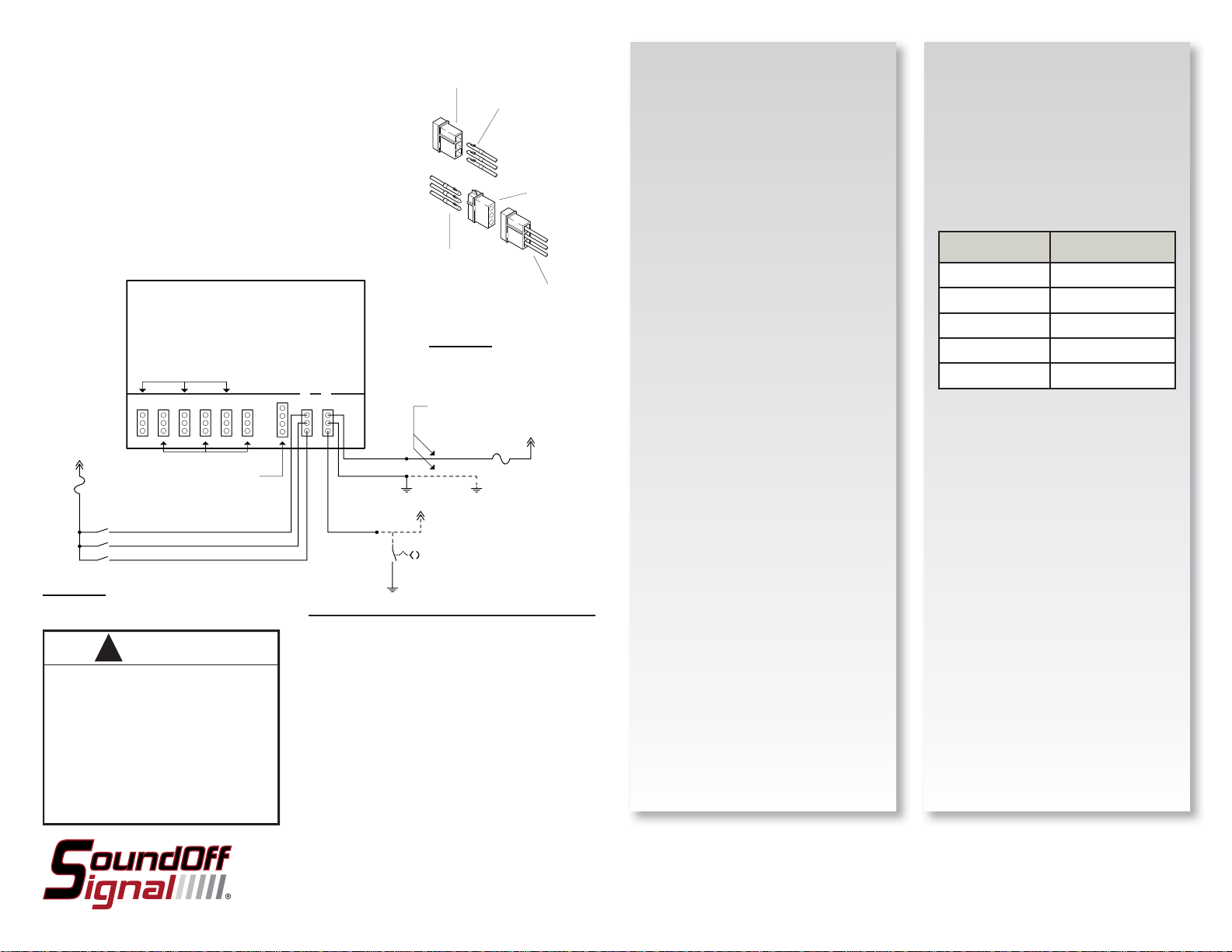
SIMULTANEOUS FLASH A
Output Sockets #:
+10-30Vdc
FH2
FIGURE A
Important Information:
WARNING
PERSONAL INJURY HAZARD
Mounting this device in an improper location
may impair the designed safety
characteristics of the vehicle in the event of a
Consult the vehicle manufacturer before
installing this or any other after market device
to determine its proper mounting location.
Failure to consult and follow the vehicle
manufacturer's mounting recommendations
may result in serious personal injury or death.
123456
SIMULTANEOUS FLASH B
1 Amp
YELLOW-Enable Outputs 5 and 6
GREEN-Enable Outputs 3 and 4
BLUE-Enable Outputs 1 and 2
!
collision.
Diagnostic
Indicator Output
(ETG6110 only)
CONTROL INPUT SOCKET
POWER INPUT SOCKET
RED
BLACK
VIOLET
MALE AMP CONNECTOR
(to be mated with the
AMP output socket on the
Power Supply)
Insert wires with
male pins into the
proper locations in
the male AMP
connector.
RED WIRE - HOLE #1
BLACK WIRE - HOLE #2
WHITE WIRE - HOLE #3
Insert wires with
female pins into
the proper
locations in the
female AMP
connector
AMP WIRE HARNESS
(attached to Strobe
Light Head)
FIGURE B
WIRE EXTENSION
REQUIREMENTS (SEE
POWER INPUT)
+10-30Vdc
Connect to +V to enable
Low Power Mode
Momentary ground to
change pattern
SW1
Please see reverse for
Technical Specifi cations
+10-30Vdc
FH1
15 Amp
FEMALE AMP
CONNECTOR
INSTALLATION:
1. Install power supply in a protected location
using base as the template.
2. Carefully Route the 3 conductor strobe
cable from the lights to the power supply
making sure to prevent cable from chafi ng,
binding, and keep away from engine hot
spots. Also note the male terminals are
toward the power supply and the female
terminals are near the lighthead.
3. Insert the terminals on each end of the
conductor cables into the Tyco connectors
as shown in Figure B. Ensure the correct
color code is followed.
4. Connect the cables to the strobe light heads
5. Connect the cables to the power supply
output sockets (refer to FIGURE A).
6. To Reduce EMI Emissions, ONE end of
the shield (drain) wire of the lighthead
extension cables needs to be connected to
reliable ground. The other end of the sheild
wire needs to be taped or cut.
WARNING!
HIGH VOLTAGE! Please wait 5 minutes after
removing power before attempting service.
No user serviceable parts inside. Warranty
void if seal is broken
This power supply is NOT WATERPROOF
DO NOT attempt to connect non Gaseous
Discharge (ie strobe) lamps into the power
supply as this will cause permanent damage
to the power supply and / or lightheads.
Power Input (See FIGURE A):
1. Plug 3 pin harness (Red, Black, Violet) into
the power input socket on power supply.
2. Connect Black wire to reliable ground.
3. Connect Red wire to properly rated wire
providing +V to the power supply. Use the
chart below as a guideline when selecting
the wire gauge:
LENGTH WIRE GAUGE
1’-10’ 16AWG
11’-20’ 14AWG
21’-30’ 12AWG
31’-40’ 10AWG
>40’ Consult Factory
Control Input (See FIGURE A):
1. Plug 3 pin harness (Blue, Green, Yellow) into
the control input socket on power supply.
2. Connect Blue, Green, and Yellow wires to
switch connected to +V through fuse.
3. Providing +V to blue wire will activate
outputs 1 and 2 in alternating fl ash.
4. Providing +V to Green wire will activate
outputs 3 and 4 in alternating fl ash.
5. Providing +V to Yellow wire will activate
outputs 5 and 6 in alternating fl ash.
Pattern selection
1. Provide +V to the blue, green, and yellow
wires.
2. Momentarily connect the Violet wire to
ground. The pattern will now change
3. Once required pattern has been selected,
either tape the end of the violet wire or
connect to a switch which will provide +V
when the user wants to operate the power
supply in low power mode.
To review our Limited Warranty Statement & Return Policy for this or any SoundOff Signal product please visit our website at www.soundoffsignal.com and select the “Warranty & Returns”
link along the left column of our home page. If you have questions regarding this product please contact Technical Services, Monday - Friday, 8 am to 5 pm at 1.800.338.7337, press #4 to
skip the automated message. Questions or comments that do not require immediate attention may be emailed to techsupport@soundoffsignal.com.
1.800.338.7337. / www.soundoffsignal.com / Thank you for trusting us with your safety!
ET(x)6(xxx) 9.09
Page 2
STROBE POWER SUPPLY
ETN660-P / ETG690-P / ETG6110
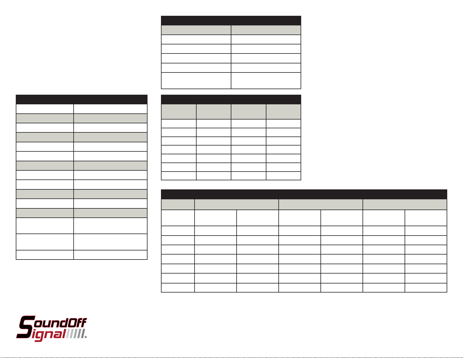
POWER INPUT / CONTROL WIRES
WIRE COLOR: CONNECT TO:
BLUE (+10-30Vdc) Activates Heads 1-2
GREEN (+10-30Vdc) Activates Heads 3-4
YELLOW (+10-30Vdc) Activates Heads 5-6
VIOLET (+10-30Vdc) Activates Low Power Mode
VIOLET (MOMENTARY
Changes Pattern
GROUND)
TECHNICAL SPECIFICATIONS
Overall Dimensions: 6.62”H x 4.82”W x 2.65”D
Flash Patterns: 7 fl ash patterns
Input Voltage Range:
10 - 30 Vdc
Input Current @12Vdc: 6 Amps (ETN660-P)
9 Amps (ETG690-P)
11 Amps (ETG6110)
Output Power: 60 Watts (ETN660-P)
90 Watts (ETG690-P)
110 Watts (
ETG6110)
# of Outputs: 6
Operating Temperature: -40º to +65º C
Contents: 1 ea. Strobe Power Supply
1 ea. 3 pin power input
harness (Red, Black, Violet)
1 ea. 3 pin control input
harness (Blue, Green, Yellow)
1 ea. Installation Instructions
FLASH PATTERNS
PATTERN TIME-
PRIMARY
Quad 170mS 85mS 70
Double 170mS 85mS 115
Quint 85mS 85mS 70
Warp 85mS - 350
Inter-Cycle 85mS 85mS -
Triple 85mS 85mS 90
Single - - 175
TIMESECONDARY
FLASHES /
MINUTE
FLASH ENERGY
ETN660-P ETG690-P ETG6110
PATTERN: JOULES
(PRIMARY)
JOULES
(SECONDARY)
JOULES
(PRIMARY)
JOULES
(SECONDARY)
JOULES
(PRIMARY)
(SECONDARY)
Quad: 10.3 5.1 14 7.6 17 8.4
Double: 10.3 5.1 14 7.6 17 8.4
Quint: 5.1 5.1 7.6 7.6 8.4 8.5?
Warp: 5.1 - 7.6 - 8.4 -
Inter-Cycle 5.1 5.1 7.6 7.6 8.4 8.4
Triple: 10.3 5.1 14 7.6 17 8.4
Single: 10.3 - 14 - 17 -
JOULES
ET(x)6(xxx) 9.09
 Loading...