

Page 1
COMPASS FENDER LIGHT
ECPGHKC1B(xx) - GM CAPRICE
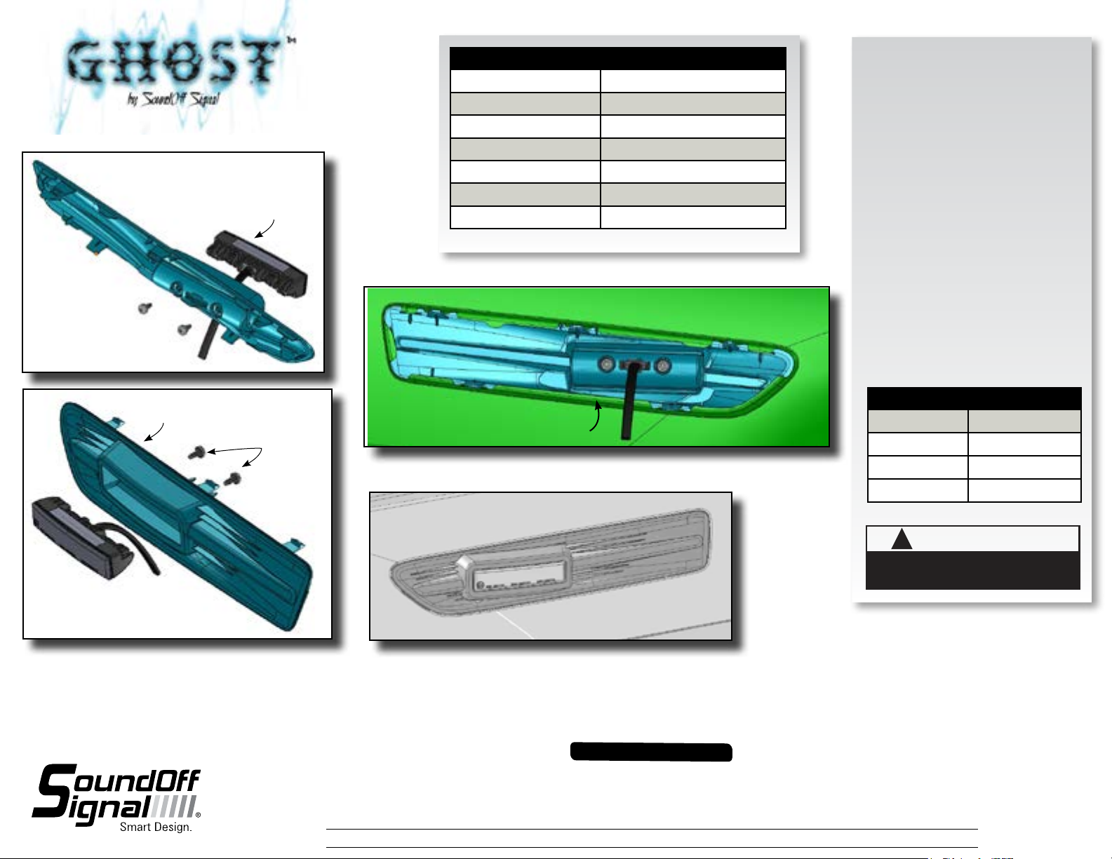
- Fender Light pre-assembly -
Light Assembly
Fig. 1
Ghost
TECHNICAL SPECIFICATIONS
Overall Dimensions: 14”L x 2.75”W x 1.5”D
Flash Patterns: 33 flash patterns
Input Voltage Range: 10 - 16 Vdc
Current Consumption: ~0.75 Amps /module*
# of LEDs: 6 Generation 3 LEDs
Light Sync Technology: Yes
Operating Temperature: -40º to +65º C
*Pattern Dependent
INSTALLATION:
1. Remove the vent panel from the vehicle
per manufacturers instructions.
2. Run the Ghost Light cable through the wire
hole in the Trim Panel.
3. Install the Ghost Light in the
Trim Panel. Use the 2 supplied #10 Torx
Screws to attach the Light Assembly to the
Trim Panel. Tighten Snug. See Figure 2.
4. Run the cable assembly into the fender and
install to the power source. See page 2.
5. Snap the Compass Fender Light assembly
to the fender opening. Figure 3.
- Back view -
Trim Panel
- Fender Light pre-assembly -
- Front View -
Fig. 2
#10-16 Torx
Screws 2x
-View from inside of fender-
Mounting clips must rest on
inside edge of body opening.
-View from outside of fender-
Fig. 4
Fig. 3
OPERATION:
1 Make secure connections as shown in
Wire Hook-Up Table below.
2 To sync light and make pattern selections
see reverse side.
WIRE HOOK-UP TABLE
WIRE COLOR: CONNECT TO:
RED +10-16Vdc
BLACK Ground (-)
WHITE ID/Pattern Select
WARNING
!
This product contains high intensity LED devices. To
prevent eye damage, DO NOT stare into the light
beam at close range.
Warning devices are strictly regulated and governed by Federal, State and Municipal ordinances. These devices shall be used ONLY on approved vehicles. It is the sole responsibility of the user of these devices to ensure compliance.
1.800.338.7337 / www.soundoffsignal.com
IMPORTANT INFORMATION:
To review our Limited Warranty Statement & Return Policy for this or any SoundOff Signal product, visit our website at www.soundoffsignal.com/sales-support.
If you have questions regarding this product, contact Technical Services, Monday - Friday, 8 a.m. to 5 p.m. at 1.800338.7337 (press #4 to skip the automated message).
Questions or comments that do not require immediate attention may be emailed to techsupport@soundoffsigal.com.
SUPERIOR CUSTOMER RELATIONSHIPS. SMARTLY DESIGNED LIGHTING & ELECTRONIC SOLUTIONS.
ECPGHKC1B(xx) 11.12
Page 2
COMPASS FENDER LIGHT
ECPGHKC1B(xx) - GM CAPRICE
2 SINGLE LIGHTS
Follow the ID selection steps and set the GHOST to the following
ID:
IMPORTANT: Make sure both lights flash the same pattern!
- Both assemblies simultaneous with individual lights alternating.
- Example: Driver/Passenger sim; Dr. (left alt right)
Pass. (left alt right)
- Set both GHOST Assemblies to ID#1
- Both assys. alternating with individual lights alternating.
- EX: Dr./Pass. alt; Dr. (left. alt. right.) Pass. (right alt. left)
- Set one GHOST to ID#1 and the other to ID#3
- Both assys. alternating with individual lights simultaneous
- EX: Dr./Pass. alt; Dr. (left sim left) Pass. (right sim right)
- Set one GHOST to ID#2 and the other to ID#4
- Both assys. simultaneous with individual lights simultaneous.
- EX: Dr./Dr. sim; Dr. (left sim left) Pass. (right sim right)
- Set both Ghost housings to ID#2
X-PATTERN - To obtain X-Patterns, follow the ID SELECTION
steps and set one of the four GHOST lights to ID#1, one to ID#2,
one to ID#3, and one to ID#4. Then proceed to the PATTERN
SELECTION steps.
NOTE: Be sure to mount each GHOST in the correct placement
based on ID#.
PATTERN SELECTION
1. Disconnect WHITE wire from any connections if applicable.
2. Turn GHOST ON.
3. Momentarily touching and removing the WHITE wire(s) to
ground will advance the GHOST to the next flash pattern.
Touching and removing the White wire for more than a few
seconds will allow you to change the GHOST to the previous
pattern. See flash pattern table. Continuing to touch and
remove the WHITE wire(s) to ground will allow you to scroll
through the pattern list. After pattern #33 is reached the list
will start over again at pattern #1.
Parts & Accessories:
LH Ghost Trim Panel PGH3FLTP2L
RH Ghost Trim Panel PGH3FLTP2R
Ghost Light PGHSTO(x)B
X-Pattern Sequence
ID#1> ID#4> ID#2> ID#3
X-Pattern Light Head Placement
ID#4 ID#2
ID#3 ID#1
NOTE: The GHOST is equipped with flash pattern memory. Once you
have selected a pattern the GHOST will always activate to that
pattern every time the unit is turned on. Tape up and secure WHITE
wire so that it will not accidentally change your selected pattern.
Ghost Sync Configuration Instructions
IMPORTANT! A MAXIMUM OF 4 SINGLE LIGHTS
CAN BE SYNCED TOGETHER
1. Set ID#
a. Identify which pattern and sequence you want and look up
ID# settings at left.
b. Connections
i. RED: +10-16Vdc
ii. WHT: +10-16Vdc (Note: you will need to disconnect after
power is applied)
iii. BLK: Ground
c. Apply power to unit
d. Without disconnecting power from unit, disconnect WHT wire
e. Momentarily connect WHT to Ground to change ID #
i. Identify ID# by number of sequential flashes
ii. Possible ID#s: 1 – 4
f. Disconnect power from unit to get out of ID mode.
2. Set Pattern
a. Reapply power to units.
b. Once all Light Head ID#s are configured, make sure all
lights are flashing the same pattern.
c. Connect corresponding colored wires of all units together:
RED to RED, etc.
d. Change Pattern
i. Momentarily connect WHT wires to Ground
ii. Observe pattern change on all lights connected
e. Insulate all wires by taping with electrical tape
3. Connect Master Switch for Application
a. IMPORTANT! Ensure WHT Pattern/Sync Wires are tied
together
PATTERN RESET
1. Remove power
2. Place WHITE (sync) wire to ground
3. With sync wire grounded, re-power RED wire
4. Maintain for one second (light will dim)
5. Remove power and ground (pattern 1 set)
SLAVE MODE
The GHOST is capable of being activated through the use of a user
supplied flasher by putting it in slave mode.
1. Permanently connect the GHOST WHITE and BLACK wire to a
good, convenient ground.
2. Connect the GHOST RED wire, through a 5Amp fuse, to the output
of a +10-16Vdc switching flasher.
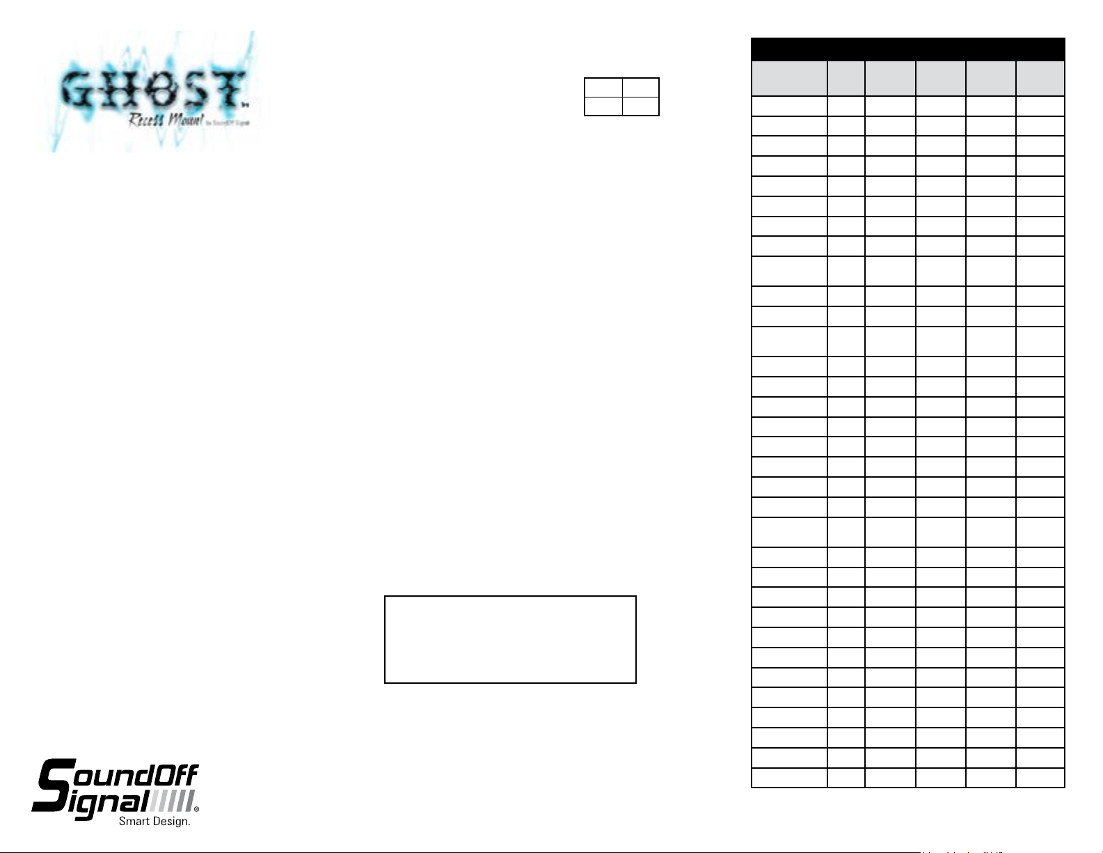
Flash Patterns
Pattern Name 1 Light
1. Quint
2. Warp
3. Inter-Cycle Flash
4. Double Flash
5. Quad Flash
6. PowerPulse™
7. RoadRunner™
8. Q-Switch™
9. RoadRunner™
Steady Burn
10. Quad Steady Burn
11. E-Ideal Single Flash
12. E-Ideal Double
Flash
13. Quad2 Flash
14. Double2 Flash
15. X-Warp
16. X-Double
17. PowerRunner
18. LCR Quint
3
19. Warp
20. Ultra Warp
21. Thunder &
Lightning
22. Lite Speed
23. SuperSonic
24. LCR Lite Speed
25. SuperSonic Ultra
26. Tempo Shift
27. Tempo Shift Warp
28. SBE2
2
29. C
2
30. U
31. Ultra Glow
32. Cyclone
33. Chameleon
x x x 70
x x x 350
x x
x x x 70
x x x 80
x x x 180
x x x 113
x x
x x 113
x x 80
x x x 200
x x x 146
x x x 67
x x x 95
x x x
x x x
x x x
x x x 545
x x
x x x 85
x x 170
x x x
x x x
x x x
x x x
x x x 67
x x x 200
x x x 176
x x x
x x x
x x x
Alternating 2
Lights
Silmultaneous 2
Lights
X-Pattern
4 Lights
x
x
F.P.M.
(Flashes /
Minute)
1.800.338.7337 / www.soundoffsignal.com
ECPGHKC1B(xx) 11.12
 Loading...