

Page 1

SOUNDCRAFT
RM100
USER GUIDE
Page 2

Harman International Industries Ltd. 1994, 1997
All rights reserved
Parts of the design of this product may be protected by worldwide patents.
Part No. ZM0079 Issue 3
Soundcraft is a trading division of Harman International Industries Ltd.
Information in this manual is subject to change without notice and does not
represent a commitment on the part of the vendor. Soundcraft shall not be liable
for any loss or damage whatsoever arising from the use of information or any
error contained in this manual, or through any mis-operation or fault in hardware
contained in the product.
No part of this manual may be reproduced, stored in a retrieval system, or
transmitted, in any form or by any means, electronic, electrical, mechanical,
optical, chemical, including photocopying and re co rd ing, fo r a ny purpose
without the express written permission of Soundcraft.
It is recommended that all maintenance and servic e on the pro duc t should be
carried out by Soundcraft or its authorised agents. Soundcraft cannot accept any
liability whatsoever for any loss or damage caused by service , ma inte na nc e or
repair by unauthorised personnel.
Harman International Industries Ltd.
Cranborne House
Cranborne Industrial Estate
Cranborne Road
Potters Bar
Herts.
EN6 3JN
England
Tel: 0707 665000
Fax: 0707 660482
Page 3

&RQWHQWV
Introduction 1.1
Introduction 1.2
Precautions and Safety Instructions 1.4
Installation 2.1
Installation 2.2
Connections 2.3
Module Block Diagrams 3.1
Mic/Line Input Module 4.1
Description & Operation 4.2
Specifications 4.4
Stereo Input Module 4.5
Description & Operation 4.6
Specifications 4.8
Telco Input Module 4.9
Description & Operation 4.10
Specifications 4.12
Master Module 4.13
Description & Operation 4.14
Specification 4.18
Meterbridge 4.19
Stereo Source Select Module 4.20
Page 4

Appendices A.1
Dimensions A.2
Glossary A.3
Warranty A.4
CPS150 Power Supply P.1
Page 5

Introduction
Introduction
Precautions and Safety Instructions
Introduction 1.1
Page 6

,QWURGXFWLRQ
The RM100 is designed as a simple-to-operate on-air Radio console. Front panel
controls are kept to a minimum to give a clear and uncluttered appearance while
providing sufficient flexibility and choice to meet individual requirements.
The design of the console allows for desktop mounting or drop-through mounting
into a table-top.
A choice of input modules and frame sizes is available, with the option of a script
tray on the larger frame sizes.
The console features illuminated switches throughout for clear operation and a
choice of high quality carbon or conductive plastic faders.
Frame Sizes
Module Options
Metering
The RM100 is available in three frames sizes:
• 8 Inputs + Master
• 12 Inputs + Master
• 20 Inputs + Master
Frames may be fitted with a choice of modules as follows:
• Mono Mic/Line Input module
• Stereo Line Input module
• Telco Input module
• Master Broadcast Module
• Master Production Module (with PGM and AUD Master Faders)
Two meterbridge styles are available.
The standard version comprises:
• a single pair of VU meters (PPM meters optional)
• two pairs of VU meters on the 20 input frame
The alternative version comprises:
• a single pair of VU meters (PPM meters optional)
• two pairs of VU meters on the 20 input frame
• 4-digit timer module
• cue loudspeaker
1.2 Introduction
Page 7

Power Supplies
• 8, 12 and 20 input frames CPS150 power supply
Introduction 1.3
Page 8

3UHFDXWLRQVDQG6DIHW\,QVWUXFWLRQV
General Precautions
Caution!
Handling and Transport
Power Supplies & cables
Avoid storing or using the mixing console in conditions of excessive heat or cold,
or in positions where it is likely to be subject to vibration, dust or moisture. Do not
use any liquids to clean the fascia of the unit: a soft dry brush is ideal. Use only
water or ethyl alcohol to clean the trim and scribble strips. Other solve nts may cause
damage to paint or plastic parts.
Avoid using the console close to strong sources of electromagnetic radiation (e.g.
video monitors, highpower electric cabling): this ma y cause degradation of the audio
quality due to induced voltages in connecting leads and chassis. For the same
reason, always site the power supply away from the unit.
In all cases, refer servicing to qualified personnel.
The console is supplied in a strong carton. If it is necessary to move it any distance
after installation it is recommended that this packing is used to protect it. Be sure
to disconnect all cabling before moving. If the console is to be regularly mov ed we
recommend that it is installed in a foamlined flightcase. At all times avoid applying
excessive force to any knobs, switches or connectors.
Always make sure that the power supply unit (PSU) has been set to the same voltage
as the mains supply
Warning!
Always use the power supply and cable supplied with the mixer: the use of
alternative supplies may cause damage and voids the warranty; the extension of
power cables may result in malfunction of the mixing console.
Always switch the power supply off before connecting or
disconnecting the mixer power cable, removing of installing
modules, and servicing. In the event of an electrical storm, or large
mains voltage fluctuations, immediately switch off the PSU and
unplug from the mains.
Always ensure that you use the correct PSU for your mixer. The RM100 uses a
CPS150 power supply for the 8, 12 and 20 input frames.
1.4 Introduction
Page 9

Signal Levels
It is important to supply the correct input levels to the console, otherwise signalto
noise ratio or distortion performance may be degraded; and in extreme cases,
damage to the internal circuitry may result. Likewise, on all balanced inputs avoid
sources with large commonmode DC, AC or RF voltages, as these will reduce the
available signal range on the inputs. Note that 0dBu = 0.775V RMS.
The microphone inputs are designed for use with balanced low impedance (150 or
200 ohms) microphones.
Caution!
DO NOT use unbalanced microphones or battery powered
condenser microphones without isolating the +48V phantom power:
degraded performance or damage to the microphone may result.
The sensitivity of the Mic inputs is variable from -20dBu to -70dBu, with a
maximum input level of +6dBu. The Line Input sensitivity is variable from -48dBu
to +2dBu with a maximum input level of +28dBu.
The Stereo and Telco input sensitivity is variable from -12dBu to +9dBu, with a
maximum input level of +28dBu.
The main outputs of the console (PGM, AUD and MONO) are balanced at a nominal
level of 0dBu, with the option of -10dBV on the AUD output by changing internal
jumpers. Maximum output level is +26dBu into 600 ohms.
The Telco mix-minus output is balanced at a nominal level of 0dBu with a maximum
output level of +20dBu into 600 ohms.
Introduction 1.5
Page 10

1.6 Introduction
Page 11

Installation
Installation 2.1
Page 12

,QVWDOODWLRQ
The RM100 is designed for reliability and high performance, and is built to the
highest standards. Whilst great care has been taken to ensure that installations are
made as troublefree as possible, care take n at this stage, followed b y correct setting
up will be rewarded by a long life and reliable operation.
Wiring Considerations
Power Supply
Warning!
A For optimum performance it is essential for the earthing system to be clean and
noisefree, as all signals are referenced to this earth. A central point should be
decided on for the main earth point, and all earths should be ’star-fed’ from this
point. It is recommended that an individual earth wire be run from each electrical
outlet, back to the system star point to p rovide a safety earth reference for each piece
of equipment.
B Install separate mains outlets for the audio equipment, and feed these
independently from any other equipment.
C Avoid locating mains distribution boxes near audio equipment, especially tap e
recorders, which are very sensitive to electromagnetic fields.
D Where possible ensure that all audio cable screens and signal earths are
connected to ground only at their source.
Always ensure that you use the correct PSU for your mixer. The RM100 uses a
CPS150 power supply for the 8, 12 and 20 input frames.
Before switching on your RM100 console, check that the mains
voltage selectors on the power supply unit is set to the correct
mains voltage for your area, and that the fuse is of the correct rating
and type. This is clearly marked on the case of the power supply.
Do not replace the fuse with any other type, as this could become a
safety hazard and will void the warranty.
2.2 Installation
Page 13
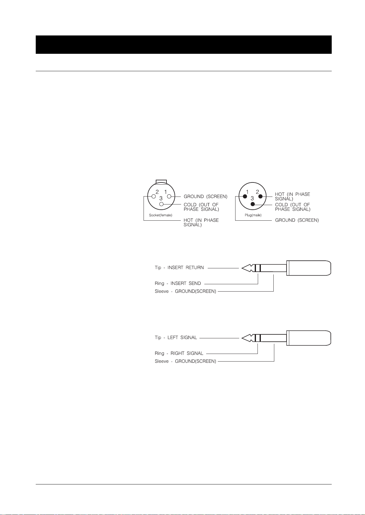
&RQQHFWLRQV
Wiring conventions
1
The RM100 uses various different types of aud io connector: 3-pin XLR ,
⁄
" 3-pole
4
jacks and ‘D’ type connectors. This section describes how to connect external
equipment to the console. Correctly-made cables of the proper type will ensure
peak performance from your console.
MICROPHONE INPUTS
& LINE INPUTS
1
/4" ‘A’ Gauge Stereo Jack Plug used as an insert point:
PGM, AUD, MONO
& C/F OUTPUTS
1
/4" ‘A’ Gauge Stereo Jack Plug used as stereo output:
Headphones and Control Room Monitors
The following pages give details of the connectors which are not covered by the
diagram above.
Installation 2.3
Page 14

Stereo Input Module
Telco Input Module
Input 2 + Remotes (15-pin ‘D’ type connector)
Pin 1 Chassis
Pins 2, 9 Machine 1 Start
Pins 3, 10 Machine 1 Stop
Pins 4, 11 Machine 2 Start
Pins 5, 12 Machine 2 Stop
Pins 6, 13 Input 2 Right -,+
Pin 7 Ground
Pins 8, 15 Input 2 Left -,+
Pin 14 Ground
Remotes (15-pin ‘D’ type connector)
Pin 1 Chassis
Pin 2 Divert n/c
Pin 3 Divert n/o
Pins 9,10 Divert common
Pin 8 Insert Return
Pin 15 Insert Send
Master Module
Pins 7, 14 Ground
Pins 4, 5, 6, 11, 12, 13 no connection
External Inputs (15-pin ‘D’ type male connector)
Pin 1 Chassis
Pin 2 External Input 1 Left +
Pin 3 External Input 1 Right +
Pin 4 External Input 2 Left +
Pin 5 External Input 2 Right +
Pin 6 Ground
Pin 7 External Input 3 Left
Pin 8 External Input 3 Right
Pin 9 External Input 1 Left Pin 10 External Input 1 Right Pin 11 External Input 2 Left Pin 12 External Input 2 Right Pin 13 Ground
Pin 14 External Input 4 Left
Pin 15 External Input 4 Right
2.4 Installation
Page 15

Master Module
Remote (9-pin ‘D’ type connector)
Pin 1 C/Room Mute Contact 1 common
Pin 2 C/Room Mute Contact 1 n/o
Pin 3 C/Room Mute Contact 2 common
Pin 4 C/Room Mute Contact 2 n/o
Pin 5 no connection
Pin 6 no connection
Pin 7 no connection
Pin 8 no connection
Pin 9 no connection
Guest H/P + Rev T/B (9-pin ‘D’ type connector)
Pin 1 Chassis Ground
Pin 2 Guest Headphones Left Ground
Pin 3 Guest Headphones Left Signal
Pin 4 Guest Headphones Right Ground
Pin 5 Guest Headphones Right Signal
Pin 6 Audio Ground
Pin 7 Reverse Talkback Input
Pin 8 Reverse Talkback Control Signal
Pin 9 no connection
Installation 2.5
Page 16

2.6 Installation
Page 17

Module Block Diagrams
Module Block Diagrams 3.1
Page 18

3.2 Module Block Diagrams
Page 19

Mic/Line Input Module
Description & Operation
Specification
Mic/Line Input Module 4.1
Page 20
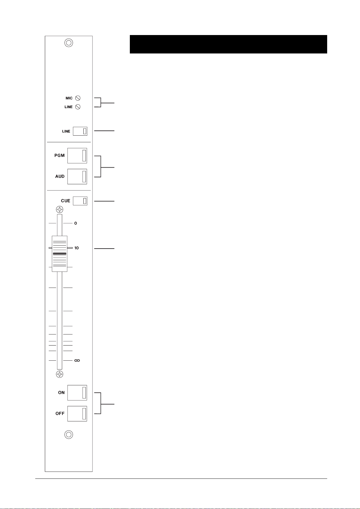
0LF/LQH,QSXW0RGXOH
Input Stage
Two inputs, one microphone level and one line level, are provided to the module
1
on separate XLR connectors. The MIC input has +4 8V Phantom Powe r ava ilable ,
which may be activated by an internal jumper.
1
Each input has individual
2
5
3
adjusted using a small screwdriver through the front panel.
The
LINE
switch selects the Line Input socket when depressed and the Mic
2
Input socket when released. An LED in the switch glows red when the Line Input
is selected.
Note that phantom power is not connected to the LINE XLR, even when selected
on the MIC input.
Cueing
The
CUE
switch works in conjunction with a microswitch on the Fader.
3
Pressing the electronically latching CUE switch routes the pre-fa de, pre-mute signal
to the stereo Cue bus. This signal appears on the Headphones or Cue Speaker (if
fitted) and can be selected onto the main monitors by pressing the AUTO CUE
button on the Master module.
GAIN
control via a multiturn preset which may be
4
Cue may be cancelled in three ways:
• Pressing the CUE switch a second time
• Moving the fader away from rest at infinity
• Pressing the ON button (see below)
CUE cannot be selected when the module is ON, and the Fader lifted away from
the end stop. If the Fader is fully down, CUE may be selected in the normal way.
Output Control
4
The smoothaction, 100mm
up position. The 10 scale marking corresponds to a nominal unity gain.
There is a microswitch attached to the Fader which detects when it is in the fully
down position. This microswitch affects the ON and CUE functions which are
described in this section.
5
6
The mono Fader output may be routed to a choice of two stereo mix busses,
PGM and AUD. These switches are mechanically latching and have an integral
LED to show when the bus is selected. The output is only ac tive whe n the module
is switched ON (see below).
FADER
gives a gain of 10dB when it is in the fully
4.2 Mic/Line Input Module
Page 21

6
The output from the module is controlled by the ON and OFF switches, in
conjunction with the fader microswitch.
If the Fader is fully down:
Pressing the ON switch prepares the module to be active, and lights the red LED in
the ON switch at half brightness. The signal becomes active as soon as the Fader
is moved away from the infinity position, and the LED changes to full brightness.
If the Fader is lifted:
Pressing the ON switch immediately activates the module, and the LED lights at
full brightness.
Pressing the OFF switch will always turn the module off.
Send/Return
A pre-fade, pre-talkback Insert Point is provided on a 1/4" 3-pole jack on the rear
panel. This allows for the use of an effects mac hine to be a dded to the mono input
channel, e.g. voice processor, echo. The send and return lines are unbalanced and
care will need to be taken with the length and type of leads which are used.
Rear Connector Panel
The Insert is bypassed when no jack is connected.
Jumper Options
J1 Fit in position ‘B’ to enable +48V Phantom Power to the MIC input XLR.
J2 Fit to enable the pre-fade module output to the Talkback Mix bus which
feeds the Telco module clean feed output.
Mic/Line Input Module 4.3
Page 22

Specifications
Microphone Input
Electronically balanced
Input Impedance >2.2kΩ
Maximum I/P level +6dBu
Sensitivity Range -70dBu to -20dBu
CMRR > 100dB
EIN -128dBu, 150Ω source
Line Input
Electronically balanced
Input Impedance >20kΩ
Input Range -48dBu to +2dBu
General
Patch Send Level -10dBu unbalanc e d
THD < 0.02%
4.4 Mic/Line Input Module
Page 23

Stereo Input Module
Description & Operation
Specification
Stereo Input Module 4.5
Page 24

6WHUHR,QSXW0RGXOH
Input Stage
Two stereo Line Inputs are provided to the module, one on XLR connectors and
1
2
5
one on the multipin connector.
1
The input has individual gain controls for Right and Left via multiturn presets
which may be adjusted using a small screwdriver thro ugh the front panel. The gain
range allows matching to -10dBV or +4dBu sources.
2
The B switch selects Input B on the multipin connector when depresse d and the
Input A XLR connectors when released. An LED in the switch glows red when
Input B is selected. The switch also selects the corresponding pair of start/stop
remote contacts (see below).
Cueing
3
3
Pressing the electronically latching CUE switch routes the pre-fa de, pre-mute signal
to the stereo Cue bus. This signal appears on the Headphones or Cue Speaker (if
fitted) and can be selected onto the main monitors by pressing the AUTO CUE
button on the Master module.
Cue may be cancelled in three ways:
The
CUE
switch works in conjunction with a microswitch on the Fader.
4
• Pressing the CUE switch a second time
• Moving the fader away from rest at infinity
• Pressing the ON button (see below)
CUE cannot be selected when the module is ON, and the Fader lifted away from
the end stop. If the Fader is fully down, CUE may be selected in the normal way.
Output Control
4
The smooth action, 100mm
up position. The ‘10’ scale marking corresponds to a nominal unity gain.
There is a microswitch attached to the Fader which detects when it is in the fully
down position. This microswitch affects the ON and CUE functions which are
described in this section.
FADER
gives a gain of 10dB when it is in the fully
5
The Fader output may be routed to a choice of two stereo mix busses, PGM and
AUD. These switches are mechanica lly latching and have an integral LED to show
6
when the bus is selected. The output is only active when the module is switched
ON (see below).
4.6 Stereo Input Module
Page 25

6
The output from the module is controlled by the ON and OFF switches, in
conjunction with the fader microswitch.
If the Fader is fully down:
Pressing the ON switch prepares the module to be active, and lights the red LED in
the ON switch at half brightness. The signal becomes active as soon as the Fader
is moved away from the infinity position, and the LED changes to full brightness.
If the Fader is lifted:
Pressing the ON switch immediately activates the module, and the LED lights at
full brightness.
Pressing the OFF switch will always turn the module off.
Remotes
The multipin connector on the rear panel provides individua l sta rt/stop c omma nds
for each stereo input, as selected by the B switch. The outputs are isolated relay
contact closures.
Rear Connector Panel
Jumper Options
J1 Fit in position ‘B’ for latching start
Stereo Input Module 4.7
Page 26

Specifications
Line Inputs
Electronically balanced
Input Impedance >40kΩ
Maximum I/P level +28dBu
Sensitivity Range -12dBu to +9dBu
EIN -85dBu, 600Ω source
General
THD < 0.02%
4.8 Stereo Input Module
Page 27

Telco Input Module
Description & Operation
Specification
Telco Input Module 4.9
Page 28

7HOFR,QSXW0RGXOH
Input Stage
The Telco module must be conected to the telephone system via a Telephone
1
2
3
Hybrid.
1
The balanced
which the output from an external Telephone Hybrid may be plugged. A gain
control is provided via a multiturn preset which may be adjusted using a small
screwdriver through the front panel.
LINE
Input is a female XLR connector on the rear panel into
2
The balanced
panel which may be plugged into the input of an external Telephone Hybrid. The
6
4
Clean Feed signal (also known as Mix Minus) is the programme output minus the
telephone signal. A multiturn preset is accessible through the front panel to allow
optimum nulling of the local phone signal to be set.
Output level may be set at a nominal 0dBu or -10dBV by means of an internal
jumper.
The
DIVERT
3
to connect to an external Telephone Hybrid to allow a caller to be diverted to or
from, for example, a standard telephone handset. These switch contacts are
provided on the Remotes connector.
C/F
(Clean Feed) output is a male XLR connector on the rear
switch with integral LED provides an isolated switch changeover
5
Cueing
The
CUE
switch works in conjunction with a microswitch on the Fader.
4
Pressing the electronically latching CUE switch routes the pre-fa de, pre-mute signal
to the stereo Cue bus. This signal appears on the Headphones or Cue Speaker (if
fitted) and can be selected onto the main monitors by pressing the AUTO CUE
button on the Master module.
Cue may be cancelled in three ways:
• Pressing the CUE switch a second time
• Moving the fader away from rest at infinity
• Pressing the ON button (see below)
CUE cannot be selected when the module is ON, and the Fader lifted away from
the end stop. If the Fader is fully down, CUE may be selected in the normal way.
Output Control
7
5
The smooth action, 100mm
up position. The ‘10’ scale marking corresponds to a nominal unity gain.
There is a microswitch attached to the Fader which detects when it is in the fully
down position. This microswitch affects the ON and CUE functions which are
described in this section.
When CUE is active the caller will hear the signal on the talkback bus, enabling
two-way off-air communication.
4.10 Telco Input Module
FADER
gives a gain of 10dB when it is in the fully
Page 29

6
The Fader output may be routed to a choice of two stereo mix busses, PGM and
AUD. These switches are mechanica lly latching and have an integral LED to show
when the bus is selected. The output is only active when the module is switched
ON (see below).
7
The output from the module is controlled by the ON and OFF switches, in
conjunction with the fader microswitch.
If the Fader is fully down:
Pressing the ON switch prepares the module to be active, and lights the red LED in
the ON switch at half brightness. The signal becomes active as soon as the Fader
is moved away from the infinity position, and the LED changes to full brightness.
If the Fader is lifted:
Pressing the ON switch immediately activates the module, and the LED lights at
full brightness.
Pressing the OFF switch will always turn the module off.
Remotes
Rear Connector Panel
The Remotes connector provides the following facilities:
• Insert Point - unbalanced, which may be bypasse d by an internal jumper.
• Divert - isolated single-pole switch changeover.
Jumper Options
J1 Position B enables Insert Point.
J2 Position A selects 0dBu Clean Feed output, Position B selects -10dBV.
Telco Input Module 4.11
Page 30

Specifications
Line Inputs
Electronically balanced
Input Impedance >40kΩ
Maximum I/P level +28dBu
Sensitivity Range -12dBu to +9dBu
Clean Feed Output
Electronically balanced
Output Impedance < 75Ω
Output Level 0dBu or -10dBV, jumper selectable
4.12 Telco Input Module
Page 31

Master Module
Description & Operation
Specification
Master Module 4.13
Page 32

1
12
2
3
4
5
7
6
8
RM100
9
10
11
4.14 Master Module
Page 33

0DVWHU6HFWLRQ
Main Outputs
The Master module incorporates the mix amps outputs for the PGM and AUD
busses, plus a MONO output which can be sourced from the PGM or AUD busses
as selected by the MONO OUTPUT SOURCE switches (see below). These three
outputs are electronically balanced on male XLR conne c tors on the rear pa ne l.
Output levels are nominally 0dBu, but the AUD outputs may be changed via internal
jumpers to give -10dBV.
Master Faders are available as an option for the PGM a nd AUD outputs.
External Inputs
There are four stereo external available on a 15-pin male ‘D’-type connector on the
rear panel. Inputs 1 & 2 are electronically balanced at 0dBu and Inputs 3 & 4 are
unbalanced at -10dBV.
Mono Output
The MONO OUTPUT SOURCE switches select either one or both of PGM
1
or AUD as the source for the MONO output. Integral LED indicators illuminate
when the source is selected.
Monitoring
Separate source selectors feed the Guest Headphones, Co ntrol Room Monitors and
the Presenter’s Headphones
Guest Headphones
The LEVEL control sets the output level to the stereo Guest Headphone s output.
2
The source is normally PGM.
Normally the Cue signal appears on the Presenter’s Hea phones and Cue Speaker
3
in the meterbridge (when fitted). Pressing AUTO CUE routes an active CUE to
the Guest Headphones, replacing the normal PGM source. When the CUE is
released the headphones return to the original source.
Pressing T/B routes the signal from the Talkback Bus directly to the Guest
4
Headphones, replacing the PGM signal. (The Talkback Bus normally carries the
Presenter’s Mic signal via a dedicated Mic/Line input with the Talback jumper
fitted). The PGM signal is restored when T/B is released.
Control Room Monitor
Three SOURCE SELECT switches provide a choice of External Input 1, PGM
5
or AUD as the source for the monitors.
The LEVEL control sets the output level to the stereo C/Room Monitor jack
3
on the rear panel. The outputs are unbalanced.
Master Module 4.15
Page 34

1
12
2
3
4
5
7
6
8
RM100
9
10
11
4.16 Master Module
Page 35

The Control Room Monitors may be muted automatically when local
7
microphones are turned ON and the corresponding Faders opened. The MUTE
LED illuminates to show that a ’Mic Live’ condition has muted the monitors. The
same signal is used to activate a relay which provides two isolated single-pole
contact closures on the 9-pin ‘D’-type REMOTE socket on the rear panel.
Normally the Cue signal appears on the Presenter’s Hea phones and Cue Speaker
8
in the meterbridge (when fitted). Pressing AUTO CUE routes an active CUE to
the Control Room Monitors, replacing the previous source. When the CUE is
switched off the monitor returns to the original source.
Presenter’s Headphones
Six SOURCE SELECT switches provide a choice of External Inputs 1-4, PGM
9
or AUD as the source for the headphones.
The LEVEL control sets the level of the headphone signal.
10
The headphone output is a 3-pole 1/4" jack.
11
The meterbridge is fitted with a pair of VU meters as standard. The METER
12
SELECT switches provide a choice of PGM, AUD or MON (C/Room Monitor) as
the source for the meters. Note that the MON position provides a means of
monitoring the external inputs via the C/Room Monitor source se le ction.
On the larger frame sizes an additional pair of meters may be fitted , and in this case
one pair of meters will always display the PGM output.
Power Input
The 5way locking POWER connector is the power input to the console. The
console requires +17V, 17V and +48V.
Rear Connector Panel
Master Module 4.17
Page 36

Specifications
PGM, AUD & Mono
Max. output +26dBu into 600Ω
Output impedance <75Ω
General
THD < 0.02%
Crosstalk < -80dB @ 20kHz
4.18 Master Module
Page 37

0HWHUEULGJH
Two meterbridge styles are available. The following facilities are provided as
standard:
a single pair of VU meters (PPM meters optional). These display the level of
1
the source selected by the METER SELECT switches, and can be calibrated by
means of two screwdriver presets on the Master Panel (see earlier in this chapter).
The following facilities are only available on the optional meterbridge :
4-digit TIMER MODULE. This can be programmed by internal jumpers on
2
the stereo modules to start automatically when the stereo channel is activated, or
controlled manually by the local switches.
The CUE SPEAKER and associated LEVEL control monitor the output of the
3
CUE bus
213
Master Module 4.19
Page 38

SOURCE A
1
2
3
4
6WHUHR6RXUFH6HOHFW0RGXOH
The Stereo Source Select module provides switching from 8 balanced stereo
sources, which are presented on a 38-way male EDAC connector to two independent
balanced stereo outputs on a 15-way male D-type connec tor. Switching is done via
two independent banks of eight switches.
Select Switches
An LED in each switch indicates which switch in each bank is selected. The
switches in each bank are interlocked, i.e. pressing a switch will deselect any othet
switch in the same bank.
5
6
7
8
SOURCE B
1
2
3
4
5
6
7
8
EDAC Connector Pinouts
Pin Signal Pin Signal
A 1 L+ X Chassis Ground
B 1 L- Y Chassis Ground
C 1 R+ Z 5 L+
D 1 R- AA 5 LE 2 L+ BB 5 R+
F 2 L- CC 5 RH Not used DD 6 L+
J 2 R+ EE 6 LK 2 R- FF 6 R+
L 3 L+ HH 6 RM 3 L- JJ 7 L+
N 3 R+ KK 7 LP 3 R- LL Not used
R 4 L+ MM 7 R+
S 4 L- NN 7 RT 4 R+ PP 8 L+
U 4 R- RR 8 LV Chassis ground SS 8 R+
W Chassis ground TT 8 R-
4.20 Master Module
Page 39

15-Way D-type Pinout
Pin Signal Pin Signal
1 Chassis ground 9 Source A L+
OUTPUT B
OUTPUT A
+
2 Source A L- 10 Not used
3 Not used 11 Source A R+
4 Source A R- 12 Not used
5 Not used 13 Source B L+
6 Source B L- 14 Not used
7 Not used 15 Source B R+
INPUTS
8Source B R-
Master Module 4.21
Page 40

4.22 Master Module
Page 41

Appendices
Dimensions A.2
Glossary A.3
Warranty A.4
Appendices A.1
Page 42

Dimensions
9.68" (246mm)
MODULES AT 10
14.76" (375mm)
17.16" (436mm)
8 IP CHASSIS = 17.01" (432mm)
12 IP CHASSIS = 22.52" (572mm)
20 IP CHASSIS = 33.54" (852mm)
o
3.27" (83mm)
8 IP CHASSIS = 15.35" (390mm)
12 IP CHASSIS = 20.87" (530mm)
20 IP CHASSIS = 31.89" (810mm)
8 IP CHASSIS = 16.54" (420mm)
12 IP CHASSIS = 22.05" (560mm)
20 IP CHASSIS = 33.07" (840mm)
A.2 Appendices
Page 43

Glossary
Attenuation The reduction of a signal level. The attenuation is usually measured in dB.
Clipping The onset of severe distortion in the signal path, usually caused by the peak signal
voltage being limited by the circuit’s power supply voltage.
CMRR Common Mode Rejection Ratio. It is the ratio of the extent to which a differential
amplifier will cancel noise, which is present on both inputs, compared to its ability
to amplify the wanted signal.
dB (decibel) A ratio of two voltages or signal levels, expressed by the equation
V
1
(
⁄
dB=20LOG
Adding the suffix ’u’ denotes that the signal is relative to 0.775V RMS. Adding
the suffix ’v’ denotes that the signal is relative to 1V RMS.
EIN Equivalent Input Noise. It is the ratio of output no ise to th e gain. It describes the
level of noise which would need to be fed into an ideal amplifier to produce the
measured output noise.
Gain The degree of amplification, or attenuation applied to a signal.
10
).
V
2
Hybrid A device which allows a telephone line to be connec ted to a broadcast desk in such
a way that the caller may hear the programme output without the caller’s voice being
re-introduced on to the phone line which would cause unwanted fee dback.
LED Light Emitting Diode.
TELCO TELephone COmmunication.
THD Total Harmonic Distortion.
Appendices A.3
Page 44

Warranty
1 Soundcraft means Soundcraft Electronics Ltd.
End User means the person who first puts the equipment into regular operation.
Dealer means the person other than Soundcraft (if any) from whom the End
User purchased the Equipment, provided such a person is authorised for this
purpose by Soundcraft or its accredited Distributor.
Equipment means the equipment supplied with this manual.
2 If within the period of twelve months from the date of delivery of the Equipment
to the End User it shall prove defective by reason only of faulty materials and/or
workmanship to such an extent that the effectiveness and/or usability thereof is
materially affected the Equipment or the defective component should be returned
to the Dealer or to Soundcraft and subject to the following conditions the Dealer
or Soundcraft will repair or replace the defective components. Any components
replaced will become the property of Soundcraft.
3 Any Equipment or component returned will be at the risk of the End User whilst in
transit (both to and from the Dealer or Soundcraft ) and postage must be prepaid.
4 This warranty shall only be available if:
a) the Equipment has been properly installed in accordance with instructions
contained in Soundcraft’s manual; and
b) the End User has notified Soundcraft or the Dealer within 14 days of the
defect appearing; and
c) no persons other than authorised representatives of Soundcraft or the Dealer
have effected any replace ment of parts mai ntenance adjust ments or repairs to th e
Equipment; and
d) the End User has used the Equipment only for such purposes as Soundcraft
recommends, with only such operating supplies as meet Soundcraft’s
specifications and otherwise in all respects in accordance Soundcraft’s
recommendations.
5 Defects arising as a result of the following are not covered by this Warranty: faulty
or negligent handling, chemical or electro-chemical or electrical influences,
accidental damage, Acts of God, neglect, deficiency in electrical power,
air-conditioning or humidity control.
6. The benefit of thi s Wa rr anty may not be assig ned by the End User.
7. End Users who are consumers should note their rights under this Warranty are in
addition to and do not affect any other rights to which they may be entitled
against the seller of the Equipment.
A.4 Appendices
Page 45

CPS150 Power Supply
CPS150 Power Supply 43
Page 46

CPS150 User & Technical Manual
IMPORTANT: PLEASE READ THIS MANUAL CAREFULLY
BEFORE CONNECTING YOUR SOUNDCRAFT CPS150 POWER
SUPPLY TO THE MAINS FOR THE FIRST TIME.
WARNING SYMBOLS
For your own safety and to avoid invalidation of the warranty
all text marked as this paragraph should be read carefully.
FOR UK USERS ONLY
IMPORTANT WARNING
THIS APPLIANCE MUST BE EARTHED
The wires in the mains lead are coloured in accordance with the following code:
Green and Yellow:
Blue:
Brown:
As the colours of the wires in the mains lead may not correspond with the
coloured markings identifying the terminals in your plug, proceed as follows:
The wire which is coloured Green and Yellow must be connected to the
•
terminal in the plug which is marked with the letter E or by the earth symbol.
The wire which is coloured Blue must be connected to the terminal in the plug
•
which is marked with the letter N or coloured Black.
The wire which is coloured Brown must be connected to the terminal in the
•
plug which is marked with the letter L or coloured Red.
Earth
Neutral
Live
CPS 150 P.1
Page 47

Introducing the CPS150
The CPS150 is a linear power supply which, like other linear supplies, produces
DC voltages by rectifying, smoothing and regulating AC voltages from the
secondary windings of a mains transformer.
In regulating these voltages there is some heat generated, the dissipation of
which is achieved through a ventilated cover.
The CPS150 is designed to be free standing or it can be installed in a 19" rack.
For rack mounting, an optional fron t panel provided with the necessary fixing
holes can be obtained from Soundcraft (Part No. PP2288). Refer to the section
"RECOMMENDATIONS FOR INSTALLATION" for details.
LED indication is provided on the front panel to show indication of operation
of all regulating circuits.
SAFETY APPROVAL: HD 195 S6 TYPE TESTED
This manual covers the CPS 150 unit, that has been type tested and conforms to
the CENELEC Harmonised Document HD195 S6, consisting of IEC 65
(1985)ed 5 and BS 415 1990, with CENELEC deviations.
EMC CONDUCTED EMISSION
Certification of Conformity has been received for both:
USA Statutory Emission Requirements (FCC CFR47 Part 15J, A and B)
German Statutory Emission Requirements (VDE0871, A and B)
P.2 CPS 150
Page 48

Mains Voltage Selection
Special attention should be given to the following information:
This unit is capable of operating over a wide range of mains voltages by means
of a comprehensive set of selectable voltage settings. It is important to ensure
that the correct voltage setting has been selected for the level of local mains
voltage supply, for safe, uninterrupted operation of the unit.
A COVER PLATE is secured to the back panel over the VOLTAGE
SELECTION switches. A cut out in one corner of the cover plate indicates one
of the mains voltages. It is essential that the MAINS VOLTAGE displayed by
the cover pla te correspon ds to both the LOC AL MAINS VOLT AGE and the
VOLTAGE SELECTION switches position.
Do not change the voltage setting without first unplugging the
mains lead.
There are two MAINS VOLTAGE SELECTION switches at the rear of the
unit, Voltage selection is achieved by moving the switches using a screwdriver
blade, into the correct positions, as shown by the symbols above the switches In
this way the unit is set up for operation at one of the following ranges of mains
supply:
NOMINAL VOLTAGE
Vrms AC
240 216-264
OPERATING VOLTAGE RANGE
Vrms AC
220 198-242
120 (115) 108-132
100 NORM. 90-110
NOTE: The cover plate must be replaced after setting of the
VOLTAGE SELECTION
switches.
CPS 150 P.3
Page 49

Replacing Mains Fus e
In the event of incorrect switching of the mains voltage selectors, a mains power
surge or underrated fuse value, the mains fuse in the front panel will blow and
the CPS150 will not function. Switch the ON/OFF switch back to the OFF
position. Check the fuse and replace if necessary; also check that the voltage
selection is correct for the mains supply level before switching the unit ON
again.
In the event of repeated failure of the mains fuse consult the Soundcraft dealer
from where the unit was purchased.
TO AVOID RISK OF FIRE
REPLACE ONLY WITH THE
CORRECT VALUE FUSE, AS
INDICATED ON THE UNIT
THIS UNIT CONTAINS NO USER SERVICE-ABLE PARTS.
REFER ALL SERVICING TO A QUALIFIED SERVICE ENGINEER,
THROUGH THE APPROPRIATE SOUNDCRAFT DEALER.
OUTPUT CPS 150
17V @ 1.25A
48V @ 125mA
PRODUCT COMPLIES WITH
Voltage selector Cover Plates Indication
240V
UK
EUROPEAN
UK
EUROPEAN
220V
SAFETY STANDARD HD195 S6
AMERICAS
120V
P.4 CPS 150
Page 50

Recommendations for Installation
The CPS150 power supply can be prov ided with an optional front panel with
fixing holes for 19" rack-mounting and will occupy 2U of rack space.
Location
Ventilation
As with any power supply that contains a large mains voltage transformer, it is
preferable to provide a degree of physical isolation of the unit from other
electronic equipment, particularly that which carries low level audio signals, to
avoid any possible hum pick-up. For this reason the unit is provided with a long
(3.0 metres) output cable to enable it to be positioned away from the mixing
console.
For the same reason, when rack-mounting it is preferable to avoid locating the
unit near to sign al pr ocessing equip me nt .
It should be noted that if a complete rack contain ing a CPS150 unit is to be
operated from a different mains supply level, then the unit should be withdrawn
from the rack in order to reselect the mains voltage setting, at the same time as
resetting any other equipment.
The other important consideration when rack-mounting the unit is the need for
natural convection of air over the heatsink cooling fins.
Good ventilation below the unit, in the floor or back of the rack, and similarly
above the unit, at the top of the rack, will ensure a path for continuous air flow.
Other equipment in the rack which is known not to produce a significant amount
of heat should be mounted below the unit. Equipment that also relies on good
air flow within the rack (i.e.. most power amplifiers and other power supplies)
should be give n du e con si dera ti on an d some s pace sho uld be pr ov ided be twee n
such units and between these and the CPS150 unit. Forced convection, by means
of a fan-tray, may be desirable in this situation.
Free standing
The CPS150 is designed to operate as a free-standing unit without requiring any
special cooling arrangement, but should not be allowed to be accidentally or
deliberate ly covered in any way.
Earthing
Finally, some consideration should be given to the earthing arrangement of the
system at the centre of whi ch are the console an d the CPS150. Th e console
chassis is earthed, to the mains earth, via the power supply. When rack-mounting
the CPS150 care should be taken to avoid any possible ’ground loop s’ in the
system which would introd uce audible hum to otherwise cle an audio signals.
Ground loops may oc cur where signal processing equipme nt, patched to the
console, has its signal earth commoned to the equipment chassis. The ground
loop is formed if this chassis and the CPS150 chassis are in electrical contact
through the fixing rails they share in the rack.
W A R N I N G
UNDER NO CIRCUMSTANCES SHOULD THE MAINS EARTH
BE DISCONNECTED FROM THE CPS150 POWER SUPPLY UNIT
CPS 150 P.5
Page 51

Optional Rackmount fixing
• Remove the four front cover fixing screws.
• Place the rack mounting panel over the CPS 150.
• Secure the rack mounting panel to the CPS 150, fitting two screws to the top,
and one to each side of the unit.
General Precautions
As with all electrical/electronic equipment some care should be taken when
handling this unit. Avoid general mishandling and do not drop. Avoid storage
and operation in dus t y locations and do not ex po se to co rr os i v e atmospheres.
TO AVOID RISK OF FIRE DO NOT EXPOSE
THIS UNIT TO RAIN OR MOISTURE.
Retain all packaging for transportation in the event of the unit requiring
servicing. Retain this manual, along with all other relevant documents, safely.
P.6 CPS 150
Page 52

CPS150 Technical Specification
Mains input voltage range
240/220/120/100 V AC +/-10% @ 50/60 Hz
Rated input power (max.)
100 VA
Mains fuse rating:
T1.0A 120/240 V AC
T2.0A 110/120 V AC(115V)
Outputs
DC Voltage rails Max output current Max noise
+17V 1.25 AMPS -68 dBu
-17V 1.25 AMPS -68 dBu
+48V 0.125 AMPS -80 dBu
NOTE: All voltage current measurements are to be taken at the console end of
the power supply cable
Operating temperature range (ambient)
-10 TO +50 C.
Humidity
Similar unit tested to 92% Relative Humidity at 40 C for 16 Hours. Load
switched between 20% and 100% at regular 30 minute intervals.
Mechanical
Similar unit Drop tested to Military DEF.STAN 07-55 (part 2) Section 1/1.
Overall Dimensions
CHASSIS
HEIGHT: 85mm
WIDTH: (Chassis ) 287mm
DEPTH: 190mm
OPTIONAL FRONT PANEL
HEIGHT: 87mm (2U)
WIDTH: 482mm
WEIGHT:
Excl. Packaging: 4.0Kg
Packed incl. lead: 5.0Kg
:
CPS 150 P.7
Page 53

Circuit Description
Mains Input
The CPS150 is a Linear power supply, the operation of which avoids the
induction of switchin g noise, associated with switch-mode design s, in audio
signal paths. It has been possible to produce a design which is silent in
operation, and which will function over a greatly improved range of mains input
voltages. Additionally, the design of each supply is very similar and of a modular
format that will assist when servicing.
Refer to circuit diagram ED2770 which accompanies this section.
The mains supply is applied to the unit via the 3-pin IEC inlet on the unit back
plate. The earth feed is led directly to the chassis earth stud: AT NO TIME
SHOULD THIS CONNECTION BE BROKEN. The LIVE (black) and
NEUTRAL (white) feeds are led to the double-pole rocker switch on the front
of the unit, so that live and neutral switching to the following circuitry is made
simultaneously.
From this switch, the neutral feed is led directly to the MAINS PCB. The live
feed passes through the mains fuse (T1.0A 250V: 240V/220V or T2.0A 250V:
120V/100V) situated in the fuseholder on the front, below the ON-OFF switch,
and from there to the MAINS PCB.
Secondary Circuits
Circuit description
The design of the regulator circuitry is essentially the same for each supply rail,
but with different component values for the different voltage levels and power
requirements of the rails.
Each regulator circuit is fused at the input from the transformer secondary
winding, to protect against an over-current condition, in the event of component
failure in the regulator circuit.
Regulation is achieved using positive, adjustable voltage regulators, each housed
in a standard TO3 package, with the exception of the high voltage regulator for
the +48v rail, which is in a TO220 package.
Each regulator circuit is essentially similar, and the following general
description applies in each case. Component references are given for the +17V
rail as a guide.
The Mains Transformer steps-down the mains voltage to produce the required
alternating voltage across each secondary winding. The appropriat e pair of
lead-outs (same colour) are connected to the REGULATOR PCB. One side of
this secondary feed is led directly to the bridge rectifier BR1, while the other is
routed via the secondary protect ive fuse F1 to the bridge rectifier. The level of
the secondary vo ltage may be mea sured by apply ing an AC voltm eter across the
desired pair of secondary lead-outs.
The voltage waveform between points 3 and 4 is full-wave rectified, and
smoothed by a high value electrolytic capacitor C1, so that it appear as a DC
voltage with a small AC ‘ripple’ element. This level may be measured with the
voltmeter set for DC. A 100nF capacitor C2 in parallel with the smoothing
capacitor but closer to the regulator ensures its stability under any condition of
capacitive load.
P.8 CPS 150
Page 54

The regulator REG1 is adjustable, the output voltage being set by a preset
potentiometer in series with a fixed resistance R2 between the adjustment pin
and the "0V" reference. This allows a degree of adjustment equal to:
NOMINAL RATED OUTPUT VOLTAGE (V.dc) -10% +(10% + 0.7 V
(each preset is set and fixed at the factory test stage)
The actual regulated output voltage level is given by:
Vout = Vref x (1 + Radj/R1) + Iadj x R2
~ Vref x (1 + Radj/R1) as Iadj is negligible (~100uA)
The value of R1 is optimised for each regulator type:
For LM338 REGULATORS REG 1, REG 2 R1 = 120R
FOR TL783C REGULATOR R1 = 82R
The electrolytic capacitor C3 in parallel with the adjustment resistor, PR1 + R2
(Radj), improves ripple rejection in the regulator, and also produces a time
constant that causes the DC output of the regulator to rise more slowly when the
unit is switched on. In the case of the +17V and -17 V rails the rise time is about
3 seconds.
The output filter capacitor C4, between the regulator output and the ‘0V’
reference, eliminates ‘ringing’ and a slow regulator shut-down time in the event
of the output becoming short-circuited.
The two diodes D2 and D1 around the regulator, situated between the
adjust-output and output-input terminals, provide protection for low-current
paths within the regulator in the event of a reverse-bias condition. This occurs
when the regulator input voltage is less than the voltage present at the regulator
output, causing the output filter capacitor C4 and the capacitor across the
adjustment resistor C3 to discharge ‘backwards’ through the circuit. In this
situation the reverse current would pass through the diodes instead of the
regulator.
The LED and series resistor R3, across the output of the regulator provide a
visual indication that the regulator circuit is operational, with the LED situated
on the forward edge of the circuit board, projecting through the front panel of
the unit.
The resistor R3 provides a current limit of approximately 10mA through the
LED in normal operation.
The regulated output voltage between the regulator output and the "0V"
reference line is fed to the DC OUTPUT CONNECTOR on the back of the
unit by a pair of 24/0.2 insulated wires that are soldered directly to solder pads
on the circuit board.
CPS 150 P.9
Page 55

Negative Supply Rails
All direct audio signal paths in the console require +17V and -17V supplies. The
negative rail is derived using the same basic regulator circuit described above,
but the regulator output is connected to the ‘0V’ reference of the complementary
positive supply rail through a link on the circuit board. This means that the ‘0V’
reference of the negative supply rail becomes the negative output with respect
to the regulator output terminal (for LM338 regulators the terminal is the ca se).
Shutdown Method for +/- 17V Outputs
Under normal operating conditions TR1 and TR2 are both inoperative, due to
the potential divider R4, R24 and D7.
If the +17V output shuts down due to fault conditions, this will cause a negative
potential on the base of TR1 to increase, and TR1 will conduct. The voltage on
the adjust pin of REG2 will decrease and will close down REG2 and the -17V
output.
The same principle of operation will also apply to the +17V output if the -17V
output should shut down under fault conditions.
CAUTION
UNDER NO CIRCUMSTANCES SHOULD TR1 OR TR2
BE REMOVED AS THIS WILL RESULT IN DAMAGE TO THE
CONSOLE UNDER SOME FAULT CONDITIONS.
P.10 CPS 150
Page 56

Servicing
THIS OPERATION SHOULD ONLY BE CARRIED OUT
BY A COMPETENT SERVICE ENGINEER.
Initial operational tests on the power supply can be carried out by switching the
unit ON and checking the voltages present on the output connector on the back
of the unit. While the unit remains disconnected from the mixing conso le the
DC voltage rails are floating with respect to each other, i.e. they do not all have
a common reference within the unit. When connection is made to the mixing
console variou s ou tpu t p i ns become ear t he d to a common st ar-point, whic h h as
a mains earth return in the power supply cable itself.
An indication of obvious fault condition is the failure of one or more of the
front-panel LED’s to light. Note that due to the automatic shutdown circuit on
the =/-17V rails, if a fault causes one ra il to fail then the other ra il will also shut
down., and neither LED will be illuminated.
Any fault condition, with the exception of simple mains fuse failure due to
underrating or an unusual mains input condition, will require removal of the top
cover to enable correction of the fault. This is achieved using a No. 1 or No. 2
cross-head screwdriver to remove the eight retaining screws and washers.
ENSURE THAT MAINS POWER IS REMOVED FROM THE UNIT
BEFORE REMOVING THE TOP COVER
Carefully lift the cover to avoid the earth connecting lead to the cover from
snagging. Place the cover face down behind the unit.
SERVICING COMPONENTS
REPLACEMENT OF ANY COMPONENTS SHOULD BE
UNDERTAKEN ONLY AFTER DISCONNECTING THE MAINS
SUPPLY LEAD FROM THE POWER SUPPLY UNIT.
Replacement of any of the fuses and regulators in the power supply units is
possible without the removal of the circuit board.
The fuses are held in open fuseholders on the board, close to the other
components associated with that circu it. These can be carefully re moved by
hand.
The regulators that are in metal T03 packages can be removed by unscrewing
the two M3 screws on each end and lifting them by hand.
CPS 150 P.11
Page 57

If the electrically insulating SIL pad between the regulator and the heatsink
bracket looks damaged then it should be replaced before installing the new
regulator. Note that the regulators rely on good thermal contact with the
heatsinks to dissipate heat. The regulator fixing screws are used for an elec trical
connection between the regulator output and the rest of the circuit on the PCB:
the case of the T03 package is at the output potential of the device.
The +48V regulator is a TL783C high voltage device housed in a TO220
package. It can be removed by first withdrawing the PCB, desoldering the three
legs and unscrewing the M3 fixing screw, taking care to retain the small
insulating bush beneath the head of the screw. Again, an insulating SIL pad is
used and this should be replaced if it appears to be damaged. The metal tab at
the top of the package is at the output po tential of the device, as is the centre
lead. When refixing or replacing the device, it is pref erable to scre w the de vice
down before resoldering the leads, to avoid placing a strain on the circuit board
pads.
NOTE that the heatsink bracket is earthed through its mechanical contact with
the rest of the chassis and so a faulty SIL pad may cause the output of its
regulator to be connected to earth. In the case of a positive voltage rail the output
then becomes short circuited when the mixing console is connected. In this case
the regulator will shut down safely, unless faulty, and the associated front-panel
LED will not light. In the case of a negative voltage rail the regulator output is
normally eart hed at the console anyway, and so a fa ul t y S IL pad may not be s o
apparent. It may, however, affect the noise performance of the supply rail by
producing a ground loop. This can be checked against the maximum expected
noise figures listed in the ‘Technical Specification’. Alternatively, if necessary
the negative supply rail can be isolated from its complementary positive rail by
removing the link on the circuit board, and an individual load can b e applied
across the output of the supply rail with the ‘0V’ reference side commoned to
the chassis. The front-panel LED will not light if the output is short-circuited.
General
To replace any other components in a regulation circuit it is also necessary to
withdraw the circuit board.
First disconnect the leads to REG 1 and REG 2 by unplugging CN 1 and CN 2.
Unscrew the three No. 4 self-tapping screws holding down the PCB. Remove
the PCB, taking care not to damage the 3 LED indicators.
After servicing, re-assemble the unit in reverse, ensuring that all screws ar e fixed
tightly and that the PCB supports are latched onto the board. Re-dress cable
forms in their original positions and secure where applicable with cable ties.
Before replacing the top cover on the unit, carefully remove any dust from
surfaces within the unit.
CAREFULLY CHECK ALL WIRING CONNECTIONS
AND ENSURE THAT THERE ARE NO LOOSE PARTS
LYING AROUND INSIDE THE UNIT.
P.12 CPS 150
Page 58

CPS 150 P.13
Page 59

Application Guide
Use only with recommended SOUNDCRAFT consoles
Power Connector Pinouts
23
5
(viewed from cable end)
Pin Function Colour PCB No
1 Protected Earth (Green/Yellow) Chassis
2 0V (White) CON1-2
3 +48v (Grey) CON1-4
4 +17V (Brown) CON1-1
5 -17V (Blue) CON1-3
DC POWER INPUT
1
4
P.14 CPS 150
Page 60

Warranty
1 Soundcraft is a trading division of Harman International Industries Ltd.
End User means the person who first puts the equipment into regular operation.
Dealer means the person other than Soundcraft (if any) from whom the End User
purchased the Equipment, provided such a person is authorised for this purpose
by Soundcraft or its accredited Distributor.
Equipment means the equipment supplied with this manual .
2 If within the period of twelve months from the date of delivery of the Equipment
to the End User it shall prove defective by reason only of faulty materials and/or
workmanship to such an extent that the effectiveness and/or usability thereof is
materially affected the Equipment or the defective component should be returned
to the Dealer or to Soundcraft. Subject to the following conditions the Dealer or
Soundcraft will repair or replace the defective components. Any components
replaced will become the property of Soundcraft.
3 Any Equipment or component returned will be at the risk of the End User whilst
in transit (both to and from the Dealer or Soundcr af t ) an d po stage mu st be
prepaid.
4 This warranty shall only be available if:
a) the Equipment has been properly installed in accordance with instructions
contained in Soundcraf t’s manual; and
b) the End User has notified Soundcraft or the Dealer within 14 days of the defect
appearing; and
c) no persons other than authorised representatives of Soundcraft or the Dealer have
effected any replacement of parts maintenance adjustments or repairs to the
Equipment; and
d) the End User has used the Equipment only for purposes which Soundcraft
recommends, with only such operating supplies as meet specifications and
otherwise in all respects in accordance with Soundcraft’s recommendations.
5 Defects arising as a result of the following are not covered by this Warranty: faulty
or negligent handling, chemical or electro-chemical or electrical influences,
accidental damage, Acts of God, neglect, deficiency in electrical power,
air-conditioning or humidity control.
6 The benefit of this Warranty may not be assigned by the End User.
7 End Users who are consumers should note their rights under this Warranty are in
addition to and do not affect any other rights to which they may be entitled
against the seller of the Equipment.
CPS 150 P.15
Page 61

P.16 CPS 150
 Loading...