

Page 1
Soundcraft Signature MTK
Recording Guide
Page 2
SOUNDCRAFT SIGNATURE MTK RECORDING GUIDE
2
Page 3
SOUNDCRAFT SIGNATURE MTK RECORDING GUIDE
Table of Contents
USB Overview ....................................................................................................... 04
Installing the Drivers (PC Only) ......................................................................... 04
Finding the Correct Cable ................................................................................. 05
Navigating the Control Panel ............................................................................ 05
USB Send and Return Channels ..................................................................... 06
M/L: Mic/Line ........................................................................................... 07
Recording to the LR................................................................................ 07
Stereo Playback ................................................................................................... 08
Stereo Playback Using a PC ................................................................. 08
Stereo Playback Using a MAC ............................................................. 09
REAPER ................................................................................................................. 10
Multi-track Recording Using REAPER ................................................ 10
Multichannel Playback Using REAPER .............................................. 12
Inserting Plug-ins on REAPER............................................................... 13
LOGIC .....................................................................................................................13
Multi-track Recording Using LOGIC .................................................... 13
Multichannel Playback Using LOGIC ................................................. 15
Inserting Plug-in on LOGIC ................................................................... 16
ABLETON LIVE LITE ........................................................................................... 17
Stereo Recording Using ABLETON LIVE LITE .................................. 17
Inserting Plug-Ins on ABLETON LIVE LITE ......................................... 19
3
Page 4

SOUNDCRAFT SIGNATURE MTK RECORDING GUIDE
Soundcraft Signature MTK
Recording Guide
This Soundcraft Signature MTK Recording Guide is designed to give an overview on the Signature MTK’s
multi-track USB functionality and how it can be used for various recording and playback applications.
This guide walks through various recording and playback scenarios with different DAWs and explains
how to setup your Signature MTK console, your audio drivers, and your DAW.
USB Overview
The Soundcraft Signature MTK consoles feature a USB class compliant ASIO audio interface that records
multiple channels up to 48khz, 24-bit audio resolution to any DAW.
The USB port is a standard USB 2.0 connection that is compatible with any MAC® or PC as well as an iPad®
(using a Camera Connectivity Kit). The Signature 12 MTK features a 14-in/12-out audio interface whilst the larger
22MTK features a 24-in/22-out audio interface.
For PCs, Soundcraft multichannel USB ASIO/WDM drivers are required (available for download on the Soundcraft
website) and are used to adjust settings such as buffer depth and streaming mode. MAC® computers do not
require these drivers as the Signature MTK USB audio interface uses Apple® Core Audio drivers.
Installing The Drivers (PC Only)
Soundcraft Multichannel Audio Drivers can be found on the Soundcraft website (www.soundcraft.com) under the
respective product page downloads section.
The install package includes WDM and ASIO drivers for low-latency operation. The ASIO drivers include a control
panel which is used to congure driver settings for best performance.
Before you install the PC drivers, connect the PC to the chosen console via USB and power up the console.
Once the drivers are installed, shortcuts for the control panel are available on the desktop or under all programs>Harman Pro->Soundcraft->Multichannel USB Audio as well as available in Windows® System Tray.
When the console is connected to the computer, taskbar icons will indicate a device has been detected; clicking
the icon will open the appropriate control panel. When the drivers are installed on your PC, you will need to
restart your machine for the install process to complete.
NOTE: Additional drivers are not needed for Mac as the Signature MTK uses Apple®’s Core Audio drivers
for USB recording and playback.
4
Page 5
SOUNDCRAFT SIGNATURE MTK RECORDING GUIDE
Finding the Correct Cable
The USB port on the Soundcraft Signature series is a ‘Type B’ connector (the standard type for all peripheral
devices). USB host devices use the rectangular ‘Type A’ connector. In order to achieve a connection between
console and host machine, a ‘Type A to Type B’ USB cable is required.
NOTE: USB cable quality can vary. Please ensure your USB cable’s integrity
and data transfer rate for optimal performance.
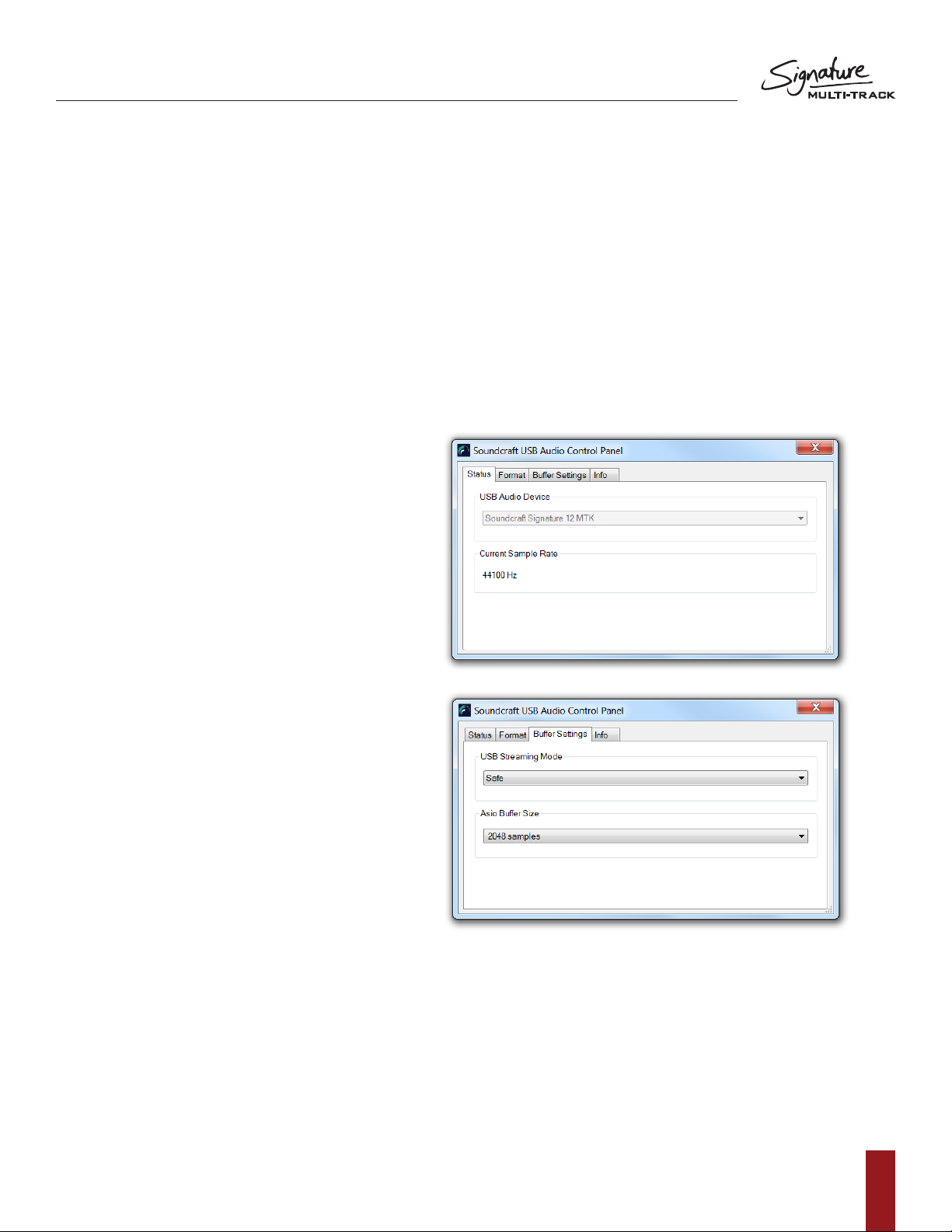
Navigating the Control Panel (PC Only)
The Soundcraft Audio Driver settings can be found
in the Soundcraft USB Control Panel. Within this
menu, there are options to adjust the streaming
mode of the Signature Series USB audio interface
and the buffer size from 64 samples up to 8192
samples. Recommended buffer size will vary
depending on application, however higher buffer
sizes should be used when monitoring from
the DAW is not necessary. For most recording
applications, a standard buffer size of 1024
samples is enough to ensure reliable operation and
clean audio.
The streaming mode settings modify the bahaviour
of the USB driver for maximum optimization when
set in conjunction with the buffer size setting. A
larger buffer size results in higher latency to your
DAW but provides a more robust audio stream to
your PC. A smaller buffer size reduces the latency
to your DAW but can result in audio glitches and
errors due to memory and CPU load on your PC.
To adjust the buffer size of the USB stream, both
the streaming mode and the buffer size settings
need to be set correctly corresponding to one
another.
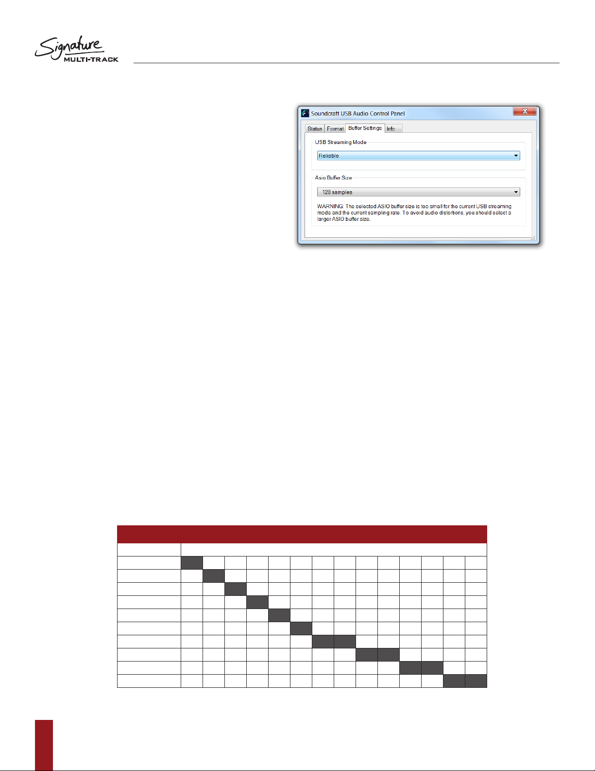
For example, setting the streaming mode to
‘Reliable’ and then the buffer size to 1024 samples,
the system will then be running at 1024 samples and the audio will be clean. For lower buffer sizes, the streaming
mode should be set to ‘Low Latency’ and the buffer size to 128 samples.
A mismatch between Streaming mode and buffer size could cause artefacts in the audio and could corrupt the
audio recording. A mismatched buffer setting such as setting the streaming mode to ‘Reliable’ and the buffer size
to 64 samples would result in distorted audio in your recording.
5
Page 6
SOUNDCRAFT SIGNATURE MTK RECORDING GUIDE
To avoid artefacts and to produce a reliable
recording you should select the appropriate
buffer size for the streaming mode. When a
mismatch occurs, a dialogue will appear at
the bottom of the control panel menu with
instructions of where to go from the current
setting to make a compatible setup.
USB Send and Return Channels
USB Send and Return channels are numbered according to console channel ledgering, so Signature 12MTK’s
input channels 1-12 for example are patched to USB audio channels 1-12 and Signature 22MTK’s input
channels are patched to USB audio channels 1-22.
Console channels always send their post-gain, pre-EQ signal to their respective USB channel to be picked up
and recorded by the PC/MAC Via USB. The 2-track (Master Left/Right) output uses the last 2 USB channels on
each console and is always actively sending post fader level down the USB stream.
Console channels can be set up to receive USB Input and can be engaged per-channel with the USB RTN
button located on each channel strip.
This means that channels that have been sent to the DAW for recording can then be returned from the DAW,
back through the console, converted to analogue and mixed as a standard input source. This makes things like
Virtual soundcheck and playback as easy as hitting the USB return button on the desired console channels.
Graphs 1 and 2 show the relationship between the input channels coming from the Mic pre, the USB Send
number and subsequently the USB return number for multichannel USB playback.
USB Send Channels (to DAW)
1 2 3 4 5 6 7 8 9 10 11 12 13 14
Channel 01 M / L
Channel 02 M / L
Channel 03 M / L
Channel 04 M / L
Channel 05 M / L
Channel 06 M / L
Channel 07/08 M / L L
Channel 09/10 M / L L
Channel 11/12 L L
Mix LR
GRAPH 1
6
Page 7

SOUNDCRAFT SIGNATURE MTK RECORDING GUIDE
M/L: Mic/Line
Input sources on the console are split into Mic and Line input sources. Channel 1 for example features an
XLR Mic and ¼” Jack line input and so the check box in Graph 1 is labeled M/L. On channel 9/10 however,
the channel strip features a Mic input and a set of stereo line input jacks (split into Left and Right). Mic and L/
Mono line input jack are connected to USB channel 9 but the other jack (input 10/Right) is sent down USB
channel 10. This needs to be taken into consideration when sending inputs to and from the DAW as a USB
send from USB out 9 will be received by the left side of channel 9/10 on the console and USB channel 10 will
send down the right side of the stereo channel.
Recording the LR
As you can also see in Graph 1, the USB channels 13 and 14 (23 and 24 on 22MTK) are reserved for the LR
stereo signal. This allows the user to record the nal mix on the console back into the DAW for an ‘audio mix
down’ or analogue summing purpose. The A/D conversion (the process of converting the analogue LR signal
to digital) takes place after the analogue summing of the input channel allowing for true analogue summing of
the input signals. The signal is sent POST-FADER to the USB and so adequate fader level must be achieved
in order to record a reasonable level for processing further.
Graph 2 displays the relationship between the input channels and their corresponding USB channel coming
into the console from the DAW. For example, to receive a USB input to channel 6 of the mixer, you must
assign the DAW track output to USB channel 6, switch the USB RTN switch ON for channel 6 and then you
will be receiving USB audio. Repeat across the console for Multi-track playback.
Channel 01
Channel 02
Channel 03
Channel 04
Channel 05
Channel 06
Channel 07/08
Channel 09/10
Channel 11/12
USB Send Channels (to DAW)
1 2 3 4 5 6 7 8 9 10 11 12
GRAPH 2
7
Page 8

SOUNDCRAFT SIGNATURE MTK RECORDING GUIDE
Stereo Playback
Stereo playback using PC
In order to use the USB port to play standard MP3’s or WAV les from your PC, there is a small amount of setup
required from the control panel in order to send the stereo le to the appropriate channel on the console.
On the Signature 12 and 22MTK respectively, channels 11/12 and 21/22 are stereo channels that are best suited
for stereo playback of things such as interval music or backing tracks from the PC. These channels are excluded
from the interval mute function and so will playback even when interval mute is engaged.
To assign stereo playback out of the desired USB channel:
1. Firstly enter the control panel and select ‘Hardware and Sound’
(Or just ‘sound’ depending on your view settings)
2. Select ‘Manage Audio Devices’
3. You will then be presented with a list of output options
a. From this list, you can select the output that corresponds with the desired playback channel
on the console. Ch 11/12 on Signature 12MTK and channel 21/22 on Signature 22MTK.
4. Finally you must enable the USB return option on the consoles playback channel
(or the channel number that has just setup).
NOTE: All system sounds will also play through the USB audio interface so caution must be
taken when navigating the operating system during a performance. These sounds can be
turned off in the sounds menu if desired.
8
Page 9

SOUNDCRAFT SIGNATURE MTK RECORDING GUIDE
Stereo playback using MAC:
To assign stereo playback out of USB
channels 11/12 (21/22 on 22MTK):
1. Firstly enter the ‘Audio MIDI setup’ control panel that
can be found by the Mac search bar or in the launch
pad > other folder.
2. When ‘Audio MIDI Setup’ has opened, you will notice
a ‘Soundcraft ‘x’-channel audio driver’ selection on
the left column.
3. To assign this device as the default output,
right click the selection and click ‘use this device
for sound output’.
4. You then need to set the output to USB
channels 11/12 (21/22 on 22MTK).
a. To do this, you need to right click the
‘Soundcraft ‘x’-channel audio driver’
andselect‘congurespeakers’.
b. From this dialogue, you can assign
a Left and Right output from the Mac
to playback through channels 11 and
12 respectively on the console
(21/22 on 22MTK).
5. Finally you must enable the USB return option
on the consoles playback channel (or the
channel number that has just setup).
NOTE: All system sounds will also play
through the USB audio interface so
caution must be taken when navigating
the operating system during a performance.
These sounds can be turned off in the
sounds menu if desired.
9
Page 10

SOUNDCRAFT SIGNATURE MTK RECORDING GUIDE
REAPER
®
Multi-track recording using REAPER
After the drivers have been installed on the PC and the console is connected to your chosen machine (PC or
MAC) we can begin to setup a project and start recording.
The following steps walk through DAW specic instructions for setting up the recording interface, patching inputs,
outputs, enabling record and adjusting sample rate settings from the DAW.
In this example, we will be covering REAPER however we will look into other DAWs in proceeding sections.
After you have installed REAPER following the detailed steps from the on screen procedure, you can then start
the program.
Once it has loaded, you will be presented with an empty project. Before tracks can be added and recording can
begin, you must rst assign REAPER to use the Soundcraft Multichannel audio interface.
1. Firstly, go into the options tab at the top of the
screen and scroll down to preferences.
2. On the left menu, scroll down to device under
the ‘audio’ heading.
3. Select the ‘Audio system’ drop down
and select ASIO
a. If you have more than one ASIO
driver installed on your machine,
ensure that Soundcraft USB Audio
ASIO is selected on the ‘ASIO Driver’
drop down menu.
4. Select the desired range of inputs and outputs
under the appropriate drop down menus.
a. For maximum record and playback
facilities on the Soundcraft Signature 12,
engage inputs Analogue 1 - Analogue 14
and outputs Analogue 1 - Analogue 12.
b. Signature 22MTK will require a larger
range of inputs such as
Analogue 1- Analogue 24 and
outputs Analogue 1 – Analogue 22.
5. Check the request sample rate box and enter
your desired sample rate.
a. 44.1 kHz recording should be entered
as 44100 and 48 kHz recording should
be entered as 48000.
NOTE: higher sample rates are not
compatible with the Signature series
Multi-track consoles.
10
Page 11

SOUNDCRAFT SIGNATURE MTK RECORDING GUIDE
6. Close the REAPER preferences screen and return
to the blank project.
7. Go into ‘insert’ at the top of the screen and select
multiple tracks
8. Enter your desired amount of record tracks in the
insert how many tracks box. The maximum is 14 for
the Signature 12MTK so for this example we will
insert 14 tracks.
a. The maximum recording
channels on the 22MTK is 24, so to
record all available input signals,
add 24 tracks into REAPER.
9. Next we must assign the channels within REAPER to
receive signals incoming via USB FROM the console into
the appropriate tracks in REAPER. Go into View at the top
of the screen and open up the Routing Matrix.
a. You will be presented with a Matrix
that has Sources down the left column
and destinations across the top.
b. In order to patch 1:1 the console
USB sends and REAPER channels
we must engage the connection
between the source and destination.
c. Engaging a connection is done simply
by clicking in the appropriate box in the grid.
10. Scroll across the top through all of the track names and
assign the patches to the desired analogue input.
a. Track 1 to Analogue 1, Track 2 to analogue 2,
Track 3 to analogue 3...
b. When a patch is made you will see a red circle
appear in the desired patch.
c. You will end up with a diagonal line running from
track 1 input 1 to track 14 input 14.
(Track 24 to input 24 on signature 22MTK)
d. After all the patches have been made,
exit out of the routing matrix.
11. Open up the mixer view from the View tab by entering
View at the top of the screen and selecting Mixer.
(It may already be open at the bottom of the screen).
12. Record enable all of your input tracks by engaging the
record arm key on each channel fader.
13. At this point, if any input sources are coming into the
desk, you will see the channel meters on REAPER
begin to show level.
11
Page 12

SOUNDCRAFT SIGNATURE MTK RECORDING GUIDE
14. When you are ready to record the show, select the master record button by the transport control to begin
recording! You will see waveforms starting to appear in the transport window indicating tracks are being
recorded and audio is being written to the hard disk.
15. Onceyouhavenishedrecording,simplypressthespacebaronyourkeyboardorpresstheSTOPkeyon
REAPER’s transport section. You will then be prompted with a dialogue requesting an action with your recently
recordedaudioles.PressSAVEALLifyouwishtokeeptheaudioorDELETEALLifyouwishtotryagain.
TIP: You can always delete unnecessary audio; you can’t make it up the event! We always suggest you
keep all takes and audio les until after everything can be reviewed in a different location with a fresh pair
of ears. You may have missed the magic take!
Multichannel playback using REAPER
®
Once your project has been created and tracks have been recorded, you can then follow a few more
steps to playback the channels from the DAW back through the console. To do this, we must assign the
outputs of each channel to the corresponding USB output. In REAPER, this can be done via the convenient
routing matrix screen.
1. Firstly, open up the routing matrix via the ‘view’ menu at the top
of the screen.
2. Along the top of the grid you can see the possible destinations
(USB Outputs) and down the left of the grid you can see the
input channels laid out consecutively.
a.Wemustrstunassignthemasteroutputbydeselecting
the patch that is made by default connecting master
output to ‘Analogue 1’ (stereo).
3. Next,ndchannel1onthelefthandcolumnandfollowacross
the rows until you can see ‘analogue output 1’. Connect this
patch by clicking on the grid in the resulting box.
a. Then we must repeat the same steps for
channel 2 by connecting channel 2 to ‘analogue output 2’.
b. When all of the channels are patched, you will be left
with a diagonal line of patches indicating that the
channels within the DAW are patched to their
respective USB outputs.
12
4. Moving back to the console, next we must engage the USB RTN switch located
below the input gain control on the console channels.
a. Once switched, the console channels are ready to receive audio via USB.
5. BeforepressingplayonREAPER,youmustrstdeactivatetherecordenableswitches
located in the DAW channel strips.
a. This is for safety to avoid recording over your recorded show and also to avoid any
chance of feedback loops occurring etc.
6. Once the above steps are complete, you can press play on the transport controls within REAPER
and begin mixing the USB signals with the powerful mixing capabilities of the console.
Page 13

SOUNDCRAFT SIGNATURE MTK RECORDING GUIDE
Inserting plug-ins on REAPER
Once the project has been created and the tracks have been setup to send and receive out of the corresponding
USB channels of the mixer, you are able to follow a few extra steps in order to use plug-ins inserted into the input
channels. On REAPER, the process is quick and easy.
1. Once your tracks are setup to receive and send out of the corresponding USB channels, you then need to enable
monitoring on each channel.
a. This allows the audio to pass through the audio tracks’ channel strip and
back out of the USB channel.
2. On each audio channel you need to select the small speaker icon beneath
the solo button on each track.
a. Engaging this button allows for Input record monitoring. You will not notice any audio
going through the channel strip until you follow the next step.
3. Finally, on each audio track you need to engage the ‘record enable’ button in
order for the audio to pass through the input channels.
a. After engaging this button on each track, you should notice an input
meter on channel begin to show level.
4. You can now click on the rectangular insert points above the fader and the ‘outputs/sends’ section to select your
desired plug in insert and effect the input channel. You can use the DAW fader as a ‘return level’ back into your
console if you need to make any adjustments to the gain structure.
LOGIC
Multi-track recording using LOGIC 9.1.8
Once LOGIC has loaded, you will be presented the LOGIC
toolbar at the top of the screen. Before tracks can be added
and recording can begin, you must rst create a new project.
1. Go into the ‘File’ menu at the top of the screen
and select the New option.
a. You will then be presented with a dialogue
to select the preferred new project
template based on preference.
b. We suggest using an Empty project.
2. Once the project has loaded up, you may be prompted to
add an audio track. For now, select Create to add a track
and get the project started. We will delete this track later.
3. Now we must assign our desired audio interface into
LOGIC. To do this, select the ‘preferences’ icon located on
the top toolbar of logic and select Audio.
13
Page 14

SOUNDCRAFT SIGNATURE MTK RECORDING GUIDE
4. Select the output device drop-down and scroll
down to select ‘Soundcraft Signature 12 MTK’
(22 MTK if you are using the larger model).
a. Once the output device has been selected,
you can then do the same for the Input
device drop-down.
b. Once both the input and output device has
been set to the ‘Soundcraft Signature
12MTK’, press ‘Apply Settings’ and can
exit this dialogue and return to the blank
project arrange screen.
5. Next, enter the Settings tab located in Logic’s
toolbar section and select the sub heading Audio.
a. From here, it is possible to select your
desired project sample rate under the
‘Sample rate’ drop-down menu.
b. On a Signature MTK console there will only
be options for either 44.1kHz or 48kHz.
c. Select your desired sample rate and exit
the Settings tab returning to the
arrange page with your blank project.
NOTE: higher sample rates are not
compatible with the Signature series Multitrack consoles.
6. Now it is time to add the audio tracks for
recording. Above the temporary audio track we
created earlier, there is a small ‘+’ icon. Select this
button and you will be presented with the
‘new tracks’ menu screen.
a. In the ‘number’ dialogue, we need to type
in our desired number of recording
channels. For this example, we’ll type in 14.
b. Make sure that the format is set to ‘mono’
and the Input is set to ‘input 1’. Select
the ‘ascending’ box to ensure Logic creates
consecutive input patches for the
following channels.
c. Next, we must assign the output range.
Select the output drop down box, hold the
cursor over output, then over mono and
nally,selectoutput1.
d. Select the ‘ascending’ box by the output
drop down to ensure Logic creates
consecutive output patches for the
following channels.
e. Finally, we must select ‘record enable’ on
thenalcheckboxtoautomatically
record enable all of the DAW tracks.
f. After the above steps have been followed,
you can then select ‘Create’ to add
these tracks into the project.
14
NOTE: If any input sources are coming
into the desk at this point, you will see
the channel meters on LOGIC begin to
indicate level.
Page 15

SOUNDCRAFT SIGNATURE MTK RECORDING GUIDE
7. When you are ready to record the show, select
the master record button by the transport
control section to begin recording! You will see
waveforms starting to appear in the transport
window indicating tracks are being recorded and
audio is being written to the hard disk.
8. Onceyouhavenishedrecording,simplypress
the space bar on your keyboard or press the
STOP key on LOGIC’s transport section.
Multichannel playback using Logic
Once your project has been created and tracks have been recorded, you can then follow a few more steps to
playback the channels from the DAW back through the console for an analogue style mixing session.
To do this, you must assign the outputs of each channel to the corresponding USB channel of the console.
If you followed all of the above steps from the previous procedure, you will already be setup and ready for
playback through the console.
If you DID follow the steps above:
All that is required by the user is to disable the record enable icon on each DAW track, enable the USB RTN
switch on the console channels and to press play on the DAW’s transport controls.
If you did NOT follow the steps above:
You can follow the below steps to patch the DAW channels to the correct USB outputs following steps:
1. Open up the Mixer view by pressing either ‘COMMAND+2’ on the keyboard or via the
view tab at the top of the screen.
a. You will then be presented with the Mixer interface; All of the DAW channels are laid
out from left to right and above each channel fader and pan control there are 2 dialogue
boxes that contain the input and output patch of each channel.
2. Click and Hold the bottom of the two I/O boxes to open up the output selection pop up.
3. Scroll down to outputs, mono and select output 1
(Ortherst‘partofstereo‘dialogue).
4. Then assign the next tracks output to be mono
output 2. Repeat across all recorded channel
either to assign the Daw outputs to the mixers
USB interface.
5. Once all of the tracks have been patched to their
respective outputs, you then need to disable
record enable on each input tracks and then press
play on Logic’s transport bar.
15
Page 16

SOUNDCRAFT SIGNATURE MTK RECORDING GUIDE
Inserting plug-ins on LOGIC
Once the project has been created and the tracks have been setup to send and receive out of the corresponding
USB channels of the mixer, you are able to follow a few extra steps in order to use plug-ins inserted into the input
channels. On Logic, the process is quick and easy.
1. Select the ‘preferences’ icon located on the top toolbar of logic and select Audio.
2. Check the box that is labeled ‘software monitoring’.
a. This setting allows audio to pass through the DAW from input to output and will allow the DAW
channel to be inserted into the mixer.
3. The next setting we need to adjust is the Buffer Size located in the drop down menu.
a. In order to achieve minimal latency, we must engage the lowest buffer setting possible.
We recommend a buffer size of 64 or 128 samples to retain reliability and achieve lowest latency.
Note: Buffer size determines the amount of latency you will hear in and out of your DAW. When you
are recording, you should set the buffer size to a lower amount to reduce the amount of latency for
more accurate monitoring. The downside to lowering the buffer size is that it puts more pressure
on your computer’s processors and forces them to work harder. The lowest buffer size that can
be achieved is dependent on the performance of your computer and the amount of processing
employed in your DAW.
b. Once the buffer size has been set, press Apply and close the dialogue.
4. Next, select record enable on all of the input channels, at this point you should notice
the meters begin to show level.
5. Engage USB RTN on the console for all of the input channels you wish to insert plug-ins, you should
now notice signal being returned back into the console via the DAW.
6. The signal path is now being sent post gain, through the DAW and back into the console for
further processing. You are now able to insert plug-ins into the incoming channels for
extra processing via LOGIC.
a. LOGIC has another setting for even lower latency when monitoring through the DAW.
This setting disables all high power plug-ins that may be active and be causing extreme
latency to achieve the lowest possible delay from input to output. To enable this setting, right
click the logic transport bar and check the box that allows for Ultra-low latency operation. This
setting can then be enabled/disabled from the transport panel using the ‘speedo’ icon.
16
Page 17

SOUNDCRAFT SIGNATURE MTK RECORDING GUIDE
ABLETON LIVE LITE
Stereo recording using ABLETON LIVE LITE
After the drivers have been installed on the PC and the
console is connected to your chosen machine (PC or
MAC) we can begin to setup a project and start recording!
The following steps walk through DAW specic
instructions for setting up the recording interface,
patching inputs, outputs, enabling record and adjusting
sample rate settings from the DAW.
In this example, we will be covering ABLETON LIVE
LITE, however the setup also covers ABLETON LIVE and
ABLETON SUITE. After you have installed ABLETON LIVE
LITE and followed the detailed steps during the install
procedure, start ABLETON LIVE LITE.
Once it has loaded, you will be presented with an empty
project (or your previously loaded project depending on
your settings). Before tracks can be added and recording
can begin, you must rst assign ABLETON LIVE LITE to
use the Soundcraft Multichannel audio interface.
1. First, you must open up the preferences menu –
On a Mac this is under the ‘live’ tab at the top of
the screen.
a. From here you will need to assign an ‘Audio
Input Device’ As well as an ‘Audio
Output Device’. Select the drop down
menus and select the Soundcraft Digital
option under each drop-down.
b. Once the audio driver is selected, you will
then see the options for sample rate, and
buffer sizes appear below. Beneath ‘Audio
Output Device’, you will see an option for
‘InputCong’and‘OutputCong’.
c.Select‘InputCong’andengagethecorrect
stereo pair for the console you have
(11/12 or 21/22). You can then select ‘Output
cong’andassigntheUSBreturntooneof
the available USB outputs. Setting these
channels to the corresponding Stereo return
channels on the mixer would mean that you
canplaybackyourrecordedleswitha
simple button press on the consoles
USB return.
17
Page 18

SOUNDCRAFT SIGNATURE MTK RECORDING GUIDE
d. Once these are selected, you can close
the window and return to the arrange page.
Note: For familiarity with other DAWs, consider
using the “Arrangement View” of ABLETON
LIVE LITE over the “Session View” using the
view type in the top right of the screen.
e. Once you are in the arrange page, you
can then assign an audio track to receive
audio from the console. This can be done
using the drop down located in the
audio track.
f. Turn on input monitoring by engaging the
IN beneath the input selection drop down.
After doing this, you will then notice input
signal appearing on the track meter.
g.Thennally,recordenablethetrackby
engaging the record arm button and then
select Record on the top navigation bar to
begin recording the audio; you will see a
waveform appear on arrange page when the
audio is recording correctly and the inputs are
setup. Finally, press the record button on the
navigation bar again to stop the recording
process.
18
Page 19

SOUNDCRAFT SIGNATURE MTK RECORDING GUIDE
Inserting plug-ins on ABLETON LIVE LITE
Once the project has been created and the tracks have been setup to send and receive out of the
corresponding USB channels of the mixer, you are able to follow a few extra steps in order to use
plug-ins inserted into the input channels. On ABLETON LIVE LITE, the process is quick and easy.
1. Once your tracks are setup to receive and send out of the corresponding USB channels,
you then need to enable monitoring on each channel.
a. This allows the audio to pass through the audio tracks’ channel strip and
back out of the USB channel.
2. On each audio channel you need to select ON which is located just beneath
the input source selection.
a. After engaging this button on each track, you should notice an input meter on
channel begin to show level.
3. You can now click on ‘Audio effects’ on the left hand side column and begin to drag and drop
Audio effects into the track space at the bottom of the arrange page.
a. Once a plug in is dropped into position, the audio will begin to be affected by
the selected plug in. You can use the DAW fader as a ‘return level’ back into your
console if you need to make any adjustments to the gain structure.
19
Page 20

www.soundcraft.com
Cranborne House, Cranborne Road, Potters Bar, Hertfordshire EN6 3JN, UK
T: +44 (0)1707 665000 F: +44 (0)1707 660742 E: soundcraft@harman.com
Soundcraft USA, 8500 Balboa Boulevard, Northridge, CA 91329, USA
T: +1-818-893-8411 F: +1-818-920-3208 E: soundcraft-usa@harman.com
Soundcraft, Harman International Industries Ltd.,
 Loading...