

Page 1

Featuring
Page 2

Page 3
INTRODUCTION
Thank you for purchasing a Monitor 2 mixer, brought to you with pride by the SPIRIT team of Andy, Colin,
Chris, James, Simon, Mukesh, Graham, Martin, Paul, Tony and Peter, with the support of many others - we
hope you will have as much fun using it as we did building it!
SAFETY PRECAUTIONS
For your own safety and to
avoid invalidation of the
warranty please
read this section carefully.
The SPIRIT MONITOR 2 mixer must only be connected
through the Power Supply supplied.
The wires in the mains lead are coloured in accordance with the
following code:
Earth: Green and Yellow
(Green/Yellow - US)
Neutral: Blue
(White - US)
Live: Brown
(Black - US)
As the colours of the wires in the mains lead may not correspond
with the coloured markings identifying the terminals in your plug,
proceed as follows:
l The wire which is coloured Green and Yellow must be
connected to the terminal in the plug which is marked with
the letter E or by the earth symbol.
l The wire which is coloured Blue must be connected to the
terminal in the plug which is marked with the letter N.
l The wire which is coloured Brown must be connected to the
terminal in the plug which is marked with the letter L.
Ensure that these colour codings are followed carefully in the
event of the plug being changed.
To avoid the risk of fire, replace the mains fuse only with
the correct value fuse, as marked on the rear panel.
Page 2
Page 4
Connecting Up
24
INPUTS
Page 3
Page 5
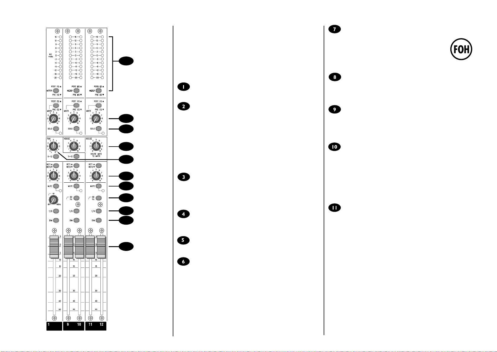
USING MONITOR 2
1
5
2
3
4
6
7
Mono Input Channel
XLR Input
The UltraMic Plus padless input preamp is designed to accept BALANCED or
UNBALANCED signals at a wide range of input levels up to +28dBu. When
using microphones, professional dynamic, condenser or ribbon mics are best
because these will be LOW IMPEDANCE. You can use low-cost HIGH
IMPEDANCE mics, but the level of background noise will be higher. If you
press the 48V switch down the socket provides a suitable powering voltage
for professional condenser mics (this is also known as Phantom Power).
Each input is provided with a male XLR-type SPLIT OUT connector, which
enables mic signals to be fed directly to a Front-of-House mixer without the
need for specials cables or splitter boxes. Always provide 48V powering
from the Monitor 2 console if required, and turn off the powering at the
FOH console.
An internal jumper option is provided to allow the ground connection to the
SPLIT OUT connector to be lifted to prevent ground loops in certain
installations.
ONLY connect condenser microphones with the 48V
powering OFF (switch UP), and ONLY turn the 48V
powering on or off with all output faders DOWN, to
prevent damage to the mixer or external devices. If the
SPLIT OUT connectors are used to feed another mixer,
the MONITOR 2 console should be powered up first, or
the faders on the FOH console should all be down when
the MONITOR 2 is powered up or split feeds connected.
DO NOT turn on the +48V when using unbalanced sources
or line level signals, which may be damaged by the phantom
power voltage on pins 2 & 3 of the XLR connector, and
ONLY connect the SPLIT OUT feed to inputs which can
tolerate phantom power voltages if the powering is in use.
100Hz HI-PASS FILTER
Pressing this switch activates a steep 18dB per octave filter which reduces
the level of bass frequencies only. Use this in live PA situations to clean up
the mix, reducing stage rumble or popping from microphones.
INSERT POINT
The unbalanced, pre-EQ insert point is a break in the channel signal path,
allowing limiters, compressors, special EQ or other signal processing units to
be added in the signal path. The Insert is a 3-pole A gauge jack socket which
is normally bypassed. When a jack is inserted, the signal path is broken, just
before the EQ section. The Send may be tapped off as a line level, pre-fade,
pre-EQ send of a mic source if required, using a lead with tip and ring
shorted together so that the signal path is not interrupted.
EQUALISER
Powerful, corrective Equalisation (EQ) is essential in live situations to cope
with varying venue acoustics and original signals which may be far from ideal.
Each Monitor 2 input is provided with a comprehensive 4-Band EQ section,
with two swept mids for extra control.
HF EQ
Turn clockwise to boost high (treble) frequencies (12kHz and above) by up
to 15dB, adding crispness to cymbals, vocals and electronic instruments.
Turn anticlockwise to cut by up to 15dB, reducing hiss or excessive sibilance
which can occur with certain types of microphone. Set the knob in the
centre-detented position when not required.
MID EQ (HMID & LMID)
There are two pairs of knobs which work together to form HI and LO MID
frequency EQ sections. The lower knob in each pair provides 15dB of boost
and cut, just like the HF EQ knob, but the frequency at which this occurs can
be set by the upper knob over a range of 550Hz to 13kHz (HMID) or 80Hz
to 1.9kHz (LMID). This allows some truly creative improvement of the
signal in live situations, because the mid bands cover the range of most
vocals. Listen carefully as you use these controls together to find how
particular characteristics of, for instance, a vocal signal can be enhanced or
reduced. Set the gain (lower) knob to the centre-detented position when
not required. Note: Q is set at 1.5.
LF EQ
PHASE REVERSE
Pressing this switch reverses the polarity of the input, providing a
convenient method of compensating for incorrect wiring or microphone
placement. In some circumstances it may be found that pressing PHASE
REVERSE will help with feedback avoidance. The switch should normally
be released when not required. Note that the SPLIT OUT feed is NOT
affected by this switch.
SENS (Sensitivity)
This knob sets how much of the source signal is sent to the rest of the
8
mixer. Too high, and the signal will distort as it overloads the channel. Too
low, and the level of any background hiss will be more noticeable and you
may not be able to get enough signal level to the output of the mixer.
Setting the knob to the `0 mark gives unity gain for line level signals. See
`Setting Up & Troubleshooting on page 8 to learn how to set SENS
correctly.
Page 4
Turn clockwise to boost low (bass) frequencies (60Hz and below) by up to
15dB, adding warmth to vocals or extra punch to synths, guitars and drums.
Turn anticlockwise to cut low frequencies by up to 15dB for reducing hum,
stage rumble or to improve a mushy sound. Set the knob to the centredetented position when not required.
EQ SWITCH
The EQ switch bypasses the Equalisation section when released. Alternately
pressing and releasing the switch provides an easy way of comparing the
equalised and unequalised signals.
Page 6
MONITOR SENDS
7
9
10
12
11
8
These controls route the input channel signal to any one or more Monitor
busses and the associated Monitor Outputs, allowing a number of unique
monitor mixes to be created. The sends are arranged as a group of mono
sends (1-8) and two stereo pairs (9/10 & 11/12). Each group of sends is
normally POST-FADE, POST-EQ but may be switched to PRE-FADE,
POST-EQ by pressing the corresponding PRE switch. All sends are muted
when the MUTE switch (9) is pressed. Sends 9-12 are arranged as two
stereo pairs, with a send level control and a PAN control to position the
channel signal in the stereo image. With the PAN control centered, the
signal is fed equally to both sends in the pair. You get most control when the
input Sensitivity is set up correctly, giving maximum travel on the send
controls. See the `Setting Up & Troubleshooting section on page 8 for help
in setting a suitable signal level.
MUTE
All monitor sends are disabled when the MUTE switch is down, and the
associated amber LED illuminates to show that the switch is pressed.
FADER
The FADER provides overall level control of any Monitor Sends which are
selected as post-fade. You get most control when the input Sensitivity is set
up correctly, giving full travel on the fader. See the `Setting Up &
Troubleshooting section on page 8 for help in setting a suitable signal level.
SIGNAL LED
This green LED illuminates to show that a signal with a level greater than
-20dB is present in the channel.
PFL/PEAK
When the latching PFL switch is pressed, the pre-fade, post-EQ signal is fed
to the headphones and engineers wedge outputs, replacing the selected
wedge source and illuminating the SOLO/PFL LED on the Master section to
show that a PFL is active. The adjacent red LED lights to identify the
selected channel. This is a useful way of listening to any required input
signal without interrupting any of the monitor sends, for making
adjustments or tracing problems.
When the PFL switch is released the LED serves as a PEAK indicator which
illuminates approximately 4dB before clipping to give warning of a possible
overload. The signal is sampled at two points in the EQ section and at the
Insert Send.
Page 5
Page 7
11
10
OUTPUT SECTION
MONITOR OUTPUTS
These outputs provide summing of the corresponding input channel
monitor sends, and drive XLR-type output sockets from impedance
balanced outputs. A break-point is included before each output socket for
the connection of an external graphic equaliser.
Outputs 1-8 are configured as mono sends, and outputs 9/10 and 11/12 are
arranged as stereo pairs.
MUTE
The monitor send is completely disabled when the MUTE switch is pressed,
and the adjacent LED illuminates to warn that the mute is active.
HIGH PASS FILTER (1-8 only)
9
8
7
6
1
2
3
4
5
A variable High Pass Filter is provided to reduce the level of stage-driven
low frequency feedback, or particularly to tailor the output frequency to
match the frequency range of smaller wedge monitor speakers which may
not be able to tolerate high levels of LF signal. Rotate the control fully
anticlockwise when the filter is not required.
60Hz Filter (9-12 only)
A fixed 60Hz high-pass filter is provided on outputs 9/10 and 11/12, which
might typically be used for in-ear monitor transmitters, effects sends or
FOH PA. The filter helps to clean up the mix and reduce large low
frequency transients.
T/B
Pressing the T/B (Talkback) switch routes the talkback mic signal to the
monitor output and simultaneously dims the monitor signal to allow the
engineers voice to be heard over the mix. The Talkback level is set by the
T/B SENS control on the Master section. Talkback is disabled when the
DIM switch is pressed.
DIM
Pressing the DIM switch attenuates the monitor output by 6dB as an
immediate way of eliminating feedback while the source of the problem is
identified.
FADER
The 100mm fader controls the overall level of each output. The 0 mark
gives unity gain from the fader, leaving 5dB in hand.
FX RETURNS
The signal from either of the two stereo FX Returns may be mixed directly
to the Monitor output at a level set by the local control (overall level is set
by the FX1 RET and FX2 RET controls on the Master section). The
RET1/RET2 switch selects FX Return 1 when released, and FX Return 2
when pressed. On outputs 1-8 the FX Return signal will be a mono sum of
left and right, and on 9-10 and 11-12 the signal will be fed in stereo. Note
that FX Return 1 may be globally switched from the Master section to be
the House Mic signal if required.
FOH Facility
A sub-grouping facility is included on outputs 1-10 to allow the
console to be used as a FOH mixer. Pressing the 11-12 switch
routes the post-fade, post-insert signal to the Monitor 11/12
busses, enabling these outputs to be used as a stereo final mix.
The PAN control positions the monitor signal in the stereo
image (outputs 1-8 only). Final mix level is controlled by the
11-12 Monitor Fader.
HOUSE
On the stereo output pairs (9/10 and 11/12) the HOUSE control injects an
ambience signal picked up from the stereo House Mic inputs into the
monitor outputs, which is particularly important when feeding in-ear
monitors.
MNTR (Monitor - Engineers Wedge)
A separate monitor mix may be created for the Engineers Wedge monitor
or Headphones. The POST EQ/PRE EQ switch selects the source for the
mix as before or after the Graphic EQ insert point, and will normally be
post-EQ (switch released). Rotate the MNTR control fully anticlockwise
when not required.
SOLO
When the latching SOLO switch is pressed, the post- or pre-Graphic EQ
signal (as selected by the POST EQ/PRE EQ switch) is fed to the
headphones and engineers wedge outputs, replacing the selected wedge
source and illuminating the SOLO/PFL LED on the Master section. The
adjacent red LED lights to identify the active solo. This is a useful way of
listening to any required output signal without interrupting any of the
monitor sends, for making adjustments or tracing problems. In the case of
outputs 1-8 the SOLO signal will be mono to left and right, while 9/10 and
11/12 are fed as stereo.
BARGRAPH METERS
3-colour peak reading BARGRAPH METERS are provided to monitor the
final output, giving you a constant warning of excessive peaks in the signal
which might cause overloading. Aim to keep the signal within the amber
segments at peak levels for best performance. Similarly, if the output level
is too low and hardly registering at all on the meters, the level of
background noise may become significant. Take care to set up the input
levels for best performance.
The source for the meter may be selected as PRE or POST the Graphic EQ
insert point, as set by the adjacent METER switch. With the switch released
the meter will be fed from the POST-EQ signal.
Page 6
Page 8

10
MASTER SECTION
WEDGE SOURCE
The Engineers Wedge outputs are normally fed from a mix of the MNTR
2
4
5
1
6
7
8
9
feeds from outputs 1-12. The pre-fade wedge signal feeds the headphones
and meters and the post-fade signal feeds the XLR outputs.
Pressing the WEDGE SOURCE switch selects monitor outputs 11-12 as the
source for the wedge outputs, and would be used to monitor those outputs
when the mixer is used as a FOH console with outputs 1-10 submixing to
11-12.
When any PFL or SOLO switch is pressed the source for the Wedges is
switched to the PFL/SOLO signal without interrupting the other outputs
from the mixer, to allow individual signals to be monitored. The original
wedge source is restored when the PFL/SOLO switches are released.
BARGRAPH METERS
3-colour peak reading BARGRAPH METERS are provided to monitor the
wedge outputs, giving you a constant warning of excessive peaks in the
signal which might cause overloading. Aim to keep the signal within the
amber segments at peak levels for best performance. Similarly, if the output
level is too low and hardly registering at all on the meters, the level of
background noise may become significant. Take care to set up the input
levels for best performance.
The source for the meter is selected by the WEDGE SOURCE switch (see
above).
FADER
The 100mm fader controls the overall level of the wedges output. The 0
mark gives unity gain from the fader, leaving 5dB in hand.
PHONES
This control sets the level to the PHONES jack. The source for the Phones
is selected by the WEDGE SOURCE switch.
When any PFL or SOLO switch is pressed the source for the Headphones
is switched to the PFL/SOLO signal without interrupting the other outputs
from the mixer, to allow individual signals to be monitored. The original
phones source is restored when the PFL/SOLO switches are released.
FX RETURNS
Two balanced Stereo Returns are included for the outputs of effects units
and are made available for mixing directly to the Monitor outputs at a level
set by the FX1 RET or FX2 RET controls. If a mono source is used, plugging
into the Left jack only automatically feeds the signal to both Left and Right.
Pressing the HOUSE switch replaces the FX Return 1 signal with the House
Mics signal (at a level set by the HOUSE SENS control), to allow the House
Mics signal to be fed to any of the monitor outputs. Note that the House
Mics signal can be injected directly into outputs 9/10 and 11/12 without
using this facility.
T/B SENS
A balanced XLR input is provided for a local talkback microphone, and this
controls sets the level that this mic signal is fed to the selected monitor
outputs.
MASTER T/B
Pressing this switch routes the Talkback signal to ALL monitor outputs and
simultaneously dims the monitor signals to allow the engineers voice to be
heard over the mix. The Talkback level is set by the T/B SENS control.
Talkback is disabled when the Master DIM switch is pressed.
MASTER DIM
Pressing the DIM switch attenuates ALL monitor outputs and the wedges
output by 6dB as an immediate way of eliminating feedback while the
source of the problem is identified. The previous level is restored when the
switch is released.
LAMP CONNECTOR (not illustrated)
Two 4-pin XLR-type connectors are fitted at either end of the console for
the mounting of 12V gooseneck lamps (Littlite or similar).
The connector pinout is as follows:
Pin 1 - 12V AC (1)
Pin 2 - No connection
Pin 3 - 12V AC (1)
Pin 4 - 12V AC (2)
SOLO/PFL TRIM
3
The TRIM control provides +/-15dB level adjustment of the SOLO/PFL
signal to allow for differences in operating levels. Note that the position of
this control does not affect the level to the meters.
HOUSE MICS
Two balanced XLR inputs are provided for House Mics, and the HOUSE
SENS control sets the input level.
Pressing +48V switches on the powering voltage for condenser
microphones if required.
ONLY connect condenser microphones with the 48V
powering OFF (switch UP), and ONLY turn the 48V
powering on or off with all output faders DOWN, to
prevent damage to the mixer or external devices.
Page 7
Page 9

Setting Up & Troubleshooting
Initial Set Up
Once you have connected up your system (see the
sections on connection and wiring earlier in this manual
for guidance) you are ready to set initial positions for
the controls on your mixer.
The front panel drawing on page 17 shows typical
initial control positions which may serve as a
useful guide to setting up the mixer for the first
time.
Set up individual input channel as follows:
l Connect your sources (microphone, keyboard
etc.) to the required inputs. Note: Phantom
powered mics should be connected before the
48V is switched on.
The input provides very wide gain range without
the need for a pad. When using LINE level
sources, set the INPUT SENS control fully
anticlockwise as a preliminary position.
l Set Monitor faders at 0, input faders at 0, and set
power amplifier levels to suit the application.
Make sure that the EQ switches are released to
bypass the EQ sections.
l Provide a typical performance level signal and
press the PFL button on the first channel,
monitoring the level on the L/R bargraph meters.
l Adjust the input sensitivity until the meter display
is in the amber section, with occasional peaks to
the first red LED at a typical maximum source
level. This allows sufficient headroom to
accommodate peaks and establishes the
maximum level for normal operation (but see
note below).
l Feed the signal to selected monitor outputs by
setting the appropriate monitor sends to an initial
working level (approx. position 7 on the send
knob). Listen to the signal by feeding the
selected monitor signal to the engineers wedge
by turning up the MNTR control on the
appropriate outputs, checking that the wedge
source is selected to MNTR.
l Repeat this procedure on other channels as
required. As more channels are added to the
mix, the meters may move into the red section.
Adjust the overall level using the Monitor Output
faders if necessary.
l Listen carefully for the characteristic sound of
`feedback. If you cannot achieve satisfactory
input level setting without feedback, check
microphone and speaker placement and repeat
the exercise. If feedback persists, it may be
necessary to use a Graphic Equaliser to reduce
the system response at particular resonant
frequencies.
Note: The initial settings should only be regarded as a
starting point for your mix. It is important to remember
that many factors affect the sound during a live
performance, for instance the channel EQ settings or even
the size of the audience!
Each monitor mix can now be built up progressively,
listening carefully for each component in the mix and
watching the meters for any hint of overload. If this
occurs, back off the appropriate Input Fader slightly
until the level is out of the red segments, or adjust the
Monitor Faders.
Troubleshooting
No Power
l Is the mains supply present? Check the mains
outlet with another device.
l Is the power lead firmly connected?
Condenser Mic Not Working
l Is the 48V turned on?
l Is there an unbalanced device connected to the
SPLIT OUT connector?
l Is the mic cable a balanced 3-wire type?
Meters not showing any signal
l Has the input gain been set correctly (see
above)?
l Are the Monitor faders set at a working level.,
and are input faders set high enough?
l Is the MUTE switch released on the relevant
channels?
l If monitoring on the wedge outputs, is the
appropriate Monitor output feeding the wedges
(MNTR control set to working level), and the
wedge source selected to MNTR?
l Is there a PFL/AFL pressed on another channel?
No Monitor output, or output low level
l Is the MUTE switch released?
l Is a Graphic EQ or other external device
connected to the graphic Insert, and is this
device switched on and set up correctly?
l Are the local or Master DIM or T/B switches
released?
Headphones Distorting
l Are the headphones less than 200W impedance?
l Is the Phones level set too high?
Hum on outputs when SPLIT OUT sockets are used
l Check for ground loops, and try isolating the
SPLIT OUT ground connection by removing the
internal jumper which is normally fitted (see
below).
RB3831
REV
JMP1
SPLIT OUTPUT
PIN 1 GROUNDING
LINK - GROUNDED
NO LINK - GROUND LIFT
SPIRIT MO
SPIRIT B
Page 8
Page 10

APPLICATIONS
Live Monitor with Effects
BAND INSTRUMENTS/VOCALS
Page 9
Page 11
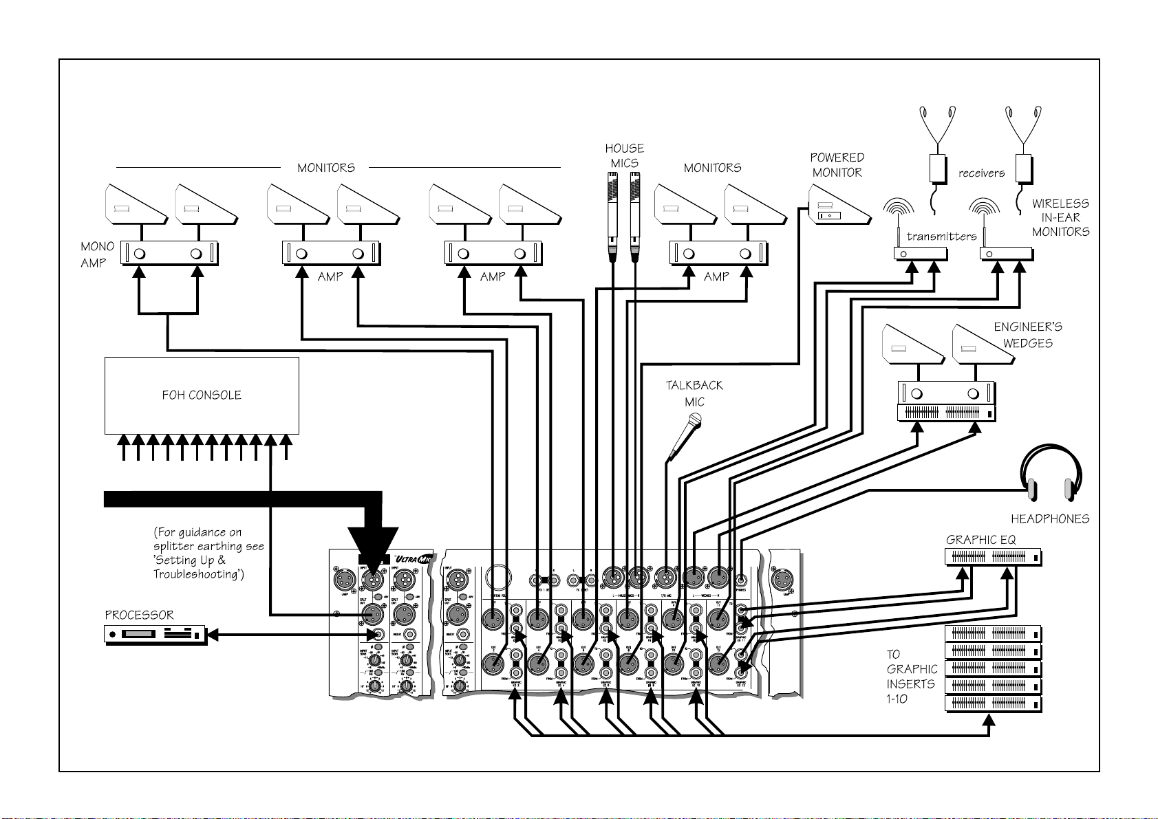
Live Monitor with In-Ear Monitoring
BAND INSTRUMENTS/VOCALS
Page 10
Page 12

Theatre
2=CA
Page 13

FOH Console
2=CA
Page 14

FOH Console with Subgrouping
2=CA!
Page 15
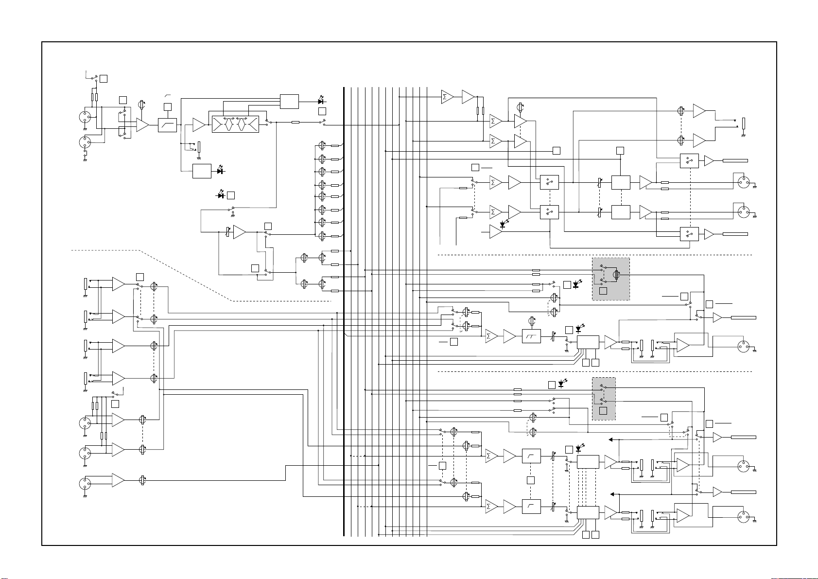
System Block Diagram
+48V
+48V
INPUT
PHASE
SENS
FX RET 2
HOUSE
SENS
100Hz
FX RET 1
MIC
INPUT
SPLIT
FX RET 1
LEFT
FX RET 1
RIGHT
FX RET 2
LEFT
FX RET 2
RIGHT
LEFT
HOUSE
MICS
RIGHT
T/B MIC
2
3
1
2
3
1
INPUT
2
3
1
2
3
1
2
3
1
SPLIT OUTPUT
(Internal Link)
Link - Grounded
No Link - Ground Lift
HOUSE
+48V
+48V
T/B SENS
INSERT
SIGNAL
DETECT
TIP: SEND
RING: RETURN
SIG
MUTE
FADER
▲▲▲
▲
EQ
9-12
PRE
PRE
MNTR 1-8
MNTR 9
MNTR 10
MNTR 11
MNTR 12
TALKBACK
PFL
T/B ALL
SOLO L
DIM ALL
SOLO R
WEDGE L
WEDGE R
PFL
SOLO L
SOLO/PFL
TRIM
PHONES
PEAK
DETECT
PEAK DETECT
& PFL ON
PFL
PHONES
MONITOR
1
2
3
4
5
6
1-8
7
8
9
9-10
PAN
10
11
11-1 2
PAN
12
SOLO R
OUT 11 OUT 12
RET1
RET2
TALKBACK SIGNAL
WEDGE
SOURCE
PFL/SOLO
ENABLE
T/B ALL
DIM ALL
MNTR
11-1 2
RET LEVEL
HIGH PASS
OFF-160Hz
MNTR
MASTER
FADER
SOLO
T/B
MASTER
WEDGE
DIM
SOLO L
DIM
DIM
WEDGE/SOLO
METER L
3
2
3
2
WEDGE
L
1
WEDGE
R
1
SOLO R
WEDGE/SOLO
METER R
MONO OUTPUT (1 of 8 Shown)
PAN
SOLO
MUTE
DIM
TB &
DIM
T/B
* FOH MODE SUBGROUPING
11-1 2
GRAPHIC EQ
(INSERT)
TO
FROM
MNTR
POST EQ
PRE EQ
METER
POST EQ
PRE EQ
METER
3
1
2
OUT (1-8)
STEREO OUTPUT (1 of 2 Shown)
* FOH MODE SUBGROUPING
MNTR
POST EQ
PRE EQ
GRAPHIC EQ
(INSERT)
TO
FROM
GRAPHIC EQ
(INSERT)
TO
FROM
METER
POST EQ
PRE EQ
METER
3
2
OUT
9(11)
METER
3
2
OUT
10 (12)
1
1
RET1
RET2
RET LEVEL
HOUSE
T/B ALL
DIM ALL
TALKBACK SIGNAL
60Hz
MNTR
FADER
MUTE
DIM
TB &
DIM
TB &
DIM
WEDGE
SOURCE
SELECT
(11 ONLY)
T/B
11-1 2
SOURCE
(12 ONLY)
WEDGE
SELECT
(9-10 only)
Page 14
Page 16
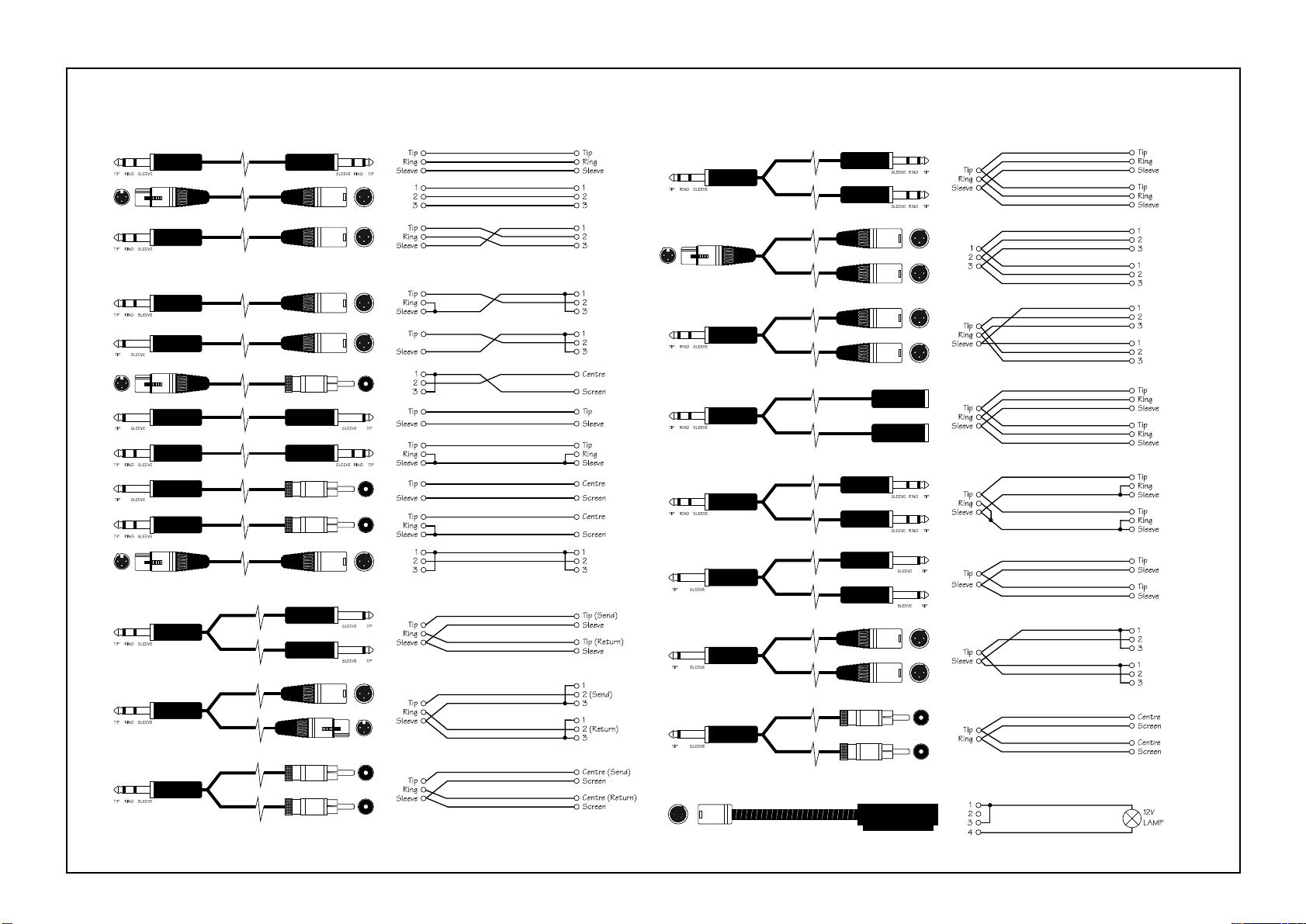
Connecting Leads
Balanced
Unbalanced
’Y’ Leads (Balanced)
Headphone Splitter
’Y’ Leads (Unbalanced)
Insert Leads
Lamp Connections
Page 15
Page 17
Control Position Sheet
You may freely copy this page to mark control positions to assist in resetting the desk between performances.
Page 18
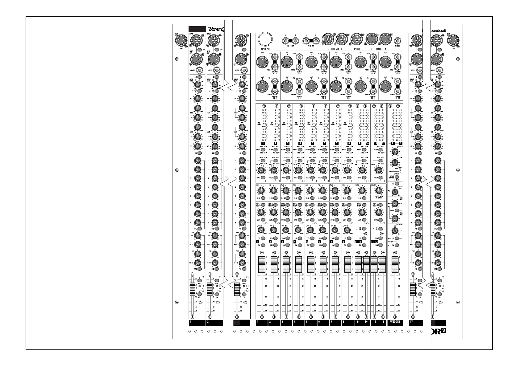
MONITOR 2 CONSOLE
Typical Starting Out Control Positions
INPUTS
2=CA%
Page 19
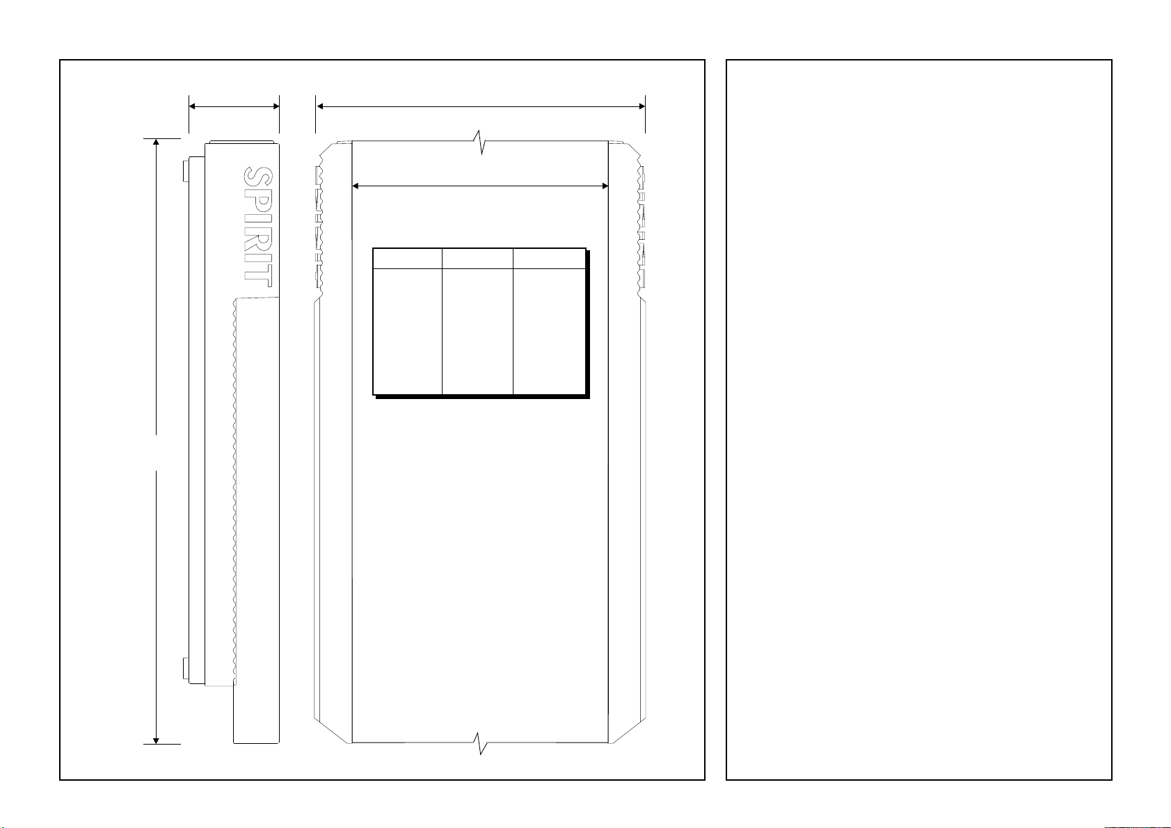
Dimensions
590.5 mm
(23.25")
87.5 mm
(3.44")
dim. ’x’
dim. ’y’
Width without end trim
(for flight case mounting)
Console
32 channel
40 channel
dim ’x’ dim ’y’
1454.6 mm
(57.27")
1708.6 mm
(67.27")
1370.6 mm
(53.96")
1624.6 mm
(63.96")
Specifications
Noise
Measured RMS, 22Hz to 22kHz Bandwidth. Inputs at unity gain and terminated 150W
Output Noise
24 inputs routed, sends down, master @ unity < -80dBu
EIN
Mic EIN @ max. gain (150W terminated) -129dBu
THD+N
Mic sens. -10dBu, Faders @ unity, send at max.,
+20dBu at all outputs @ 1kHz <0.005%
Crosstalk (@1kHz) Typical
Channel send range >90dB
Channel fader range >80dB
Mute attenuation >100dB
Adjacent output isolation >90dB
CMRR
Typical at max gain @ 1kHz >85dB
Typical at any gain @ 50Hz >65dB
Frequency Response
Input to output, medium gain, via output (Hi-pass filter off)
15Hz to 45kHz <-3dB
25Hz to 25kHz <-1dB
Typical Input and Output levels
Maximum output >+22dBu
Maximum signal into mic input +28dBu
Maximum signal into FX return & insert return +22dBu
Maximum sensitivity of FX return (Output faders @ unity) -15dBu
Maximum level into Talkback mic input +3dBu
Maximum level into House mic input +8dBu
Headphones (@ 200W) 150mW
Input and Output Impedance
Mic Input 1.8kW
FX returns 8.6kW
Monitor Outputs, Wedge & Inserts 75W
Page 18
Page 20

A Harman International Company
Part No: ZM0192
Part No. ZM0192-02
 Loading...