

Page 1

®
USER GUIDE
NANO SERIES
MULTI-CHANNEL ANALOG MIXING CONSOLE
M16 / M24
®
Page 2

2
NANO SERIES - M16 / M24
USER GUIDE
NANO SERIES - M16 / M24
USER GUIDE
®
For further information, please contact:
Harman International Industries Ltd, 8500 Balboa Blvd. Northridge,CA 91329 USA
Email: soundcraft@harman.com.
Soundcraft is a trading division of Harman International Industries Ltd. Information in this manual is subject to change without notice
and does not represent a commitment on the part of the vendor. Soundcraft shall not be liable for any loss or damage whatsoever
arising from the use of information or any error contained in this manual.
No part of this manual may be reproduced, stored in a retrieval system, or transmitted, in any form or by any means, electronic, electrical, mechanical, optical, chemical, including photocopying and recording, for any purpose without the express written permission
of Soundcraft.
Harman International Industries Limited
8500 Balboa Blvd. Northridge,CA 91329 USA
http://www.soundcraft.com
Please read this manual carefully before
using your mixer for the rst time!
Page 3

3
NANO SERIES - M16 / M24
USER GUIDE
®
For your own safety and to avoid invalidation of the
warranty please read this section carefully.
IMPORTANT SYMBOLS
Caution
Alerts the user to the presence of important
operating and maintenance (servicing) instructions
in the literature accompanying the appliance.
Warning
Alerts the user to the presence of uninsulated
“dangerous voltage” within the product’s enclosure
that may be of sufcient magnitude to constitute a
risk of electric shock to persons.
Protect your ears
Alerts the user that the product is capability to
produce sound which, when monitored through an
amplier or headphones, can damage hearing over
time.
SAFETY INSTRUCTIONS
• Read these instructions.
• Keep these instructions.
• Heed all warnings.
• Follow all instructions.
• Clean the apparatus only with a dry cloth.
• Do not install near any heat sources such as radiators,
heat resistors, stoves, or other apparatus (including
ampliers) that produce heat.
• Do not block any ventilation openings. Install in
accordance with the manufacturer’s instructions.
• Do not use this apparatus near water.
• Do not defeat the safety purpose of the polarized or
grounding type plug. A polarized plug has two blades
with one wider than the other. A grounding type plug has
two blades and a third grounding prong. The wide blade
or the third prong are provided for your safety. When
the provided plug does not t into your outlet, consult an
electrician for replacement of the obsolete outlet.
• Protect the power cord from being walked on or pinched
particularly at plugs, convenience receptacles and the
point where they exit from the apparatus.
• Only use attachments/accessories specied by the
manufacturer.
• Unplug this apparatus during lightning storms or when
unused for long periods of time.
• Refer all servicing to qualied service personnel.
Servicing is required when the apparatus has been
damaged in any way such as power-supply cord or plug
is damaged, liquid has been spilled or objects have fallen
into the apparatus, the apparatus has been exposed to
rain or moisture, does not operate normally, or has been
dropped.
• Use only with the cart, stand, tripod, bracket, or table
specied by the manufacturer, or sold with the apparatus.
When the cart is used, use caution when moving the cart/
apparatus combination to avoid injury from tip-over.
• No naked ame sources, such as lighted candles or
cigarettes etc., should be placed on the apparatus.
• No user serviceable parts. Refer all servicing to a
qualied service engineer, through the appropriate
Soundcraft dealer.
• The socket-outlet shall be installed near the equipment
and shall be easily accessible
THIS UNIT MUST BE EARTHED. Under no
circumstances should the mains earth be
disconnected from the mains lead.
All maintenance and service on the product
should be carried out by Soundcraft or its
authorized agents. Soundcraft cannot accept
any liability whatsoever for any loss or damage
caused by service, maintenance or repair by
unauthorized personnel.
WARNING: To reduce the risk of re or electric
shock, do not expose this apparatus to rain
or moisture. Do not expose the apparatus
to d ripping or splashing and do not place
objects lled with liquids, such as vases, on
the apparatus. No naked ame sources, such
as lighted candles, should be placed on the
apparatus.
Ventilation should not be impeded by covering
the ventilation openings with items such as
newspapers, table cloths, curtains etc.
Safety Instructions
Page 4

4
NANO SERIES - M16 / M24
USER GUIDE
NANO SERIES - M16 / M24
USER GUIDE
®
1. Soundcraft is a trading division of Harman International Industries Ltd.
End User means the person who rst puts the equipment into regular operation.
Dealer means the person other than Soundcraft (if any) from whom the End User purchased the Equipment, provided such a
person is authorised for this purpose by Soundcraft or its accredited Distributor.
Equipment means the equipment supplied with this manual.
2. If within the period of twelve months from the date of delivery of the Equipment to the End User it shall prove defective by
reason only of faulty materials and/or workmanship to such an extent that the effectiveness and/or usability thereof is materially affected the Equipment or the defective component should be returned to the Dealer or to Soundcraft and subject to the
following conditions the Dealer or Soundcraft will repair or replace the defective components. Any components replaced will
become the property of Soundcraft.
3. Any Equipment or component returned will be at the risk of the End User whilst in transit (Both to and from the Dealer or
Soundcraft) and postage must be prepaid.
4. This warranty shall only be available if:
a) The Equipment has been properly installed in accordance with instructions contained in Soundcraft’s manual; and
b) The End User has notied Soundcraft or the Dealer within 14 days of the defect appearing; and
c) No persons other than authorised representatives of Soundcraft or the Dealer have effected any replacement of parts maintenance adjustments or repairs to the Equipment; and
d) The End User has used the Equipment only for such purposes as Soundcraft recommends, with only such operating sup-
plies as meet Soundcraft’s specications and otherwise in all respects in accordance with Soundcraft’s recommendations.
5. Defects arising as a result of the following are not covered by this Warranty: faulty or negligent handling, chemical or elec-
tro-chemical or electrical inuences, accidental damage, Acts of God, neglect, deciency in electrical power, air-conditioning or
humidity control.
6. The benet of this Warranty may not be assigned by the End User.
7. End Users who are consumers should note their rights under this Warranty are in addition to and do not affect any other rights
to which they may be entitled against the seller of the Equipment.
Warranty
Page 5

5
NANO SERIES - M16 / M24
USER GUIDE
®
Introductions - M16 / M24 .................................................................................................................................................................... 06
Quick Start .......................................................................................................................................................................................... 07
Product Overview ............................................................................................................................................................................... 08
Controls and Features ........................................................................................................................................................................ 09
Effect Presets .....................................................................................................................................................................................17
Specications ..................................................................................................................................................................................... 18
Dimensions ......................................................................................................................................................................................... 19
Block Diagram .................................................................................................................................................................................... 20
Audio Connectors ............................................................................................................................................................................... 21
Index
Page 6

6
NANO SERIES - M16 / M24
USER GUIDE
NANO SERIES - M16 / M24
USER GUIDE
®
NANO Series multi-channel analog mixing console inherits legendary SOUNDCRAFT craftsmanship and is designed to meet
various application requirements from live performance, studio recording and xed installations. NANO Series owns two models in
its product portfolio: M16 (16 channels) and M24 (24 channels) and represents a new level of design, quality and performance.
M16 and M24 offer all the functionalities required for live mixing and studio recording: 8/16 mono input channels with ultra-low
noise discrete MIC preamp and +48V phantom power; 4 stereo input channels; each mono input channel equipped with 3-band
EQ and sweepable MID; each stereo input channel equipped with 4-band EQ; 4 auxiliary controls; 12-segment output level meter;
2-track input routable to main mix, control room / headphones.
M16 and M24 identify themselves for their cutting-edge and eye-catching appearance. The uniquely-designed Atmos Meter showcases SOUNDCRAFT’s dedication to engineering innovation and adds extra visual effects to live performance. The built-in USB
player supports MP3 playback and recording. 24-bit DSP processor provides up to 100 effect presets. Main mix out comes with a
7-band GEQ and an insert point.
M16 and M24 accommodate all the control and connection elements in a robust steel case and install connectors built from metallic
materials of highest industrial standards. Compact and ultra-light build, cutting-edge design, and acclaimed SOUNDCRAFT artisan-
ship make NANO an optimal choice for band gigging, studio recording or xed installation.
Features
• Ultra-low noise discrete MIC preamp with +48V phantom power.
• 8 / 16 mono input channels and 4 stereo input channels.
• Each input channel accepts balanced XLR MIC input and TRS LINE input.
• Low cut for each MIC input.
• Each mono input channel is equipped with 3-band EQ, sweepable MID and PEAK LED.
• 2 stereo input channels accept mono XLR or TRS input; 2 stereo input channels accepts RCA input.
• Each stereo input channel is equipped with 4-band EQ and PEAK LED.
• 8 compressor controls and 8 channel insert points.
• AUX 1 & AUX 2 send post/pre-fader signal for monitoring or external effects; AUX 3 & FX send post-fader for internal effects or
monitoring.
• PFL/MUTE and 60mm fader for each channel.
• GR1/2, GR3/4 and MAIN L-R buss assignment for each channel.
• MAIN MIX installs a pair of balanced XLR and a pair of unbalanced TRS connectors and can be equalized via a 7-band GEQ.
• MAIN MIX supports external effect insert.
• 24-bit DSP processor provides up to 100 effect presets.
• USB player for MP3 playback and recording.
• Switch-mode power supply for 100-240Voltage.
• USB port for MAIN MIX recording or playback through CH 15/16 (M16) or CH 23/24 (M24).
• Cutting-edge and eye-catching design. Uniquely-designed Atmos Meter adds extra visual effects to live performance.
Packing List
• NANO Series Mixing Console x 1
• Power Cord x 1
• User Guide (This document) x 1
Introductions - M16 / M24
Page 7
7
NANO SERIES - M16 / M24
USER GUIDE
®
WARNING: Read and follow all the SAFETY INSTRUCTIONS when setting up and operating the unit.
WARNING: Disconnect the power before setting up the unit.
WARNING: Under no circumstances should the mains earth be disconnected from the mains lead.
CAUTION: Turn all the input and output controls down before connecting the unit.
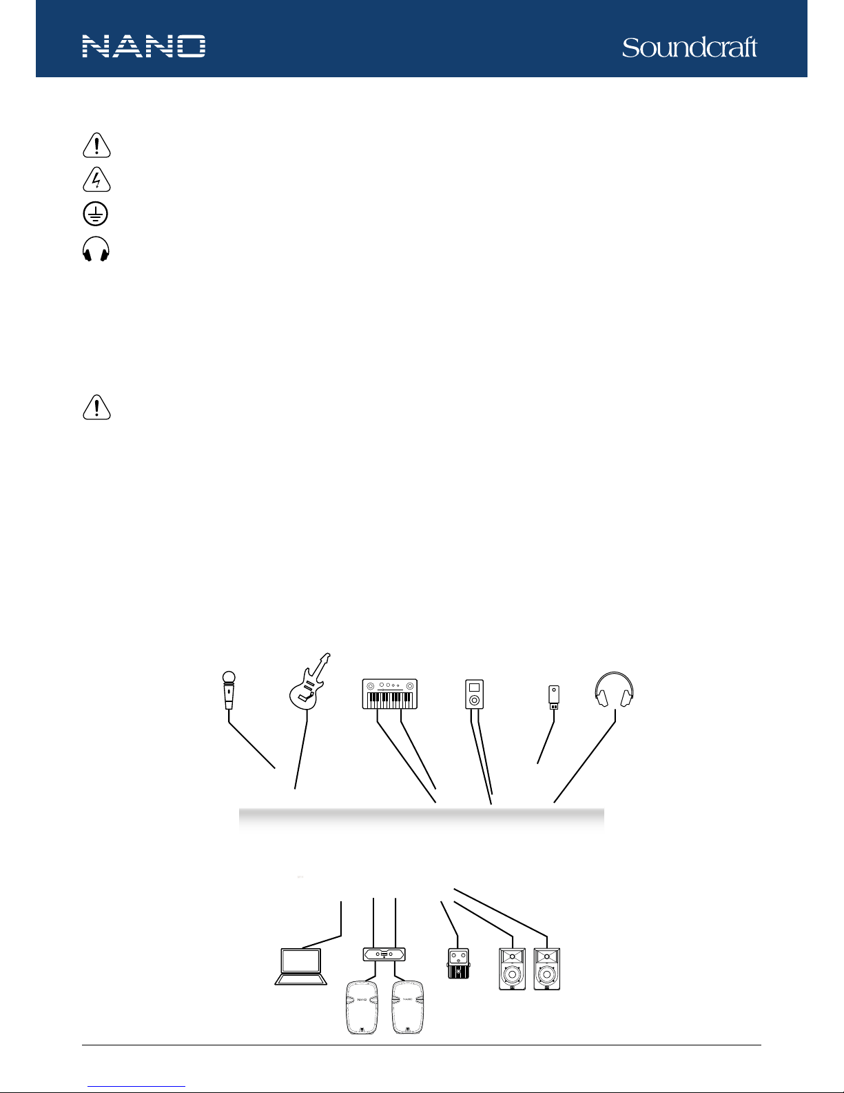
Please refer to the “Connection Example” to set up your audio system with NANO Series mixer:
1. Ensure the mixer and external devices to be connected are completely disconnected from power and all the input and output
controls of the mixer are turned down.
2. Connect external devices, e.g. micro-phones, ampliers, speakers, effects, etc.
3. Power on the devices and the mixer.
NOTE: To power on the system, please power on the mixer rst, then ampliers or powered speakers. To power off the
system, power off the ampliers or powered speakers rst, then the mixer.
4. Set the output level of your mixer or the connected amplier to no more than 75%.
5. Set the CONTROL ROOM / PHONE level to no more than 50%.
6. Position HI, MID and LOW EQ controls to the middle.
7. Position PAN / BAL controls to the center.
8. While speaking to the microphone (or playing the instrument), adjust the channel level control so that the CLIP LED blinks
occasionally. In this way, you will maintain an ideal headroom and dynamic range.
9. You can shape the tone of each channel by adjusting the EQ controls as desired.
10. Repeat the above steps for each active channel.
11. When the OUTPUT LEVEL meter registers the red segment, slightly lower the output signal level using the MAIN MIX control.
Quick Start
Microphone
Electronic Guitar
Electronic Keyboard
Media Player
USB Memory
Headphone
Footswitch
Monitor Speakers
Main Speakers
PC
Amplifier
Connection Example
Page 8

8
NANO SERIES - M16 / M24
USER GUIDE
NANO SERIES - M16 / M24
USER GUIDE
®
Product Overview
(M24 is shown)
Page 9

9
NANO SERIES - M16 / M24
USER GUIDE
®
The following features are applicable to both M16 and M24. In case where different features need to be described for each model,
M16 will be described rst, followed by M24
1. MIC INPUT JACKS (CH 1 to CH 11/12 for M16, CH 1 to CH 19/20 for M24)
These MIC input uses balanced XLR-type input jacks and are designed to accepts BALANCED or UNBALANCED signals. A +48V phantom power switch (at the rear panel) is
provided to power professional condenser mics.
NOTE: ONLY connect condenser microphones with the +48V phantom power
switched OFF, and ONLY switch on or off the +48V phantom power with all output
faders DOWN (∞), to prevent damage to the mixer or external devices.
2. LINE INPUT JACKS (CH 1 to CH 8 for M16, CH 1 to CH 16 for M24)
These LINE input use balanced TRS jacks and accept either BALANCED or UNBALANCED
signals.
NOTE: Unplug anything in the MIC input if you want to use this socket.
3. STEREO INPUT JACKS (CH 9/10 to CH 11/12 for M16, CH 17/18 to CH 19/20 for M24)
These L-R stereo input are organized in pairs of ¼” phone sockets. To connect a stereo device, plug both the left and right input
connectors. To connect a mono input signal, only use the left input, the output signal will appear on both sides.
4. LOW CUT
By pressing this button you will activate a 75Hz low frequency lter with a slope of 18dB per octave which reduces the hum noise
infected by the mains power supply or the stage rumble while using the microphone.
5. RCA INPUT JACKS (CH 13/14 to CH 15/16 for M16, CH 21/22 to CH 23/24 for M24)
These RCA input jacks are organized in stereo pairs. To connect a stereo device, plug both the
left and right input connectors.
6. HI-Z
Press the HI-Z switch will change the channel input to a high impedance input.
7. GAIN CONTROL
Adjusts the knob to set the input signal level. To achieve the best balance between S/N and dynamic range,
adjust the level so that the CLIP LED indicator light occasionally only on the highest input transients. For each
channel the MIC input adjustment range of the GAIN is 0-50dB and the sensitivity of line input is +20 to -30dB.
8. COMP CONTROL
Adjusts the amount compression applied to the channel. Turn the knob to the right to increase the compression ratio and the output gain will automatically adjusted. The result is smoother, more even dynamics
because louder signals are attenuated which the overall level is boosted.
Controls and Features
1
2
4
3
5
6
7
8
Page 10

10
NANO SERIES - M16 / M24
USER GUIDE
NANO SERIES - M16 / M24
USER GUIDE
®
9. LINE / USB SWTICH
Press down the button switches to the USB mode, then the USB signal will be sent to this
channel. Press up this button will send LINE IN signal to the channel.
10. LINE / USB PLAYER SWITCH
Press down the button will switch to the USB PLAYER mode, then the signal of USB PLAYER
module will be sent to the channel.
11. EQ CONTROLS
There are 3-band EQ with sweepable MID on all mono input channels (CH 1-8 for M16; CH
1-16 for M24): HI, MID and LOW band. There are 4-band xed frequency EQ on the stereo
channels (CH 9-16 for M16; CH 17-24 for M24): HI, HI-MID, MID-LOW and LOW band. All
bands provide up to 15dB of boost or cut.
HI
If you turn this control up, you will boost all frequencies above 12kHz (shelving lter). You will add transparency to vocals and guitar
and also make cymbals crispier. Turn the control down will cut all frequencies above 12kHz. In such way, you can reduce sibilance
of human voice or reduce the hiss of a tape player.
MID
This is a peaking lter and boosts or cuts frequencies from 100Hz to 8kHz depending on the position of the MID control. This control will affect especially upper male and lower female vocal ranges and also the harmonics of most musical instruments.
HI-MID
This control gives you up to 15dB boost or cut at 3kHz. It is useful for controlling voice and can accurately polish your performance
via adjusting this knob.
MID-LOW
This control gives you up to 15dB boost or cut at 500Hz.
LOW
If you turn this control up, you will boost all frequencies below 80Hz. This will add more punch to bass drum and bass guitar and
make the vocalist more “macho”. Turn it down, you will cut all frequencies below 80Hz. This will reduce low frequency vibrations
and resonance thus preserving the life of your woofers.
12. EQ ON/ EQ OFF SWITCH
This switch allows user to engage or bypass the EQ section in signal path. It can be used to make A/B comparisons between
equalized and non-equalized signals. It also can be used to apply equalized at a certain point of the show, excluding it when it’s not
necessary.
Controls and Features
9
10
11
12
Page 11

11
NANO SERIES - M16 / M24
USER GUIDE
®
13. AUX SEND CONTROLS
These four controls are used to adjust the level of the respective signal sent to AUX bus and the
adjustable range is from -∞ to +10dB.
14. PRE / POST SWITCH
Use the button to switch AUX 1 and AUX 2 to PRE/POST fader. This is helpful when AUX 1 and/or
AUX 2 are used for monitoring or effect & sound processor input. AUX 3 and AUX 4 are congured as
POST fader.
15. PAN / BAL CONTROL
The PAN control moves a mono signal source from left to right. The BAL control moves the whole
stereo image from left to right.
16. MUTE
Each channel is equipped with a MUTE button. When the button is pressed down, it equals to turning
the fader down, and can mute the corresponding channel output except for the PRE AUX sends,
channel INSERT send and PFL. The MUTE LED will illuminate when the MUTE button is engaged.
17. SIG / CLIP
The SIG LED illuminates when there is signal present in the channel. The CLIP LED will indicate
when the signal is about to clip or distort.
18. CHANNEL LEVEL FADER
The 60mm fader allows precise balancing of the various channel signals being mixed to the main
output. The adjustable range is from -∞ to +10dB.
19. GR 1-2 / GR 3-4 / L-R
Each channel provides three push-buttons: GR 1-2, GR 3-4 and L-R, which can be considered as signal assignment switches. For
instance, press the GR 1-2 down and the channel signal will be assigned to GROUP 1-2. You can depend on the PAN control to
adjust the amount of channel signal sent to the GROUP 1 versus GROUP 2. When the PAN control is turned to completely left,
then the signal will be controlled by GROUP 1 only and vice versa. Likewise, pressing the GR 3-4 or L-R will assign the channel
signal to GROUP 3-4 or MAIN MIX L-R, and will also be affected by the PAN switch.
20. PFL
Each channel is equipped with a PFL switch. When pressed down, the channel signal will be routed to CTRL ROOM / PHONES
outputs and the PFL LED will illuminate.
Controls and Features
13
14
15
16
18
17
20
19
Page 12

12
NANO SERIES - M16 / M24
USER GUIDE
NANO SERIES - M16 / M24
USER GUIDE
®
21. GROUPS LEVEL FADER
These 60mm faders are used to set the nal levels of signals sent to GROUP
OUT. The adjustable range is from -∞ to +10dB.
22. MAIN MIX LEVEL FADER
The 60mm fader sets the amount of signal sent to the MAIN MIX OUTPUT. The
adjustable range is from -∞ to +10dB.
23. DIGITAL EFFECTS
The LCD screen displays the effect preset selected.
24. PARAMETER (PRESS)
Rotate the knob to select the desired effect from the 100 preset options, which in-
clude Echo, Vocal, Plate and versatile dual-effect combinations. When you are satised with the selection, push the knob to conrm
the selection, then the LCD screen stops ashing.
25. FX / MUTE
Press down the button to disable the internal effect processor. In this
case the red PEAK LED will be on permanently.
26. FX TO AUX 1 / 2
The two knobs assign the FX signals to their respective AUX 1 or
AUX 2.
27. AUX SEND
These four controls are used to determine the master AUX SEND
levels. The adjustable range of each control is from -∞ to +10dB.
When external effect units which have no input gain control are connected to the mixer, you will get an extra +10dB gain from these AUX
SEND outputs. As for AUX 4, it also provides level adjustment for the
internal effect signal.
28. FX OUT
This control is used to determine the internal DSP module levels and
FX SEND output. The adjustable range is from -∞ to +10dB.
29. FX TO MAIN
This control is used to assign the signal from FX to MAIN MIX output. The adjustable range is from -∞ to +10dB.
30. OUTPUT LEVEL METER
The 12-segment three-color LED meter are provided to monitor the overall output signal level. Aim to keep the signal within the
Controls and Features
21 22
23
32
33
24
25
26
27
28 29
30
31
Page 13

13
NANO SERIES - M16 / M24
USER GUIDE
®
amber segments at peak levels for best performance and avoiding overloading. When any PFL switch is pressed down on any
channel, the PFL below the meter will illuminate.
31. MAIN / GR & GR 1/2 / GR 3/4
When the MAIN / GR button is released, the signal from the MAIN MIX output will be monitored. When the MAIN / GR button is
pressed down, the signal from the GROUP output will be monitored: release the GR 1/2 / GR 3/4 button to monitor signal from the
GR 1 / 2 output, or press the GR 1/2 / GR 3/4 button to monitor signal from the GR 3 / 4 output.
32. PHONES
This control is used to adjust the signal present at the PHONEs output. The adjustable range is from -∞ to +10dB.
33. CONTROL ROOM
This control is used to adjust the signal present at the CONTROL ROOM output. The adjustable range is from -∞ to +10dB.
34. POWER LAMP SOCKET
The standard-A USB power socket supplies power of 5.0V 500mA
and can be connected to USB-powered/chargeable peripherals
like a USB lamp.
35. PHONES
The phone output appears on a ¼” TRS jack connector and is
used to send the mix signal to a pair of headphone.
36. STEREO GRAPHIC EQ
The 7-band STEREO GRAPHIC EQ is used to modify the frequency “contour” of the MAIN MIX L-R. Each one of the faders will
boost or attenuate (+/- 12dB) the selected frequency at a preset
bandwidth. When all the faders are in the center position, the
output of the equalizer is at response.
37. PWR LED
This LED illuminates when the mixer is properly powered on.
38. +48V LED
This LED illuminates when the phantom power (at the rear panel) is switched on.
39. EQ OFF / ON
Press down the switch will engage the Stereo Graphic EQ for the MAIN MIX. Release the switch will bypass the Stereo Graphic
EQ.
Controls and Features
34 35
36
39 38 37
Page 14

14
NANO SERIES - M16 / M24
USER GUIDE
NANO SERIES - M16 / M24
USER GUIDE
®
40. MAIN MIX OUTPUT
These stereo outputs are supplied
with a pair of balanced XLR connectors and a pair of unbalanced
¼” phone jacks and are controlled
by the MAIN MIX LEVEL fader.
41. MAIN INSERT
The MAIN INSERT installs a pair
of ¼” TRS jacks and are used to
connect processors such as compressors, equalizers, etc. When an external processor are connected, the Main stereo signal will
be taken out after the main bus and returned into the MAIN MIX output before the MAIN MIX fader.
42. FX OUT
The FX OUT installs a pair of ¼” TRS jack and are used to send signal from FX mix buss to external devices.
FOOT SW.
This ¼” TRS jack is used to connect an external footswitch, which has the same function as FX MUTE button.
43. CTRL ROOM
These ¼” sockets sends signal to studio monitor speakers or a second set of PA.
44. GROUP OUT
These ¼” TRS jacks are
used to send signals from
GROUP 1-4 busses to
external devices.
45. AUX SEND
These ¼” phone jacks are
used to send signal from
AUX 1-4 busses to external
devices such as effects.
46. INSERT
The channel INSERT point uses a ¼” jack and is a break in the channel signal path just before the EQ section, allowing limiters,
compressors, special equalizers or other signal processing units to be added in the signal path.
Controls and Features
40 41 42 43 44 45 46
Page 15

15
NANO SERIES - M16 / M24
USER GUIDE
®
47. AC INPUT
Connect the mixer to the main AC with the
supplied AC cord. Please check the voltage available in your country and how the
voltage for your mixer is congured before
attempting to connect your mixer to the main
AC.
NOTE: Always replace the mains
fuse only with the correct value fuse,
as marked on the rear panel.
48. POWER SWITCH
This switch is used to turn on or off the main power of the mixer.
49. +48V PHANTOM POWER SWITCH
When the switch is turned on, +48V phantom power will be available to the XLR MIC inputs, to which professional condenser
microphones can be connected.
NOTE: ONLY connect condenser microphones with the +48V phantom power switched OFF, and ONLY switch on or off the
+48V phantom power with all output faders DOWN, to prevent damage to the mixer or external devices.
50. USB IN/OUT
This USB port is used to connect the mixer to work with a digital audio system or computer-based digital audio workstation for
playback or recording. When it is playback mode, it connects to the stereo channel of CH 13/14 of M16 or CH 21/22 of M24.
51. USB PLAYER
The USB PLAYER can be used to playback MP3 soundtracks from or record
MAIN MIX in MP3 format to a USB stick connected.
a. USB PORT
This USB port is used to connect a USB memory stick for playback and
recoding.
b.
PRE
When the USB player is in pause state, press this button will return to the previous track and remain the pause state. When the
player is in play state, press this button will return to the previous track and remain the play state. When the USB player is in play
state, press the button for 2 seconds, the player will switch to soundtracks in the previous media le stored in the USB memory;
press the button for more than 2 seconds, the player will switch among media les stored in the USB memory.
c.
NEXT
When the USB player is in pause state, press this button will go to the next track and remain the pause state. When the player is
in play state, press the button will go to the next track and remain the play state. When the USB player is in play state, press the
Controls and Features
47 48 49 50
abh c d
e
f
g
Page 16

16
NANO SERIES - M16 / M24
USER GUIDE
NANO SERIES - M16 / M24
USER GUIDE
®
button for 2 seconds, the player will switch to soundtracks in the next media le stored in the USB memory; press the button for
more than 2 seconds, the player will switch among media les stored in the USB memory.
d.
RPT
Press the button to select from the following repeat modes for the player.
• When
appears on the LCD screen, all the tracks in the USB memory stick will be repeated.
• When
appears on the LCD screen, one track (the current track) will be repeated.
• When A appears on the LCD screen, the tracks will be played at random.
• When no symbol appears on the LCD screen, the tracked will be played according to their order.
e.
PLAY / PAUSE
Press the button to start playing or pause the player.
f. REC
When the USB player is in use, press the REC button will switch the player to the recording mode. Press the REC button again will
start recording.
When the USB player is in recording mode, the rest player functions will not be opera-table until the recording mode is terminated
through the POWER button.
In case the “Err” appears on the LCD screen, it means an error happens to recording. In such situation, press POWER button to
stop recording.
g. POWER
Press and hold the button for 2-3 seconds will turn on or off the USB player.
h. DISPLAY
The LCD screen displays all the USB player information and status.
Controls and Features
Page 17

17
NANO SERIES - M16 / M24
USER GUIDE
®
NO. PRESET DESCRIPTION PARAMETER
00~09 Echo
Reproduce the sound in input on the output after a lapse
of time or delay.
Delay time: 145~205ms
10~19 Echo+Verb Echo with room effect.
Delay time: 208~650ms
Decay time: 1.7~2.1s
20~29 Tremolo Amplitude modulation of the signal. Rate: 0.6 Hz~5 Hz
30~39 Plate
Simulate the transducers sound like classic bright vocal
plate.
Decay time: 0.9s~3.6s
40~49 Chorus
Recreate the illusion of more than one instrument from a
single instrument sound.
Rate: 0.92Hz~1.72Hz
50~59 Vocal Simulate a small space with slight decay time.
Rev. decay time: 0.8~0.9s
Pre-delay: 0~45ms
60~69 Rotary
Simulate the sound effect achieved by rotating horn
speakers and a bass cylinder.
Modulation depth: 20%~80%
70~79 Small Room Simulate a bright studio room.
Decay time: 0.7~2.1s
Pre-delay: 20~45ms
80~89 Flanger+Verb
Simulate to play with another person carrying out the
same notes on the same instrument and reverb.
Decay time: 1.5~2.9s
Rate: 0.8Hz~2.52Hz
90~99 Large Hall Simulate a large acoustic space of the sound.
Pre-delay: 23~55ms
Decay time: 3.6~5.4s
Effect Presets
Page 18

18
NANO SERIES - M16 / M24
USER GUIDE
NANO SERIES - M16 / M24
USER GUIDE
®
M16 M24
Noise
Hum & noise <-80 dB @ 20 Hz~22 KHz A-weighted, 1 channel & main level: 0 dB, the other: minimum
Crosstalk
Crosstalk <-80 dB @ 0 dB 20 Hz~22 KHz A-weighted, main level: 0 dB, the other: minimum
Frequency Response
Mic/Line Input to any output, 20 Hz-20 kHz <1 dB <1 dB
THD + N
Mic sens. -30 dBu, +20 dBu at all outputs @ 1 kHz <0.006% <0.006%
CMRR
Typical @ max gain @ 1 kHz >80 dB >80 dB
Typical @ any gain @ 50 Hz >60 dB >60 dB
Input & Output Impedance
Mic Input 1.8 kΩ 1.8 kΩ
Line Input 23.6 kΩ 23.6 kΩ
Stereo Input 20 kΩ 20 kΩ
Mix, Aux and Insert Sends 120 Ω 120 Ω
Input & Output Levels
Mic Input max. level +20 dBu +20 dBu
Line Input max. level +30 dBu +30 dBu
Stereo Input max. level +30 dBu +30 dBu
Headphones (@ 200 Ω) 150 mW 150 mW
Compressor
Gain 0 - 9 dB 0 - 9 dB
Threshold
20 dB →↓5 dB 20 dB →↓5 dB
USB 2.0 (Standard B)
Inputs / Outputs 2-in, 2-out 2-in, 2-out
Bit Depth 16-bit 16-bit
Sampling rate 32 kHz / 44.1 kHz / 48 kHz 32 kHz / 44.1 kHz / 48 kHz
USB Player
Inputs / Outputs 2-in, 2-out 2-in, 2-out
Record sampling rate 44.1 kHz 44.1 kHz
Power Consumption
Mains voltage 100 V-240 VAC, 50/60 Hz, universal input 100 V-240 VAC, 50/60 Hz, universal input
Physical
Net weight 6.59 kg 9.18 kg
Gross weight 8.2 kg 11.2 kg
Dimensions 504.62 x 425.00 x 88.34 mm 724.62 x 425.00 x 88.34 mm
Specications
Page 19

19
NANO SERIES - M16 / M24
USER GUIDE
®
Dimensions
M16
M24
Measured in mm
504.62
724.62
88.34
74.46
425
5.8
o
5.8
o
425
Page 20

20
NANO SERIES - M16 / M24
USER GUIDE
NANO SERIES - M16 / M24
USER GUIDE
®
3-BAND EQ
12K100Hz-8kHz80
LEFT-BUS
RIGHT-BU
S
AUX1
AUX2
RIGHT
LEFT
AUX1
AUX2
AUX1
LEFT
RIGHT
+/-15db
4-BAND EQ
12K50080
+/-15db
MAIN MIX
2
1
3
LEFT(XLR)
LEVEL
LO
(FREQ)
HI
AUX2
AUX1
FADER
POST
PRE
BAL
FADER
3c5e1a
4d
2b
LE
FT(MONO)
3c5e1a
4d
2b
RIGHT
-+-
+
PFL-L
PFL-R
PFL-R
EFX SEND
LEFT
RIGHT
AUX1
AUX2
DFX SEND
SOLO CTR
SOLO CTRL
GR1
GR2
GR1
GR2
GR2
GR1
CONTROL ROOM SOURCE
ASSIGN
MID
LO
M-H
HI
L-M
3K
12K50080 3K
GR3
GR4
GR3
GR4
AUX3
AUX4
GR4
GR3
AUX3
AUX4
MUTE
AUX4
AUX3
AUX3
AUX4
2
1
3
MIC IN
+48V
PHANTOM
-
+
POWER
RIGHT
LEFT
GR2
GR1
ASSIGN
GR4
GR3
AUX2
POST
PRE
AUX3
AUX4
STEREO TRIM
MUTE
AUX1
CTRL/L
CTRL/R
(AUX SEND 2/3 IDENTICAL)
3c
5e
1a
4d
2b
AUX/DFX SEND
3c
5e
1a4d2b
AUX SEND 1/2
/3
4-BAND EQ
+/-15db
CTRL/L
CTRL/R
POST
PRE
CH1-CH8 FOR M16
CH9-CH12 FOR M16
CH17-CH20 FOR M24
CH1-CH16 FOR M24
213
MIC IN
+48V
PEAK
PHANTOM
GAIN
-
+
POWER
MIC GAIN:0~50dB
LINE IN GAIN:-20dB~30dB
(TRIM)
3c
5e
1a4d2b
LINE IN
LO CUT
COPM.
SIG
3c
5e
1a
4d
2b
LEFT(TRS)
3c
5e
1a4d2b
RIGHT(TRS)
AUX SEND1
LEVEL
BA
BA
BA
BA
BA
BA
BA
BA
HI-Z
PFL-L
SOLO CTRL
CH1~8
CH1~4
PFL-R
PFL-L
SOLO CTRL
PEAK
SIG
EQ BYPASS
EQ BYPASS
PAN
4-BAND EQ
12K50080
+/-15db
BAL
FADER
LO
M-H
HI
L-M
3K
12K50080 3K
RIGHT
LEFT
GR2
GR1
ASSIGN
GR4
GR3
AUX2
POST
PRE
AUX3
AUX4
STEREO TRIM
MUTE
AUX1
4-BAND EQ
+/-15db
BA
BA
BA
BA
PFL-R
PFL-L
SOLO CTRL
PEAK
SIG
EQ BYPASS
RIGHT
LEFT
+
USB BOARD
PLAYBACK
RECORD
MAIN OUT LEFT
MAIN OUT RIGHT
TO PC
CH13-CH14 FOR M16
CH21-CH22 FOR M24
+
4-BAND EQ
12K50080
+/-15db
BAL
LEVEL
LO M-H HIL-M
3K
12K50080 3K
GR2
GR1
ASSIGN
GR4
GR3
AUX2
POST
PRE
AUX3
AUX4
STEREO TRIM
MUTE
AUX1
4-BAND EQ
+/-15db
BA
BA
BA
BA
PFL-R
PFL-L
SOLO CTRL
PEAK
SIG
EQ BYPASS
CH15-CH16 FOR M16
CH23-CH24 FOR M24
USB PLAYER
PLAYBACK
RECORD
MAIN OUT LEFT
MAIN OUT RIGHT
TO USB DISK
213
RIGHT(XLR)
AUX SEND4
LEVEL
BA
AUX4
GR1
(GR 3/4 IDENTICAL)
3c
5e1a4d
2b
GR1 OUT
GR1-2
LEVEL
BA
GR2
3c5e1a
4d
2b
GR2 OUT
BA
GR1-2 TO MIX
RIGHT
LEFT
RIGHT
LEFT
GR1 OUT
GR2 OUT
GR3 OUT
GR4 OUT
MAIN OUT LEFT
MAIN OUT RIGHT
PF
L-L
PF
L-R
S
OLO CTRL
SOLO ACTIVE
PFL-L
PFL-R
SOLO CTRL
LEVEL
PHONES
LEVEL
CTRL ROOM
BA
BA
BA
BA
3c
5e
1a
4d
2b
CTRL RIGHT
3c5e1a
4d
2b
CTRL LEFT
3c
5e1a4d
2b
PHONES
LEFT METER
RIGHT METER
BA
BA
PRESETS
MUTE
FX OUT L
FX OUT R
AUX1
AUX2
RIGHT
LEFT
EFX SEND
EFX SEND FX IN
DSP MODULE
AUX2
AUX1
AUX4
AUX3
AUX2
AUX1
AUX4
AUX3
AUX2
AUX1
AUX4
AUX3
DFX TO MAIN
DFX TO AUX1
DFX TO AUX2
CONTROL
3c
5e
1a
4d
2b
LEFT INSERT
3c
5e
1a4d2b
RIGHT INSERT
7-BAND EQ
7-BAND EQ
EQ BYPASS
3c
5e
1a
4d
2b
INSERT
FOR CH1-CH8
RIGHT
LEFT
+
+
Block Diagram
Page 21

21
NANO SERIES - M16 / M24
USER GUIDE
®
Sleeve=Ground/Screen
Tip=Signal
Sleeve=Ground/Screen
Ring=Return Signal (Connected together)
To Channel Insert
To Tape or FX Input
'Tapped' Connection Direct Output Lead
(Enables the Insert t o be used a saDirect Output
while maintaining the channel signal flow)
Sleeve
Sleeve=Ground/Screen
Ring=Return Signal
Tip=Send Signal
To Channel Insert
To Processor Input
To Processor Output
Ring
Tip
Y-Stereo lead for insert Connection
(To be used when the processor does not employ a
single jack connection for the In/Out Connections)
Strain Clamp
Sleeve
Tip
Ring
Sleeve=Ground/Screen
Ring=Right Signal
Tip=Left Signal
Use for Headphone, Stereo Return
1/4" Stereo (TRS) Jack Plug
2=Hot(+)
3=Cold(-)
1=Ground/Screen
(seen from soldering side)
Use for Balanced Mic Inputs
(For unbalanced use, connect pin1to 3)
3-pin XLR Male Plug
1
2
3
2=Hot(+)
3=Cold(-)
1=Ground/Screen
Use for Main output
(For unbalanced use, leave pin3unconnected)
3-pin XLR Line Socket
(seen from soldering side)
1
2
3
Sleeve
Tip
Ring
Ring=Return Signal
Sleeve=Ground/Screen
Tip=Send Signal
Use for Pre-Gain Channel Inserts
1/4" Stereo (TRS) Jack Plug
Strain Clamp
Sleeve
Tip
Sleeve=Ground/Screen
Tip=Signal
Use for Mono Line In, Mono 1/4"Jack Plugs
1/4" Mono (TS) Jack Plug
Strain Clamp
Audio Connectors
Page 22

®
NANO SERIES - M16 / M24
USER GUIDE
09/2017
 Loading...