

Page 1
Operating Instructions
XGS 116(w)/126(w)/136(w)
Page 2
Operating Instructions
Foreword
We are pleased to welcome you as a new customer of our Sophos XGS appliances.
To install and configure the hardware appliance you can use the following documents:
Hardware Quick Start Guide: Connection to the system peripherals in a few steps
Operating Instructions: Notes on the security and commissioning of the hardware
appliance
Sophos Firewall How-To Library: Installing and configuring the software appliance
The Hardware Quick Start Guide and the Safety Instructions are also delivered in printed
form together with the hardware appliance. The instructions must be read carefully prior to
using the hardware and should be kept in a safe place.
You may download all user manuals and additional documentation from the support
webpage at: sophos.com/support
Security Symbols
The following symbol and its meaning appears in the Hardware Quick Start Guide, Safety
Instructions and in these Operating Instructions.
Caution and Important Note. If these notes are not correctly observed:
Ì This is dangerous to life and the environment
Ì The appliance may be damaged
Ì The functions of the appliance will be no longer guaranteed
Ì Sophos shall not be liable for damages arising from a
failure to comply with the Safety Instructions
Designed Use
The hardware appliances are developed for use in networks. The XGS
116(w)/126(w)/136(w) models may be operated as a standalone appliance. The hardware
appliance can be used in commercial, industrial and residential environments.
The XGS 116(w)/126(w)/136(w) models belongs to the appliance group B.
The hardware appliance must be installed pursuant to the current installation notes.
Otherwise failure-free and safe operation cannot be guaranteed. The EU declaration of
conformity is available at the following address:
Sophos Technology GmbH
Amalienbadstr. 41/Bau 52
76227 Karlsruhe
Germany
2XGS 116(w)/126(w)/136(w)
Page 3
Operating Instructions
CE Labeling, FCC and Approvals
The XGS 116(w)/126(w)/136(w) appliance comply with CB, CE, UL, FCC Class B, ISED,
VCCI, CCC, KC, BSMI, RCM, NOM, Anatel.
Important Note: For computer systems to remain CE and FCC compliant, only CE and FCC
compliant parts may be used. Maintaining CE and FCC compliance also requires proper
cable and cabling techniques.
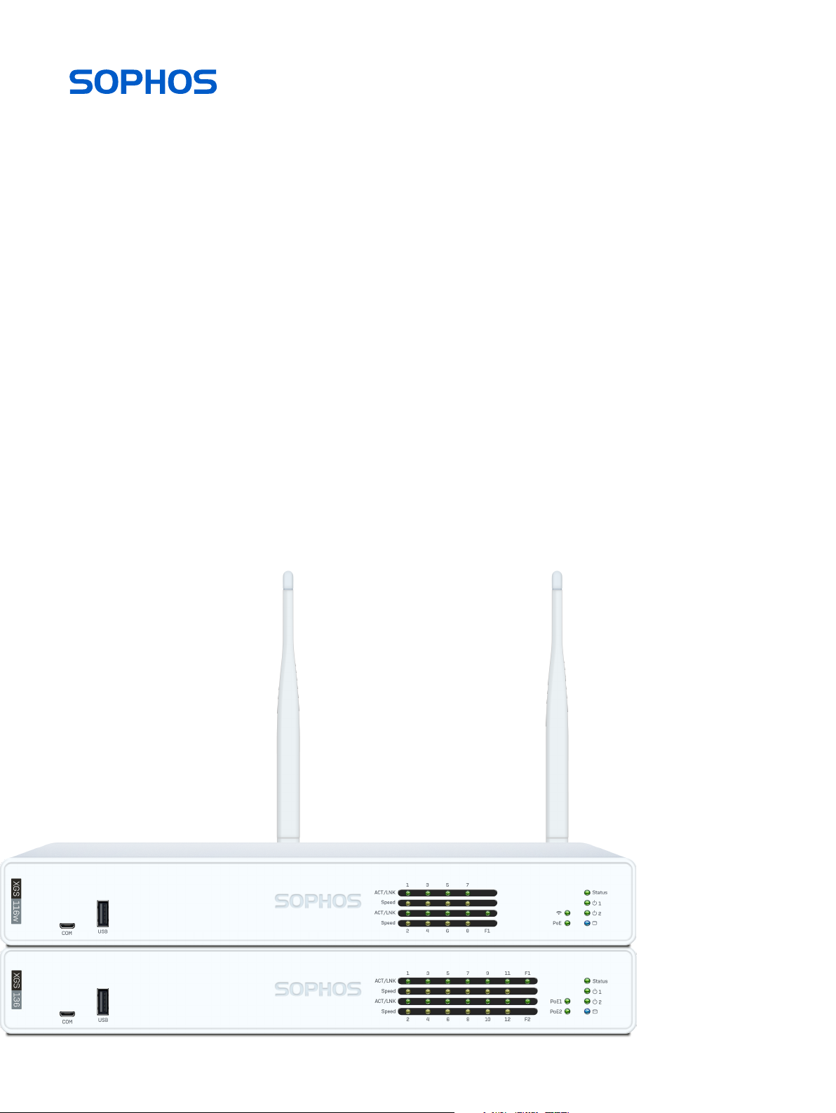
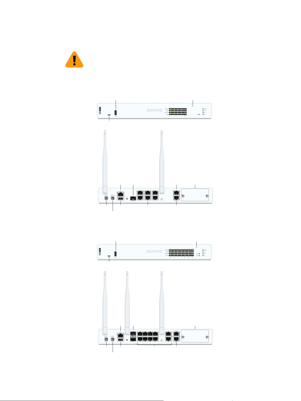
Operating Elements and Connections
XGS 116(w)
USB 2.0
1 x COM
Micro USB
1 x
2 x external antenna
(XGS 116w only)
Status LEDs
(w-model has
additional WiFi LED)
1 x COM
(RJ45)
Connector for optional 2nd
redundant power supply
F1 1 x SFP
fiber port
1 x USB 3.0Power supply
XGS 126(w)/136(w)
1 x
USB 2.0
1 x COM
Micro USB
3 x external antenna
(XGS 126w/136w only)
F1–F2 2 x
1 x COM
(RJ45)
SFP fiber
ports
6 x GbE copper port
1 x GbE
copper port
1 x GbE
PoE port
Optional module
expansion bay
Status LEDs
(w-model has
additional WiFi LED)
Optional module
expansion bay
1 x USB 3.0Power supply
Connector for optional 2nd
redundant power supply
10 x GbE copper port
2 x 2.5 GbE PoE port (136(w))
2 x GbE PoE port (126(w))
3XGS 116(w)/126(w)/136(w)
Page 4

Operating Instructions
Technical Specifications
XGS 116(w) XGS 126(w) XGS 136(w)
Physical Specification
#Fixed Ethernet Ports 8 x GE (1 x PoE)
Expansion Slots 1 1 1
Connectivity Modules
(Optional)
(Modules are supplied
with antennas)
#Cores/Threads
main CPU
Main Memory 4 GB DDR4 6 GB DDR4 8 GB DDR4
NPU Memory 4 GB DDR4 4 GB DDR4 4 GB DDR4
Storage 64 GB SSD 64 GB SSD 64 GB SSD
Power Supply External auto-ranging
Power Consumption
(idle - typical)
AC Power (Max. PoE
Enabled) Addition
Power Consumption
(full load - typical)
Mounting Wall, Rack, DIN-Rail Wall, Rack, DIN-Rail Wall, Rack, DIN-Rail
Dimensions
Width x Depth x Height
Weight (kg)
unpacked/packed
Environmental
Noise level (avg.)
(typical/max)
Operating Temperature 0°C–40°C 0°C–40°C 0°C–40°C
Storage Temperature -20°C–70°C -20°C–70°C -20°C–70°C
Opertional/Storage
Humidity
Altitude 2000m 2000m 2000m
MTBF (hours)
(Telcordia SR332 Issue 3)
Certifications
(Safety, EMC)
30 W / 102 BTU/hr (116w)
60 W / 205 BTU/hr (126w)
2.2 kg / 4.85 lbs (unpacked)
1 x SFP
3G/4G Module
2nd Wi-Fi 5/802.11ac
Single radio module
(XGS 116w)
4/4 2/4 2/4
AC-DC 100-240VAC,
2.5A@50-60 Hz,
12VDC, 12.5A, 150W
28 W / 96 BTU/hr (116)
38 W / 130 BTU/hr 76 W / 260 BTU/hr 76 W / 260 BTU/hr
57 W / 195 BTU/hr (126)
320 x 213 x 44 mm 320 x 213 x 44 mm 320 x 213 x 44 mm
4.2 kg /9.26 lbs (packed)
29/43 dBA 29/43 dBA 29/43 dBA
10% - 90%
non-condensing
210.107 (XGS 116)
193.047 (XGS 116w)
CB, CE, UL, FCC, ISED,
VCCI, CCC, KC, BSMI,
RCM, NOM, Anatel
12 x GE (2 x PoE)
2 x SFP
3G/4G Module
2nd Wi-Fi 5/802.11ac
Single radio module
(XGS 126w)
External auto-ranging
AC-DC 100-240VAC,
2.5A@50-60 Hz,
12VDC, 12.5A, 150W
30 W / 202 BTU/hr (126)
32 W / 212 BTU/hr (126w)
59 W / 102 BTU/hr (126)
62 W / 109 BTU/hr (126w)
2.4 kg / 5.29 lbs (unpacked)
4.4 kg /9.70 lbs (packed)
10% - 90%
non-condensing
200.091 (XGS 126)
184.003 (XGS 126w)
CB, CE, UL, FCC, ISED,
VCCI, CCC, KC, BSMI,
RCM, NOM, Anatel
10 x GE
2 x 2.5G (2 x PoE)
2 x SFP
3G/4G Module
2nd Wi-Fi 5/802.11ac
Single radio module
(XGS 136w)
External auto-ranging
AC-DC 100-240VAC,
2.5A@50-60 Hz,
12VDC, 12.5A, 150W
30 W / 102 BTU/hr (136)
32 W / 109 BTU/hr (136w)
62 W / 212 BTU/hr (136)
62 W / 222 BTU/hr (136w)
2.4 kg / 5.29 lbs (unpacked)
4.4 kg /9.70 lbs (packed)
10% - 90%
non-condensing
200.091 (XGS 136)
184.003 (XGS 136w)
CB, CE, UL, FCC, ISED,
VCCI, CCC, KC, BSMI,
RCM, NOM, Anatel
Interfaces
LAN Ports Type Speed Comment
1–8 RJ45 10/100/1000 Mbps Port 8 on XGS 116(w) can be used to power a
9–10
(XGS 126(w)/136(w) only)
11–12
(XGS 126(w)/136(w) only)
F1 SFP 1 Gbps SFP transceivers are sold separately.
F2
(XGS 126(w)/136(w) only)
RJ45 100/1000 Mbps
RJ45 XGS 126(w):
100/1000 Mbps
XGS 136(w):
100/1000/2500 Mbps
SFP 1 Gbps SFP transceivers are sold separately.
connected device (e.g. access point, IP camera, or
IP Phone) via PoE with upto 30W (PoE 802.3at).
Both ports can be used to power a connected
device (e.g. access point, IP camera, or IP Phone)
via PoE with upto 30W (PoE 802.3at) each.
4XGS 116(w)/126(w)/136(w)
Page 5

Operating Instructions
Other Ports Type Comment
COM Micro USB [front]
RJ45 [back]
USB USB 2.0 [Type A] [front]
USB 3.0 (Type A) [back]
Expansion Bay Comment
3G/4G Module Can be used for Sophos XGS 3G/4G Module, which is
optionally available from your Sophos partner.
WiFi Module Can be used for Sophos XGS WiFi Module, which is
optionally available from your Sophos partner.
You can connect a serial console to the
Micro USB or RJ45 COM port to access
the CLI. Only one port can be used at any
time. If both ports are connected, then the
Micro USB port will take precedence.
The required connection settings are:
Ì Bits per second: 38,400
Ì Data bits: 8
Ì Parity: N (none)
Ì Stop bits: 1
You can connect a USB 2.0 and/or 3.0
compatible device to these ports (e.g. USB
thumb drive, UPS, 3G/4G dongles).
LED Status
LEDs on each RJ45 Ethernet Connector
ACT/LNK
(Left LED)
Green Solid 1. The Ethernet port has established link.
2. Good connection between the
Ethernet port and hub.
Flashing The adapter is sending or receiving network data.
Off 1. The adapter and switch are not receiving power.
2. No connection between both ends of network.
3. Network drivers have not been loaded
or do not function correctly.
Speed
(Right LED)
LEDs on each SFP Connector
ACT/LNK Green Solid 1. The SFP connector is receiving power.
LEDs (Front)
Storage Blue Flashing SSD is being accessed.
Status Green Solid Normal operation.
WiFi Green On WiFi is active.
Power 1 Green Solid Power adapter 1 in normal operation.
Power 2 Green Solid Power adapter 2 in normal operation.
Amber On If Ethernet port is operating at 1000 Mbps.
Green On If Ethernet port is operating at 100 Mbps.
Off If Ethernet port is operating at 10 Mbps.
2. Good connection between
the SFP port and hub.
Flashing The adapter is sending or receiving network data.
Off 1. The adapter and switch are not receiving power.
2. No connection between both ends of network.
3. Network drivers have not been loaded
or do not function correctly.
Flashing Device is booting up or shutting down.
Red Solid SSD or boot failure.
Flashing General error (please contact support).
Off WiFi is inactive.
Red Solid Power adapter 1 failed or disconnected.
Red Solid Power adapter 2 failed or disconnected.
5XGS 116(w)/126(w)/136(w)
Page 6

Operating Instructions
Putting into Operation
Caution: Risk of explosion if battery is replaced by an incorrect type. Dispose of used
batteries according to the instructions.
Scope of Supply
The supplied parts are indicated in the Hardware Quick Start Guide.
Mounting Instructions
The XGS 116/126/136 appliance can be placed on a stable horizontal surface or can
be mounted to a rack or you can hang it on the wall by using the optionally available
rackmount kit.
Warnings and Precautions
The appliance can be operated safely if you observe the following notes and the notes on
the appliance itself.
Rack Precautions
Ì Ensure that the leveling jacks on the bottom of the rack are fully extended
to the floor with the full weight of the rack resting on them.
Ì In single rack installation, stabilizers should be attached to the rack.
Ì In multiple rack installations, the racks should be coupled together.
Ì Always make sure the rack is stable before extending a component from the rack.
Ì You should extend only one component at a time—extending two or
more simultaneously may cause the rack to become unstable.
General Server Precautions
Ì Review the electrical and general safety precautions that came
with the components you are adding to your appliance.
Ì Determine the placement of each component in the rack before you install the rails.
Ì Install the heaviest server components on the bottom of the rack first, and then work up.
Ì Allow the hot plug hard drives and power supply modules to cool before touching them.
Ì Always keep the rack‘s front door, all panels and server components
closed when not servicing to maintain proper cooling.
6XGS 116(w)/126(w)/136(w)
Page 7

Operating Instructions
Rack Mounting Considerations
Ì Ambient operating temperature: If installed in a closed or multiunit rack assembly,
the ambient operating temperature of the rack environment may be greater than the
ambient temperature of the room. Therefore, you should install the equipment in an
environment compatible with the manufacturer’s maximum rated ambient temperature.
Ì Reduced airflow: Equipment should be mounted into a
rack with sufficient airflow to allow cooling.
Ì Mechanical loading: Equipment should be mounted into a rack so that a
hazardous condition does not arise due to uneven mechanical loading.
Ì Circuit overloading: Consideration should be given to the connection of the equipment
to the power supply circuitry and the effect that any possible overloading of circuits
might have on overcurrent protection and power supply wiring. Appropriate consideration
of equipment nameplate ratings should be used when addressing this concern.
Ì Reliable ground: Reliable grounding must be maintained at all times.
To ensure this, the rack itself should be grounded. Particular attention
should be given to power supply connections other than the direct
connections to the branch circuit (i.e., the use of power strips, etc.).
Connection and Configuration
How to connect the appliance is described in the Hardware Quick Start Guide. For
configuration you can follow the initial setup wizard described in the Web Admin Quick
Start Guide or cancel it and perform a manual setup (see the Sophos Firewall How-To
Library).
Serial Console
You can connect a serial console to either of the COM ports of the Sophos XGS hardware
appliances. You can use, for instance, the Hyperterminal terminal program which is
included with most versions of Microsoft Windows to log on to the appliance console. Use
an RJ45 to DB9 adapter cable or the provided USB cable to connect the console to your
hardware appliance.
The required connection settings are:
Ì Bits per second: 38,400
Ì Data bits: 8
Ì Parity: N (none)
Ì Stop bits: 1
Access via the serial console is activated by default on ttyS0. The connections of the
appliances and the respective functionality are listed in chapter ‘Operating Elements and
Connections’.
7XGS 116(w)/126(w)/136(w)
Page 8

Operating Instructions
United Kingdom and Worldwide Sales
Tel: +44 (0)8447 671131
Email: sales@sophos.com
© Copyright 2021. Sophos Ltd. All rights reserved.
Registered in England and Wales No. 2096520, The Pentagon, Abingdon Science Park, Abingdon, OX14 3YP, UK
Sophos is the registered trademark of Sophos Ltd. All other product and company names mentioned are
trademarks or registered trademarks of their respective owners.
21-04-08 OI-EN (PC)
North American Sales
Toll Free: 1-866-866-2802
Email: nasales@sophos.com
Australia and New Zealand Sales
Tel: +61 2 9409 9100
Email: sales@sophos.com.au
Asia Sales
Tel: +65 62244168
Email: salesasia@sophos.com
 Loading...