

Page 1
Quick Start Guide
XG 115(w)/125(w)/135(w) Rev. 3, XG 106(w) Rev. 1
Page 2

For more information about your device, scan the QR code or visit
www.sophos.com/get-started-xg
1. Before Deploying
Congratulations on the purchase of your Sophos XG device. This Quick Start Guide describes in short steps how to connect your
device and explains how to open the web-based Admin Console from your administration PC. The Admin Console allows you to
configure every aspect of the device.
Before you begin please confirm that you have a working Internet connection and make sure you have the account information
available that was provided by your ISP.
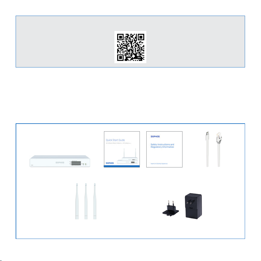
What is included in the box
This Quick Start Guide and Security NotesXG 106(w)/115(w)/125(w)/135(w)
XG 106w/115w - 2 antennas;
XG 125w/135w - 3 antennas
Quick Start Guide XG 115(w)/125(w)/135(w) Rev. 3, XG 106(w) Rev. 1
Micro USB cable
RJ45 Ethernet cable
Power Adapter (region specific)
1
Page 3
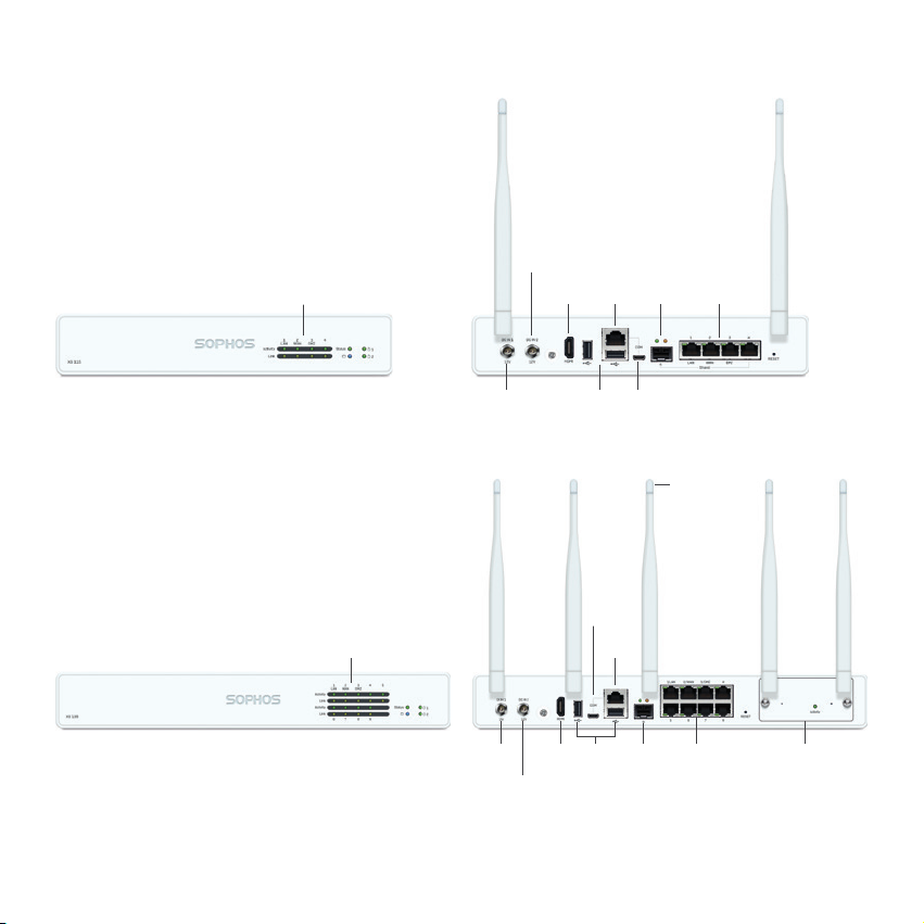
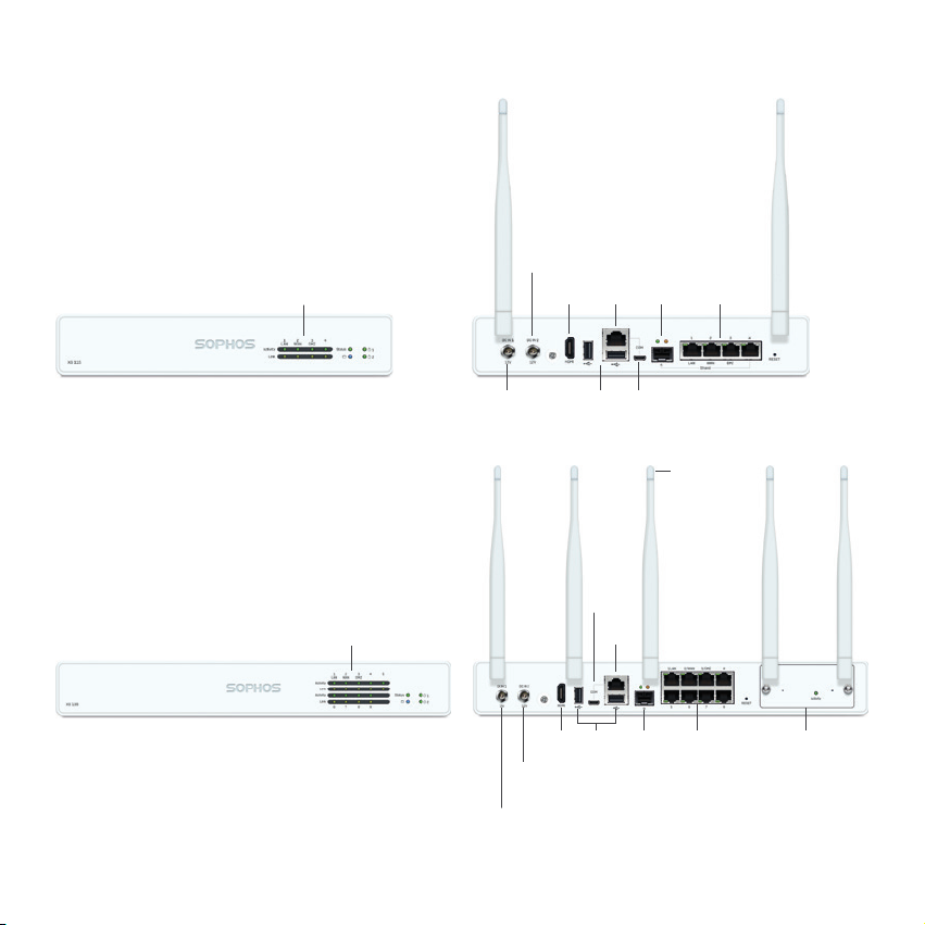
Device Images: Front and Back
XG 106(w)/115(w)
Status LEDs
(w-model has additional Wi-Fi LED)
*
2 x external antenna
(XG 106w and XG 115w only)
Connector for optional 2nd
redundant power supply
Power
Supply
HDMI
1 x
1 x COM
(RJ45)
2 x
USB 2.0
1 x GbE SFP
(shared)
1 x Micro
USB
4 x GbE
copper port
XG 125(w)/135(w)
Status LEDs
(w-model has additional Wi-Fi LED)
Power
1 x
Supply
HDMI
Connector for optional 2nd
redundant power supply
* The displayed front image is of the XG 115 and XG 135 device and the back is of the XG 115w and XG 135w.
1 x Micro
USB
1 x COM
(RJ45)
2 x
USB 2.0
1 x GbE
SFP
3 x external
antenna
(XG 125w and
XG 135w only)
8 x GbE
copper port
Expansion bay
(shown with optional
module incl. 2 antennas)
2 Quick Start Guide XG 115(w)/125(w)/135(w) Rev. 3, XG 106(w) Rev. 1
Page 4
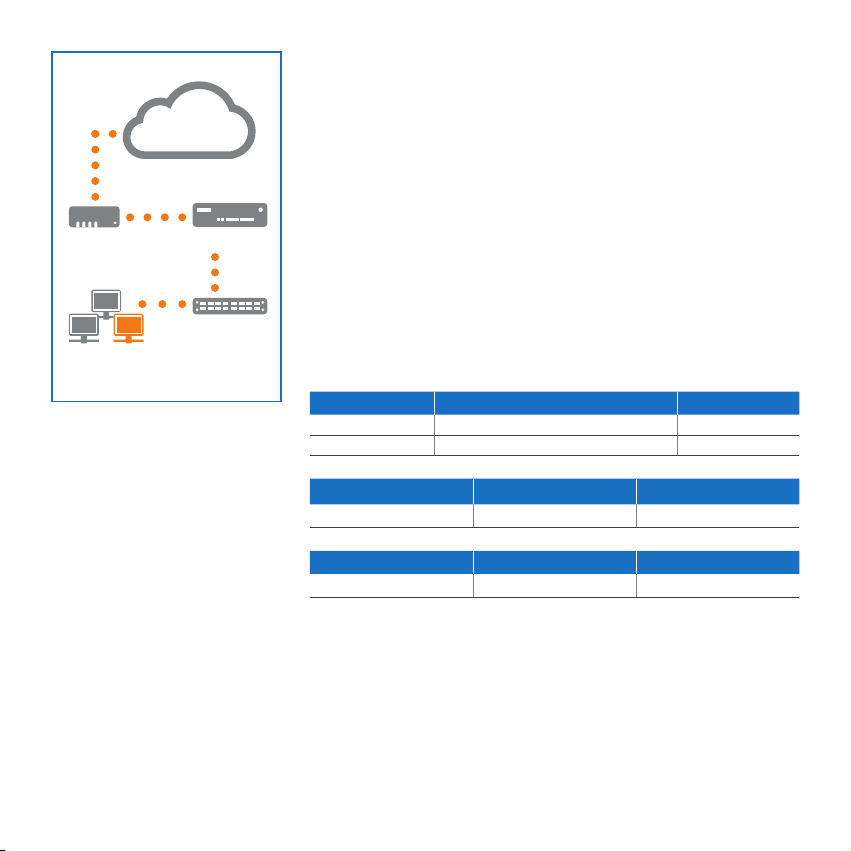
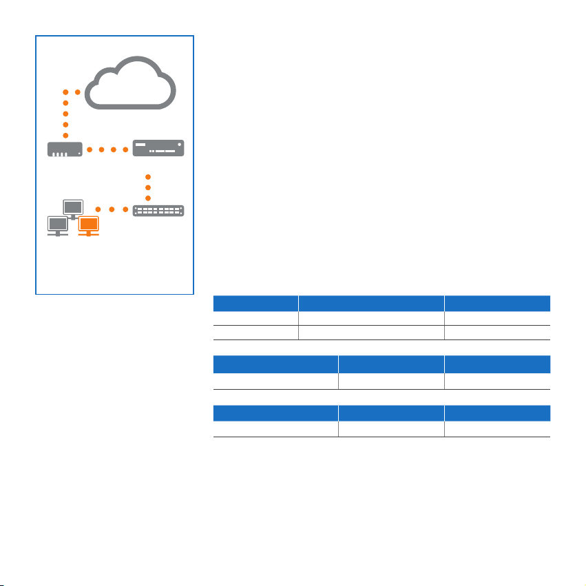
Port 2/
e.g.,
DSL modem
Internal network
admin client PC
WAN
Internet
XG Appliance
Port 1/
Switch
LAN
2. Mount & connect the device
Mount the antennas (for wireless models only)
Connect the provided antennas to the connectors on the back
of your appliance and align them in a vertical position.
Connect the ports to the internal and external networks
1. Connect the Port 1/LAN port via a hub or switch to the internal network. For this
purpose, use the RJ45 Ethernet cable provided. Note that your Administration PC
must also be connected to this network.
2. Connect Port 2/WAN to the external network. The connection to the WAN
depends on the type of Internet access.
Please note: On XG 106(w)/115(w) the SFP port is shared with RJ45 Ethernet Port
4 and takes precedence over the RJ45 port in case you connect cables to both ports
at the same time.
Note: For electromagnetic compatibility reasons, please only use shielded RJ45
Ethernet cables.
The XG devices are shipped with the following default settings:
Ethernet Port IP Address Zone
1 172.16.16.16/255.255.255.0 LAN
2 DHCP WAN
Admin Console Username Admin Console Password CLI Console Password
admin admin admin
Default Gateway DNS proxy DHCP service
DHCP Enabled Enabled
Mount the appliance to the rack
If you want to mount the device within a rack please use the optionally available
rackmount kit for this device.
Quick Start Guide XG 115(w)/125(w)/135(w) Rev. 3, XG 106(w) Rev. 1
3
Page 5

3. Power Up the Device
Connect the power adapter(s) and turn on the device
Connect the provided power adapter to connector 1 on the back of the device. In
order to increase redundancy you can connect an optionally available second power
adapter of the same type to power connector 2.
Turn the device on. The power switch is on the back of the device and is placed next
to the power connection.
During boot up the Status LED on the front will blink green. Once the device has
booted completely the Status LED will turn to solid green.
4. Connect your Administration PC
Administration PC connection properties:
Use the settings below to configure your (PC/Laptop) network interface:
Ì IP address: 172.16.16.2
Ì Netmask: Enter 255.255.255.0
Ì Default Gateway: Enter the IP address of the device’s
internal network card (Port 1/LAN): 172.16.16.16
Ì DNS Server: Enable this option and enter the IP address of
the internal network card (Port 1/LAN): 172.16.16.16
Connect your PC/Laptop to Port 1/LAN port of the device:
Start the browser and enter the management IP address of the device’s LAN port
that your PC is connected to: https://172.16.16.16:4444 (Port 1)
Login with the default details below:
Username: admin Password: admin
4
Quick Start Guide XG 115(w)/125(w)/135(w) Rev. 3, XG 106(w) Rev. 1
Page 6
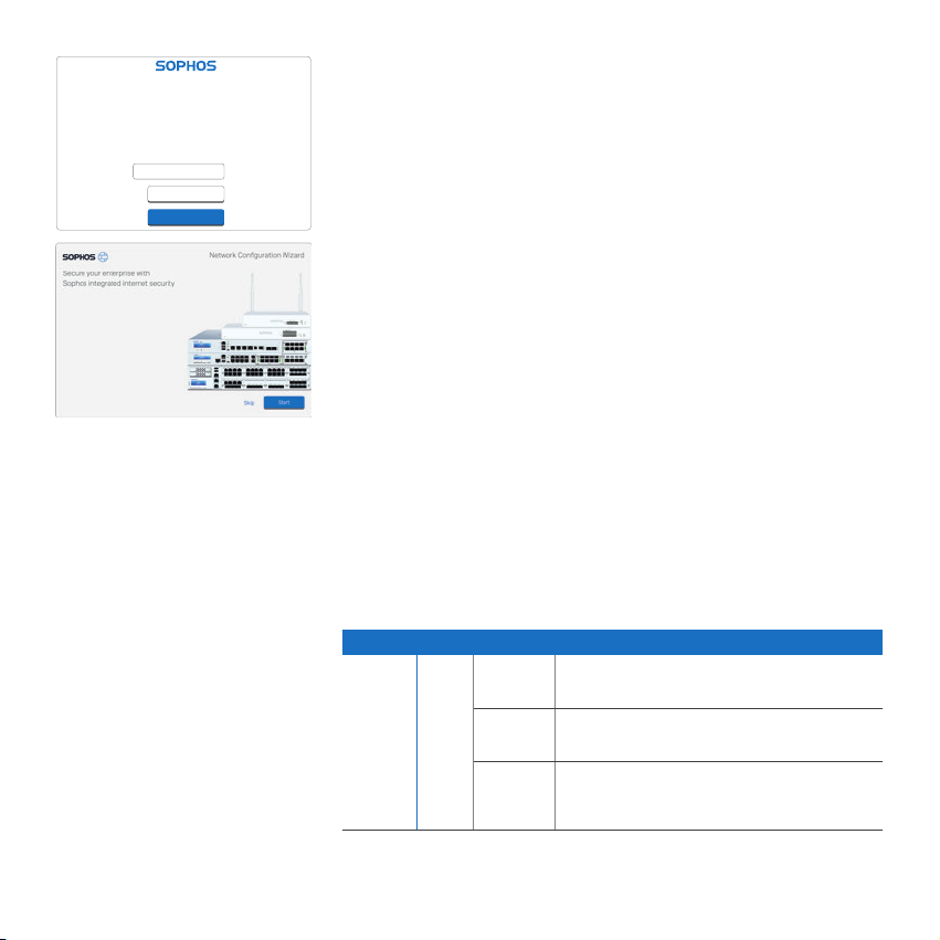
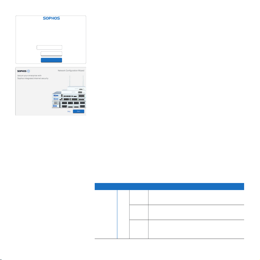
Device Management
Welcome
To your Sophos Device
To get started register your device below. Until you register you may only access
and edit settings in “Basic Setup” and your device will remain unactivated.
Serial Number
XXXXXXXXXXXXXXX
Basic Setup
Register Device
5. Setup the device
a) Register the Device
If you have not previously registered your device with your Sophos ID, you will see a
registration screen. The device requires Internet connectivity for it to be registered
with your Sophos ID. You can adjust the network settings of the device’s interfaces
by clicking “Basic Setup” so that the device can connect to the Internet.
After clicking “Register Device”, you are redirected to the Sophos.com. If you already
have a Sophos ID, enter your login credentials under “Sign in with your Sophos ID”.
If you are a new user, sign up for a Sophos ID by entering the details under “Create
Sophos ID”.
Click “Continue” to complete the registration process. Please wait while the process
completes – it will take a few seconds. After successful registration, you will see
a screen with the message, “Your device is now registered”. Please note that you
should proceed with the next step i.e. “Synchronize License” only after the device is
successfully registered.
b) Synchronize License
Click “Initiate License Synchronization” to fetch license information from Sophos
onto the device. After synchronization, you will see a screen with the message,
“Synchronization with server was successful”.
c) Start Network Configuration
After successful synchronization, choose “Click Here” on the “Welcome” screen
to start your initial device configuration. Use the Network Configuration Wizard
to select the deployment mode (Bridge/Gateway) for your device, change the
interface(s) IP addresses, default gateway, DNS settings and Date/Time Zone to
match your local network settings.
d) Device LED Status
LEDs on each RJ45 Ethernet connector
ACT/LNK
(Left LED)
Green Constantly 1. The Ethernet port is receiving power.
Flashing The adapter is sending or receiving network data.
Off 1. The adapter and switch are not receiving power.
2. Good connection between the Ethernet port
and hub.
The frequency of the flashes varies with the
amount of traffic.
2. No connection between both ends of network.
3. Network drivers have not been loaded or do not
function correctly.
Quick Start Guide XG 115(w)/125(w)/135(w) Rev. 3, XG 106(w) Rev. 1
5
Page 7
Speed
(Right
LED)
LEDs on SFP connector
ACT/LNK
(Left LED)
Amber On The Ethernet port is operating at 1,000 Mbps
Green On The Ethernet port is operating at 100 Mbps
Green Constantly 1. The SFP connector is receiving power.
Off The Ethernet port is operating at 10 Mbps
2. Good connection between the SFP connector
and hub.
Flashing The adapter is sending or receiving network data.
Off 1. The adapter and switch are not receiving power.
The frequency of the flashes varies with the amount
of traffic.
2. No connection between both ends of network.
3. Network drivers have not been loaded or do not
function correctly.
Speed
(Right
LED)
LEDs on front
Storage Blue Flashing SSD drive is being accessed
Status Green Constantly Normal operation
Wifi Green On Wifi is active
Power 1 Green Constantly Power adapter 1 in normal operation
Power 2 Green Constantly Power adapter 2 in normal operation
Amber On The Ethernet port is operating at 1,000 Mbps
Flashing Device is booting up or shutting down
Red Constantly SSD or boot failure
Flashing General error (please contat support)
Off Wifi is inactive
Red Constantly Power adapter 1 failed or disconnected
Red Constantly Power adapter 2 failed or disconnected
6. Support and Documentation
For more information and technical support, please visit www.sophos.com/en-us/
support or contact your local Sophos reseller.
6
Quick Start Guide XG 115(w)/125(w)/135(w) Rev. 3, XG 106(w) Rev. 1
Page 8
Für weitere Informationen zu Ihrer Appliance scannen Sie den QR-Code oder gehen Sie auf
www.sophos.com/get-started-xg
1. Vorbereitung
Herzlichen Glückwunsch zum Kauf dieser Sophos XG Appliance. Diese Kurzanleitung beschreibt schrittweise, wie Sie die
Appliance verbinden, und erläutert, wie Sie über Ihren Administrations-PC die webbasierte Admin Console öffnen. Über die Admin
Console können Sie jeden Aspekt der Appliance konfigurieren.
Bevor Sie beginnen, vergewissern Sie sich, dass Sie mit dem Internet verbunden sind und die Kontodaten vorliegen, die Sie von
Ihrem ISP erhalten haben.
Verpackungsinhalt
Diese Kurzanleitung und SicherheitshinweiseXG 106(w)/115(w)/125(w)/135(w)
XG 106w/115w – 2 Antennen,
XG 125w/135w – 3 Antennen
Kurzanleitung XG 115(w)/125(w)/135(w) Rev. 3, XG 106(w) Rev. 1
Micro USB-Kabel
RJ45 Ethernet-Kabel
Netzadapter (regionenspezifisch)
7
Page 9
Abbildungen der Appliance: Vorder- und Rückseite
XG 106(w)/115(w)
Status-LEDs
(w-Modell hat zusätzliche WiFi-LED)
*
Stromversorgung
2x externe Antenne
(nur XG106w und XG115w)
Anschluss für optionale
zweite redundante
Stromversorgung
1 x COM
1 x
(RJ45)
HDMI
2 x
USB 2.0
1 x GbE
SFP
(geteilt)
1 x MicroUSB
4 x
Kupferport
GbE
XG 125(w)/135(w)
1 x MicroUSB
HDMI
1 x COM
(RJ45)
2 x
1 x
USB 2.0
Status-LEDs
(w-Modell hat zusätzliche WiFi-LED)
Anschluss für optionale
zweite redundante
Stromversorgung
* Die Abbildung der Vorderseite bezieht sich auf die XG 115 und XG 135 Appliance und die der Rückseite auf die XG 115w und XG 135w.
8
Kurzanleitung XG 115(w)/125(w)/135(w) Rev. 3, XG 106(w) Rev. 1
Stromversorgung
1 x GbE
SFP
3x externe
Antenne
(nur XG125w
und XG135w)
8 x
Kupferport
GbE
Erweiterungsschacht
(abgebildet mit
optionalem Modul
einschl. 2Antennen)
Page 10
Port 2/
z.B.
DSL-Modem
Internes
Netzwerk
Administrations-
Client-PC
WAN
Internet
XG Appliance
Port 1/
Switch
LAN
2. Appliance montieren und verbinden
Antennen montieren (nur bei Wireless-Modellen)
Stecken Sie die mitgelieferten Antennen in die entsprechenden Anschlüsse auf der
Rückseite Ihrer Appliance ein und bringen Sie sie in eine vertikale Position.
Ports mit den internen und externen Netzwerken verbinden
1. Verbinden Sie Port 1/LAN-Port über einen Hub oder Switch mit dem internen
Netzwerk. Verwenden Sie hierzu das beiliegende RJ45 Ethernet-Kabel. Beachten
Sie, dass Ihr Administrations-PC ebenfalls mit diesem Netzwerk verbunden sein
muss.
2. Verbinden Sie Port 2/WAN mit dem externen Netzwerk. Die Verbindung zum
WAN hängt von der Art des Internetzugangs ab.
Bitte beachten Sie: Bei XG 106(w)/115(w) wird der SFP-Port mit RJ45 EthernetPort 4 geteilt und hat Vorrang vor dem RJ45-Port für den Fall, dass Sie Kabel mit
beiden Ports gleichzeitig verbinden.
Hinweis: Aus Gründen der elektromagnetischen Veträglichkeit verwenden Sie bitte
nur geschirmte RJ45 Ethernet-Kabel.
Für die XG Appliances sind werkseitig folgende
Standardeinstellungen festgelegt:
Ethernet-Port IP-Adresse Vertrauenswürdige Sites
1 172.16.16.16/255.255.255.0 LAN
2 DHCP WAN
Benutzername Admin Console Kennwort Admin Console Kennwort CLI Console
admin admin admin
Standard-Gateway DNS-Proxy DHCP-Dienst
DHCP Aktiviert Aktiviert
Appliance im Rack montieren
Wenn Sie die Appliance in einem Rack montieren möchten, verwenden Sie das für
dieses Gerät optional erhältliche Rackmontage-Kit.
Kurzanleitung XG 115(w)/125(w)/135(w) Rev. 3, XG 106(w) Rev. 1
9
Page 11

3. Appliance einschalten
Netzadapter anschließen und Appliance einschalten
Verbinden Sie den mitgelieferten Netzadapter mit dem Anschluss 1 auf der
Rückseite der Appliance. Um die Redundanz zu erhöhen, können Sie einen optional
erhältlichen zweiten Netzadapter desselben Typs mit Netzanschluss 2 verbinden.
Schalten Sie die Appliance ein. Der Netzschalter befindet sich auf der Rückseite der
Appliance neben dem Netzanschluss.
Beim Hochfahren blinkt die Status-LED auf der Vorderseite grün. Sobald die
Appliance hochgefahren ist, leuchtet die Status-LED grün.
4. Administrations-PC verbinden
Verbindungseigenschaften des Administrations-PC:
Verwenden Sie die nachfolgenden Einstellungen für die Konfiguration Ihrer (PC-/
Notebook-)Netzwerkschnittstelle:
Ì IP-Adresse: 172.16.16.2
Ì Netzmaske: 255.255.255.0
Ì Standardgateway: Geben Sie die IP-Adresse der internen
Netzwerkkarte des Geräts ein (Port 1/LAN): 172.16.16.16
Ì DNS-Server: Aktivieren Sie diese Option und geben Sie die IP-Adresse
der internen Netzwerkkarte ein (Port 1/LAN): 172.16.16.16
Verbinden Sie Ihren PC/Ihr Notebook mit dem Port 1/LAN-Port der
Appliance:
Öffnen Sie den Browser und geben Sie die Verwaltungs-IP-Adresse des LAN-Ports
der Appliance ein, mit dem Ihr PC verbunden ist: https://172.16.16.16:4444 (Port 1)
Melden Sie sich mit den nachfolgenden Standarddaten an:
Benutzername: admin Kennwort: admin
10
Kurzanleitung XG 115(w)/125(w)/135(w) Rev. 3, XG 106(w) Rev. 1
Page 12
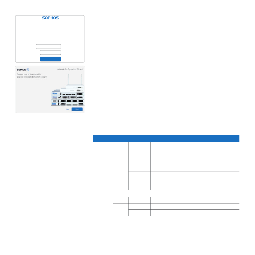
Device Management
Welcome
To your Sophos Device
To get started register your device below. Until you register you may only access
and edit settings in “Basic Setup” and your device will remain unactivated.
Serial Number
XXXXXXXXXXXXXXX
Basic Setup
Register Device
5. Gerät konfigurieren
a) Das Gerät registrieren
Falls Sie Ihre Appliance noch nicht unter Ihrer Sophos ID registriert haben, wird
ein Bildschirm zur Registrierung angezeigt. Für die Registrierung unter Ihrer
Sophos ID muss die Appliance mit dem Internet verbunden sein. Sie können die
Netzwerkeinstellungen der Schnittstellen der Appliance anpassen. Klicken Sie dazu
auf „Grundkonfiguration“, damit sich die Appliance mit dem Internet verbinden kann.
Wenn Sie auf „Appliance registrieren“ klicken, werden Sie zu Sophos.com
weitergeleitet. Falls Sie bereits eine Sophos ID besitzen, geben Sie Ihre
Anmeldedaten unter „Mit Ihrer Sophos ID anmelden“ ein. Als neuer Benutzer müssen
Sie sich für eine Sophos ID registrieren, indem Sie die erforderlichen Angaben unter
„Sophos ID erstellen“ eintragen.
Klicken Sie auf „Weiter“, um die Registrierung abzuschließen. Bitte warten Sie einige
Sekunden, bis der Vorgang abgeschlossen ist. Nach der erfolgreichen Registrierung
wird ein Bildschirm mit der Meldung „Ihre Appliance ist jetzt registriert“ angezeigt.
Beachten Sie, dass Sie mit dem nächsten Schritt – „Lizenz synchronisieren“ – erst
nach erfolgreicher Registrierung der Appliance fortfahren sollten.
b) Lizenz synchronisieren
Klicken Sie auf „Lizenzsynchronisierung starten“, um Lizenzinformationen von
Sophos auf die Appliance abzurufen. Nach der Synchronisierung wird ein Bildschirm
mit der Meldung „Synchronisierung mit Server war erfolgreich“ angezeigt.
c) Netzwerkkonfiguration starten
Klicken Sie nach der erfolgreichen Synchronisierung auf dem Begrüßungsbildschirm
auf „Hier klicken“, um die Erstkonfiguration der Appliance zu starten. Verwenden
Sie den Assistenten für die Netzwerkkonfiguration, um den Bereitstellungsmodus
(Bridge/Gateway) für Ihre Appliance auszuwählen und die IP-Adresse(n) der
Schnittstelle(n), das Standard-Gateway, die DNS-Einstellungen und die Datums-/
Zeitzone entsprechend Ihren lokalen Netzwerkeinstellungen zu ändern.
d) LED-Statusanzeigen der Appliance
LEDs am jeweiligen RJ45 Ethernet-Anschluss
ACT/LNK
(Linke LED)
Grün Leuchtet 1. Der Ethernet-Port wird mit Strom versorgt.
Blinkt Der Adapter sendet oder empfängt Netzwerkdaten.
Aus 1. Adapter und Switch werden nicht mit Strom versorgt.
2. Verbindung zwischen Ethernet-Port und Hub
funktioniert.
Die Blinkfrequenz hängt von der Menge des
Datenverkehrs ab.
2. Keine Verbindung zwischen beiden Netzwerkenden.
3. Netzwerktreiber wurden nicht geladen oder
funktionieren nicht richtig.
Kurzanleitung XG 115(w)/125(w)/135(w) Rev. 3, XG 106(w) Rev. 1
11
Page 13

Geschwindigkeit
(Rechte LED)
LEDs am SFP-Anschluss
ACT/LNK
(Linke LED)
Gelb Ein Der Ethernet-Port arbeitet mit 1.000 Mbps.
Grün Ein Der Ethernet-Port arbeitet mit 100 Mbps.
Grün Leuchtet 1. Der SFP-Anschluss wird mit Strom versorgt.
Aus Der Ethernet-Port arbeitet mit 10 Mbps.
2. Verbindung zwischen SFP-Anschluss und Hub
funktioniert.
Blinkt Der Adapter sendet oder empfängt Netzwerkdaten.
Aus 1. Adapter und Switch werden nicht mit Strom
Die Blinkfrequenz hängt von der Menge des
Datenverkehrs ab.
versorgt.
2. Keine Verbindung zwischen beiden Netzwerkenden.
3. Netzwerktreiber wurden nicht geladen oder
funktionieren nicht richtig.
Geschwindigkeit
(Rechte LED)
LEDs auf der Vorderseite
Speicher Blau Blinkt Zugriff auf SSD-Laufwerk
Status Grün Leuchtet Normaler Betrieb
WLAN Grün Ein WLAN ist aktiv
Power 1 Grün Leuchtet Netzadapter 1 funktioniert normal
Power 2 Grün Leuchtet Netzadapter 2 funktioniert normal
Gelb Ein Der Ethernet-Port arbeitet mit 1.000 Mbps.
Blinkt Appliance fährt hoch oder herunter
Rot Leuchtet Problem mit SSD oder beim Hochfahren
Blinkt Allgemeiner Fehler (bitte Support kontaktieren)
Aus WLAN ist inaktiv
Rot Leuchtet Netzadapter 1 funktioniert nicht oder ist nicht
Rot Leuchtet Netzadapter 2 funktioniert nicht oder ist nicht
verbunden
verbunden
6. Support und Dokumentation
Für weitere Informationen und technischen Support gehen Sie auf die Website
www.sophos.com/de-de/support oder wenden Sie sich an Ihren Sophos
Vertriebspartner vor Ort.
12 Kurzanleitung XG 115(w)/125(w)/135(w) Rev. 3, XG 106(w) Rev. 1
Page 14

デバイスの詳細については、 QR コードを読み取るか
www.sophos.com/get-started-xg をご 覧ください 。
1.はじめに
Sophos XG デバイスをご購入いただきありがとうございます。このクイック スタート ガイドでは、デバイスの接続方法と、お客様の管理 PC
から Web ベースの管理コンソールを開く方法について説明しています。管理コンソールでは、デバイスに関するあらゆる設定が可能です。
作業を始める前に、有効なインターネット接続と ISP から提供されたアカウント情報があることを確認してください。
製品に含まれる内容
XG 106(w)/115(w)/125(w)/135(w)
XG 106w/115w - アンテナ (2本)、
XG 125w/135w - アンテナ (3本)
クイッ ク スタート ガイド XG 115(w)/125(w)/135(w) Rev. 3, XG 106(w) Rev. 1
本 書 クイック スタ ート ガ イドお よび セ キュリテ
ィノー ト
RJ45 イーサネットケーブル
電源アダプタ (地域対応)
Micro USB ケーブル
13
Page 15

デバイスの画像: 前面および背面
XG 106(w)/115(w)
テータス表示 LED
(w モデルは Wi-Fi 接続表示 LED 搭載)
*
外部アンテナ x 2
(XG 106w および XG 115w のみ)
オプ ション の冗
長電源接続口
HDMI
1 x
1 x COM
(RJ45)
GbE SFP
x 1 (共有)
GbE copper
ポート x 4
電源
XG 125(w)/135(w)
テータス表示 LED
(w モデルは Wi-Fi 接続表示 LED 搭載)
電源
HDMI
x 1
オプションの冗長電源接続口
* 表示されている前面イメージは XG 115 および XG 135 デバイスで、背面イメージ XG 115w および XG 135w です。
14
クイッ ク スタート ガイド XG 115(w)/125(w)/135(w) Rev. 3, XG 106(w) Rev. 1
USB 2.0 x 2 Micro
Micro
USB x 1
(RJ45)
USB 2.0
x 2
COM
x 1
USB x 1
GbE
SFP
x 1
外部アンテナ x 3
(XG 125w および
XG 135w のみ)
GbE copper
ポート x 8
拡張ベイ
(ここではアンテナ 2本
を含 む オプ ション のモ
ジュールを搭載)
Page 16

Port 2/
例:
DSL モデム
社 内 ネ ットワ ー ク
管 理 クラ イア ン
ト PC
イ ンタ ー ネット
WAN
XG アプライアンス
1/LAN
スイッ チ
Port
2.デバイスの取り付けおよび接続
アンテナの取り付け (ワイヤレスモデルの み)
同梱されているアンテナをアプライアンスの背面のコネクタに接続して、垂直方向に立て
ます。
ポートを内部および外部ネットワークに接続する
1. ハブまたはスイッチ経由で Port 1/LAN ポートを内部ネットワークに接続します。この接
続には、本製品に付属の RJ45 イーサネットケーブルを使用してください。また、管理用
PC も、このネットワークに接続してください。
2. Port 2/WAN ポートを外部ネットワークに接続します。WAN への接続はイン
ターネットアクセスの種類 によって異なります。
注: XG 106(w)/115(w) では、SFP ポートは RJ45 イーサネットポート 4 と共有で使用され、
ケーブルを両方のポートに同時に接続した場合には RJ45 ポートよりも優先されます。
注:電磁両立性の理由から、シールドされたRJ45イーサネットケーブルのみを使用してく
ださい 。
XG デバイスは以下のデフォルト設定で提供されます。
イ ー サネット ポ ー ト IP アドレス ゾーン
1 172.16.16.16/255.255.255.0 LAN
2 DHCP WAN
管理コンソールのユーザー名 管理コンソールのパスワード CLI コンソールのパスワード
admin admin admin
デフォルトゲ ートウェイ DNS プロキシ DHCP サービス
DHCP 有効 有効
アプライアンスをラックに取り付ける
デバイスをラック内に取り付ける場合、このデバイスにオプションで提 供される
ラック 取り付 け 用 のキットを 使用してください 。
クイッ ク スタート ガイド XG 115(w)/125(w)/135(w) Rev. 3, XG 106(w) Rev. 1
15
Page 17

3.デバイスの電源を入れる
電源アダプタを接続してデバイスに電源を入れる
同梱されている電源アダプタをデバイスの背面のコネクタ 1 に接続します。冗長性を高
めるためには、オプションで利用可能な同じ種類の電源アダプタを電源コネクタ 2 に接
続で きます。
デバイスの電源をオンにします。電源スイッチはデバイス背面の電源接続口の横にあり
ま す 。
起動中には前面のステータス LED が緑色に点滅します。デバイスの起動が完了するとス
テータス LED は緑色に点灯します。
4.管理 PC を接続する
管理 PC 接続プロパティ:
以下の設定を使用してお客様の PC / ノート PC のネットワークインターフェースを設定
します。
Ì IP アドレス: 172.16.16.2
Ì ネットマスク: 255.255.255.0 を入力
Ì デフォルトゲ ートウェイ: デバイス の内 部 ネットワ ーク カードの
IP アドレス (Port 1/LAN): 172.16.16.16 を入力
Ì DNS サーバー: このオプションを有効にし、内部ネットワークカードの
IP アドレス (Port 1/LAN): 172.16.16.16 を入力
PC / ノート PC をデバイスの Port 1/LAN ポートに接続する
ブラウザを起動し、お客様の PC が接続しているデバイスの LAN ポートの管理 IP アドレ
ス: https://172.16.16.16:4444 (Port 1) を入 力します。
以 下 の デ フ ォ ル ト の 値 で ロ グ イ ン し ま す 。
ユーザー名:admin パスワード:admin
16
クイッ ク スタート ガイド XG 115(w)/125(w)/135(w) Rev. 3, XG 106(w) Rev. 1
Page 18

Device Management
Welcome
To your Sophos Device
To get started register your device below. Until you register you may only access
and edit settings in “Basic Setup” and your device will remain unactivated.
Serial Number
XXXXXXXXXXXXXXX
Basic Setup
Register Device
5.デバイスの設定
a) デバイスの登録
以前に Sophos ID でデバイスを登録していない場合は、登録画面が表示されま
す。Sophos ID で登録するためにデバイスにはインターネット接続が必要です。デバイスが
インターネットに接続できるように「基本設定」をクリックしてデバイスのインターフェース
のネットワーク設定を調整できます。
「デバイスの登録」をクリックすると Sophos.com にリダイレクトされます。
Sophos ID を既にお持ちの場合、「Sophos ID を使ってログインしてください。」の下でログ
インアカウント情報を入力しますお客様が新規ユーザーの場合、「Sophos ID の作成」の
下で詳細情報を入力して Sophos ID を作成してください。
「続行」をクリックして登録処理を完了します。処理が完了するまで数秒間待ちます。登録
で正常に完了すると「デバイスは登録されました」というメッセージが画面に表示されま
す。デバイスが登録を正常に完了した場合にのみ、次の手順として「ライセンスの同期」を
実 行できます。
b) ライセンスの同期
「ライセンスの同期の開始」をクリックしてサーバーのライセンス情報をデバイスと同期さ
せます。同期が完了すると「サーバーとの同期が成功しました」という内容のメッセージが
画面に表示されます。
c) ネットワーク設定の開始
同期が正常に完了した場合、「ようこそ」の画面上の「こちらをクリック」を選択すると初期
のデバイス設定を開始できるようになります。ネットワーク設定ウィザードを使用してデバ
イスの導入モード (ブリッジ / ゲートウェイ) を選択し、お客様のネットワーク設定に一致し
たインターフェース IP アドレス、デフォルトゲートウェイ、DNS 設定、日付 / 時刻のゾーン
を 変 更してく ださ い 。
d) デバイスの LED のステータス
各 RJ45 イーサネットコネクタの LED
ACT/LNK
(左側の
LED)
緑 点灯 1. イーサネットが電源供給を受けています。
2. イーサ ネットポ ートとハブの 間の 接続 が 正常 です。
点滅 アダプタがネットワークデータを送信、または受信中です。
トラフィック量によって点滅の頻度は変わってきます。
消灯 1. アダプタおよびスイッチが電源供給を
受 け 取ってい ませ ん 。
2. ネットワークの 両端に対して接 続がありません。
3. ネットワークドライバが読み込まれていない、または
適切に機能していません。
クイッ ク スタート ガイド XG 115(w)/125(w)/135(w) Rev. 3, XG 106(w) Rev. 1
17
Page 19

速度
(右側の
LED)
SFP コネクタの LED
ACT/LNK
(左の LED)
黄 点灯 イーサネットポートが 1,000 Mbps で作動しています。
緑 点灯 イーサネットポートが 100 Mbps で作動しています。
緑 点灯 1. SFP コネクタが電源供給を受けています。
消灯 イーサネットポートが 10 Mbps で作動しています。
2. SFP コネクタとハブが正常に接続しています。
点滅 アダプタがネットワークデータを送信、または受信中です。
トラフィック量によって点滅の頻度は変わってきます。
消灯 1. アダプタおよびスイッチが電源供給を受け取っていません。
2. ネットワークの両 端に対して接 続がありません。
3. ネットワークドライバが読み込まれていない、または
適切に機能していません。
速度 (右
の LED)
前面の LED
ストレ ー ジ
状態
Wi-Fi
電源 1
電源 2
黄 点灯 イーサネットポートが 1,000 Mbps で作動しています。
青 点滅 SSD ドライブが使用されています。
緑 点灯 通常に作動中
点滅 デバイスが起動中またはシャットダウン中
赤 点灯 SSD または起動の失敗
点滅 一般的なエラー (サポートにお問い合わせください)
緑 点灯 Wi-Fi が有効
消灯 Wi-Fi が無効
緑 点灯 電源アダプタ 1 が通常に作動中
赤 点灯 電源アダプタ 1 が失敗または切断
緑 点灯 電源アダプタ 2 が通常に作動中
赤 点灯 電源アダプタ 2 が失敗または切断
6. サ ポートおよびドキュメント
詳細情報およびテクニカルサポートについては、www.sophos.com/ja-jp/support また
はソフォス営業部にお問い合わせください。
18
クイッ ク スタート ガイド XG 115(w)/125(w)/135(w) Rev. 3, XG 106(w) Rev. 1
Page 20

有关设备的详细信息,请扫描 QR 码或访问
www.sophos.com/get-started-xg
1.部署前
恭喜您购买了Sophos XG设备。本快速入门指南简要描述了设备的连接步骤,并解释了如何从您的管理计算机打开基于Web的管理控
制台。管理控制台让您可以配置设备的各个方面。
开始前,请确认您有有效的Internet连接,并确保您的ISP所提供的帐户信息可用。
包装清单
XG 106(w)/115(w)/125(w)/135(w)
XG 106w/115w - 2 根天线;
XG 125w/135w - 3 根天线
快速入门指南 XG 115(w)/125(w)/135(w) Rev. 3, XG 106(w) Rev. 1
快速入门指南和安全说明
电源适配器 (特定于区域)
Micro USB 电缆
RJ45网线
19
Page 21

设备图:正面和背面
XG 106(w)/115(w)
*
状态指示灯
(w 型有额外的 Wi-Fi 指示灯)
可选的第 2 冗余电源连接器
HDMI
电源供给
2 x 外接天线
(仅就XG106w及XG115w而言)
1 x 串
行通讯
端口
(RJ45)
2 x
USB 2.0
1 x GbE SFP
(共用)
1 x Micro
USB
1 x
4 x GbE
铜制端口
XG 125(w)/135(w)
状态指示灯
(w 型有额外的 Wi-Fi 指示灯)
* 显示的是 XG 115 和 XG 135 设备的前面图以及 XG 115w 和 XG 135w 的后面图。
20
3 x 外接天线
仅指XG125w及
XG135w)
1 x
Micro
USB
1 x 串行
通讯端口
(RJ45)
电源
1 x
供给
HDMI
可选的第 2 冗余电源连接器
2 x
USB 2.0
1 x GbE
SFP
8 x GbE
copper端口
扩展机架
(显示了包括 2 根天线的
可选模块)
快速入门指南 XG 115(w)/125(w)/135(w) Rev. 3, XG 106(w) Rev. 1
Page 22

端口 2/WAN
例 如 ,
DSL调制解调器
内部网络 管理客
户端PC
内部
XG设备
1/LAN
开关
端口
2.安装并连接设备
安装天线 (仅适用于无线型号)
将提供的天线连接到您设备后面的连接器上,并将它们在垂直位置对齐。
将端口连接到内部网络和外部网络
1. 将端口 1/LAN 端口通过集线器或交换机连接到内部网络。为此,请使用提供的RJ45
以太网线缆。请注意,您的管理计算机也必须连接到该网络。
2. 将端口 2/WAN 端口连接到外部网络。WAN的连接方式取决于Internet访问的类型。
请注意: 在 XG 106(w)/115(w) 上,SFP 端口共用 RJ45 以太网端口 4,如果同时将电缆连
接到两个端口,则优先级高于 RJ45 端口。
注意:出于电磁兼容性原因,请仅使用屏蔽RJ45乙太网络电缆
XG设备附带以下默认设置:
以太网端口 IP地址 区域
1. 172.16.16.16/255.255.255.0 LAN
2. DHCP WAN
管理控制台的用户名 管理控制台的密码 CLI控制台密码
admin admin admin
默认网关 DNS代理 DHCP服务
DHCP 启用 启用
将设备安装在机架上
如果要将设备安装到机架内,请使用为此设备提供的可选配机架安装工具。
快速入门指南 XG 115(w)/125(w)/135(w) Rev. 3, XG 106(w) Rev. 1
21
Page 23

3.开启设备电源
连接电源适配器并开启设备
将提供的电源适配器连接到设备后侧的连接器 1。为提高冗余性,可将相同类型的可选
备用电源适配器连接到电源连接器 2。
开启设备。电源开关位于设备后面,在电源接头旁边。
启动时,前面的状态 LED 将会闪烁绿色。设备完全启动后,状态 LED 将变为稳定的绿色。
4.连接您的管理计算机
管理计算机连接属性:
使用以下设置配置您的(PC/笔记本)网络接口:
Ì IP 地址:172.16.16.2
Ì 子网掩码:输入 255.255.255.0
Ì 默认网关:输入设备的内部网卡的 IP 地址(端口 1/LAN):172.16.16.16
Ì DNS 服务器:启用此选项,并输入内部网卡的 IP 地址(端口 1/LAN):172.16.16.16
将您的 PC/笔记本连接到设备的端口 1/LAN 端口:
启动浏览器,并输入您的计算机连接的设备 LAN 端口的管理 IP 地
址:https://172.16.16.16:4444 (端口 1)
使用以下默认的详细信息登录:
用户名: admin 密码: admin
22
快速入门指南 XG 115(w)/125(w)/135(w) Rev. 3, XG 106(w) Rev. 1
Page 24

Device Management
Welcome
To your Sophos Device
To get started register your device below. Until you register you may only access
and edit settings in “Basic Setup” and your device will remain unactivated.
Serial Number
XXXXXXXXXXXXXXX
Basic Setup
Register Device
5.安装设备
a)注册设备
如果之前没有使用 Sophos ID 注册您的设备,您将会看到注册屏幕。要使用 Sophos ID
注册设备,它必须连接到 Internet。通过单击“基本设置”,可以调整设备接口的网络设
置,使设备可以连接到Internet。
单击“注册设备”后,将跳转到 Sophos.com。如果您已经有 Sophos ID,请在“使用您的
Sophos ID 登录”下输入您的登录凭据。如果您是新用户,请在“创建 Sophos ID”下输入
详细信息,注册 Sophos ID。
单击“继续”完成注册。请等待该过程处理完成,它可能需要一会儿。成功注册后,将会看
到一条屏幕消息:“您的设备现在已注册”。请注意,只应在设备成功注册后,才继续进行
下一步,即“同步许可证”。
b)同步许可证
单击“启动许可证同步”,将许可证信息从Sophos提取到设备上。同步后,将会看到一条
屏幕消息:“服务器同步已成功”。
c)启动网络配置
成功同步后,在“欢迎”屏幕上选择“单击此处”,启动初次设备配置。使用“网络配置向导”
选择您设备的部署模式(网桥/网关),更改接口的IP地址、默认网关、DNS设置以及日期/
时区,以匹配您的本地网络设置。
d)设备LED状态
每个 RJ45 以太网连接器上的 LED 指示灯
活动/链接
(左侧
LED)
绿色 持续 1. 以太网端口正在接收电源。
闪烁 适配器正在发送或接收网络数据。
关 1. 适配器和开关未接收电源。
2. 以太网端口和集线器连接良好。
闪烁的频率跟随流量总量变化。
2. 网络两端没有连接。
3. 网络驱动程序尚未加载或无法正确工作。
速度
(右侧
LED)
琥珀色 开启 以太网端口以 1,000 Mbps 的速率传输数据
绿色 开启 以太网端口以 100 Mbps 的速率传输数据
关 以太网端口以 10 Mbps 的速率传输数据
快速入门指南 XG 115(w)/125(w)/135(w) Rev. 3, XG 106(w) Rev. 124快速入门指南 XG 115(w)/125(w)/135(w) Rev. 3, XG 106(w) Rev. 1
23
Page 25

SFP 连接器的 LED 指示灯
活动/链接
(左侧 LED)
绿色 持续 1. SFP 连接器正在接收电源。
2. SFP 连接器和集线器连接良好。
闪烁 适配器正在发送或接收网络数据。
闪烁的频率跟随流量总量变化。
关 1. 适配器和开关未接收电源。
2. 网络两端没有连接。
3. 网络驱动程序尚未加载或无法正确工作。
速度 (右侧
LED)
前面的 LED
存储
狀態
WiFi
电源 1
电源 2
琥珀色 开启 以太网端口以 1,000 Mbps 的速率传输数据
蓝色 闪烁 正在访问固态硬盘
绿色 持续 正常运行
闪烁 设备正在启动或关机
红色 持续 固态硬盘或启动故障
闪烁 一般错误 (请联系支持人员)
绿色 开启 无线网有效的
关 无线网无效的
绿色 持续 电源适配器 1 正常运行
红色 持续 电源适配器 1 故障或未连接
绿色 持续 电源适配器 2 正常运行
红色 持续 电源适配器 2 故障或未连接
6.支持和文档
有关详细信息和技术支持,请访问www.sophos.com/zh-cn/support或联系您的本地
Sophos分销商。
Page 26

如欲了解更多關於您的設備,請掃瞄二維碼或造訪
www.sophos.com/get-started-xg
1.在部署前
恭喜您購買 Sophos XG 裝置。本《快速入門指南》簡短描述了連接裝置的步驟,並說明如何從管理電腦開啟網頁式 Admin 主控
台。Admin 主控台可讓您設定裝置的各個層面。
在開始之前,請確認您可以連線至網際網路,並確定您擁有 ISP 提供的帳戶資訊。
這盒的內容
XG 106(w)/115(w)/125(w)/135(w)
XG 106w/115w - 2 個天線;
XG 125w/135w - 3個天線
快速入門指南 XG 115(w)/125(w)/135(w) Rev. 3, XG 106(w) Rev. 1
本快速入門指南和安全注意事項
RJ45 乙太網路纜線
變壓器 (依地區而有所不同)
Micro USB 纜線
25
Page 27

裝置圖像:正面和背面
XG 106(w)/115(w)
*
狀態 LED
(w 機型有額外的 Wi-Fi LED)
選用第 2 個備援電源供應器
的連接器
1 x
HDMI
電源供
應器
2 x 外部天線
(僅限 XG 106w 和 XG 115w)
1 x COM
1 x GbE SFP
(RJ45)
(共用)
2 x
1 x Micro
USB 2.0
USB
4 x GbE 銅
軸埠
XG 125(w)/135(w)
狀態 LED
(w 機型有額外的 Wi-Fi LED)
* 顯示的正面圖像屬於 SG 115 和 SG 135 裝置,而背面圖像是屬於 XG 115w和XG 135w。
26
3 x 外部天線
(僅限 XG 125w 和
XG 135w)
1 x Micro
USB
1 x COM
(RJ45)
電源供
1 x
應器
HDMI
選用第 2 個備援電源供應器
的連接器
2 x
USB 2.0
1 x GbE
SFP
8 x GbE 銅
軸埠
擴充槽
(與選用模組一起顯示,包
含 2 個天線)
快速入門指南 XG 115(w)/125(w)/135(w) Rev. 3, XG 106(w) Rev. 1
Page 28

連接埠 2/
例 如,
DSL 數據機
內部網路 管理員用
戶端電腦
WAN
網際網路
XG 設備
連接埠
1/WAN
交換器
2.掛載與連接裝置
裝上天線(只適用於無線型號)
把附上的天線接上您器件的背面連接口,
並把它們垂直對準。
將連接埠連接至內/外部網路
1. 將連接埠 1/LAN 埠透過集線器或交換器連接到內部網路。為此,請使用所提供的
RJ45 乙太網路纜線。請注意,管理電腦也必須連線到這個網路。
2. 將連接埠 2/WAN 連接到外部網路。與 WAN 的連線取決於網際網路存取的類型。
请注意:在 SG 106(w)/115(w) 上,SFP 埠與 RJ45 乙太網路連接埠 4 共用,如果您同時在
兩個連接埠連接纜線,則 RJ45 埠優先使用。
注 意:出於電磁兼容性原因,請使用遮蔽型RJ45乙太網路線。
XG 裝置出貨時隨附下列預設設定:
乙太網路連接埠 IP 位址 區域
1 172.16.16.16/255.255.255.0 LAN
2 DHCP WAN
Admin 主控台使用者名稱 Admin 主控台密碼 CLI 主控台密碼
admin admin admin
預設閘道 DNS Proxy DHCP 服務
DHCP 啟用 啟用
將設備掛載到機架
如果您想要在機架內掛載裝置,請使用此裝置可選用的機架掛載套件。
快速入門指南 XG 115(w)/125(w)/135(w) Rev. 3, XG 106(w) Rev. 1
27
Page 29

3.開啟裝置電源
連接變壓器,然後開啟裝置
將提供的變壓器連接至裝置背面的接頭 1。若要增加備援,您可以將相同類型的另一個
選用變壓器連接至電源接頭 2。
開啟裝置。電源開關位於裝置背面,電源連線的旁邊。
在開機期間,正面的狀態 LED 將會閃綠燈。一旦裝置完全開機之後,狀態 LED 將會變成
恆亮綠燈。
4.連接管理電腦
管理電腦連線內容:
使用以下設定來設定您的 (電腦/筆記型電腦) 網路介面:
Ì IP 位址:172.16.16.2
Ì 網路遮罩:輸入 255.255.255.0
Ì 預設閘道:輸入裝置內部網路卡的 IP 位址 (連接埠 1/LAN):172.16.16.16
Ì DNS 伺服器:啟用此選項,然後輸入內部網路卡
的 IP 位址 (連接埠 1/LAN):172.16.16.16
將您的電腦/筆記型電腦連接至裝置的連接埠 1/LAN 埠:
啟動瀏覽器,然後輸入與您電腦連接之裝置 LAN 埠的管理 IP 位
址:https://172.16.16.16:4444 (連接埠 1)
使用以下的預設詳細資料登入:
使用者名稱: admin 密 碼: admin
28
快速入門指南 XG 115(w)/125(w)/135(w) Rev. 3, XG 106(w) Rev. 1
Page 30
Device Management
Welcome
To your Sophos Device
To get started register your device below. Until you register you may only access
and edit settings in “Basic Setup” and your device will remain unactivated.
Serial Number
XXXXXXXXXXXXXXX
Basic Setup
Register Device
5.設定裝置
a) 註冊裝置
如果您先前尚未使用 Sophos ID 註冊您的裝置,您將會看到一個註冊畫面。此裝置需要
有網際網路連線,才能使用您的 Sophos ID 註冊該裝置。您可以按一下「基本設定」來調
整裝置介面的網路設定,讓裝置可以連線到網際網路。
按一下「註冊裝置」之後,系統會將您重新導向至 Sophos.com。如果您已經有 Sophos
ID,請在「使用您的 Sophos ID 登入」底下,輸入您的登入認證。如果您是新使用者,請在「
建立 Sophos ID」底下輸入詳細資料,藉此註冊一個 Sophos ID。
按一下「繼續」可完成註冊程序。請等待程序完成 (將需要幾秒鐘的時間)。成功註冊之後,
您將會看到一個畫面,顯示「您的裝置現在已完成註冊」的訊息。請注意,只有在成功註冊
裝置之後,才能繼續下一個步驟,亦即「同步授權」。
b) 同步授權
按一下「起始授權同步」可將授權資訊從 Sophos 擷取到裝置上。同步之後,您將會看到
一個畫面,顯示「與伺服器同步成功」的訊息。
c) 開始網路設定
成功同步之後,在「歡迎」畫面上選擇「按一下這裡」,即可開始初始網路設定。使用「網路
設定精靈」選取您裝置的部署模式 (橋接/閘道);變更介面 IP 位址、預設閘道、DNS 設定和
「日期/時區」,以符合您的區域網路設定。
d) 裝置 LED 狀態
各個 RJ45 乙太網路接頭上的 LED
ACT/LNK
(左側 LED)
綠色 恆亮 1. 乙太網路連接埠正在接收電源。
2. 乙太網路連接埠和集線器之間的連接良好
速度 (右
側 LED)
琥珀色 亮起 乙太網路連接埠正以 1,000 Mbps 運作
綠色 亮起 乙太網路連接埠正以 100 Mbps 運作
快速入門指南 XG 115(w)/125(w)/135(w) Rev. 3, XG 106(w) Rev. 1
閃爍 網路卡正在傳送或接收網路資料。
熄滅 1. 網路卡和開關沒有在接收電源。
閃爍頻率會隨著流量而有所不同。
2. 網路兩端沒有連線。
3. 網路驅動程式尚未載入或無法正常運作。
熄滅 乙太網路連接埠正以 10 Mbps 運作
29
Page 31

SFP 接頭上的 LED
ACT/LNK
(左側 LED)
綠色 恆亮 1. SFP 接頭正在接收電源。
2. SFP 接頭和集線器之間的連接良好。
速度 (右
側 LED)
正面的 LED
儲存裝置
狀態
Wi
電源 1
電源 2
閃爍 網路卡正在傳送或接收網路資料。
熄滅 1. 網路卡和開關沒有在接收電源。
琥珀色 亮起 乙太網路連接埠正以 1,000 Mbps 運作
藍色 閃爍 正在存取 SSD 磁碟機
綠色 恆亮 正常運作
閃爍 裝置正在開機或者正在關機
紅色 恆亮 SSD 或開機失敗
閃爍 一般錯誤 (請連絡支援)
綠色 亮起 Wi 作用中
熄滅 Wi 非作用中
綠色 恆亮 變壓器 1 正常運作
紅色 恆亮 變壓器 1 故障或中斷連線
綠色 恆亮 變壓器 2 正常運作
紅色 恆亮 變壓器 2 故障或中斷連線
閃爍頻率會隨著流量而有所不同。
2. 網路兩端沒有連線。
3. 網路驅動程式尚未載入或無法正常運作。
6.支援和文件
如需詳細資訊和技術支援,請造訪 www.sophos.com/zh-cn/support,或與當地的
Sophos 經銷商連絡。
30
快速入門指南 XG 115(w)/125(w)/135(w) Rev. 3, XG 106(w) Rev. 1
Page 32

Para mais informações sobre o seu dispositivo, leia o código QR ou visite
www.sophos.com/get-started-xg
1. Antes de implementar
Parabéns pela aquisição do seu dispositivo Sophos XG. Este Guia de início rápido descreve, em passos sucintos, como conectar o
seu dispositivo e explica como abrir o Painel de Controle do Administrador online a partir do seu PC de administração. O Painel de
Controle do Administrador lhe permite configurar todos os aspectos do dispositivo.
Antes de começar, confirme se possui uma conexão ativa com a internet e certifique-se de que lhe estão disponíveis as
informações da conta que foram fornecidas pelo seu ISP.
O que vem incluso na caixa
Este Guia de início rápido e Notas de SegurançaXG 106(w)/115(w)/125(w)/135(w)
XG 106w/115w - 2 antenas;
XG 125w/135w - 3 antenas
Guia de início rápido XG 115(w)/125(w)/135(w) Rev. 3, XG 106(w) Rev. 1
Cabo micro USB
Cabo Ethernet RJ45
Adaptador elétrico (específico por região)
31
Page 33

Imagens de dispositivos: Dianteira e traseira*
XG 106(w)/115(w)
LEDs de status
(o modelo w possui uma LED
de Wi-Fi adicional)
Fonte de
alimentação
2 x antenas externas apenas
(XG 106w e XG 115w)
Conector para 2a
fonte de alimentação
redundante opcional
1 x COM
HDMI
1 x
(RJ45)
2 x
USB 2.0
(compartilhada)
1 x GbE SFP
1 x Micro
USB
4 x portas
GbE de
cobre
XG 125(w)/135(w)
1 x Micro
HDMI
USB
1 x COM
(RJ45)
2 x
1 x
USB 2.0
1 x GbE
SFP
LEDs de status
(o modelo w possui uma LED
de Wi-Fi adicional)
Fonte de
alimentação
* A imagem exibida na parte dianteira pertence ao dispositivo XG 115 e XG 135, a na parte traseira, ao XG 115w e XG 135w.
32
Guia de início rápido XG 115(w)/125(w)/135(w) Rev. 3, XG 106(w) Rev. 1
Conector para 2a
fonte de alimentação
redundante opcional
3 x antenas
externas
(apenas (XG
125w e XG 135w)
8 x Portas
GbE de cobre
Compartimento de
expansão (Ilustrado com
um módulo opcional
incluindo 2 antenas)
Page 34

Porta 2/
por ex.,
Modem DSL
PC do cliente de
administração na
rede interna
WAN
Internet
Dispositivo XG
1/LAN
Switch
Porta
2. Montar e conectar o dispositivo
Montar as antenas (apenas para modelos sem fio)
Conecte as antenas fornecidas com o dispositivo aos conectores localizados na
parte traseira de seu dispositivo e alinhe-as na posição vertical.
Conectar as portas às redes internas e externas
1. Conecte a porta Porta 1/LAN à rede interna através de um hub ou switch. Para
esta finalidade, use o cabo Ethernet RJ45 fornecido com o produto. Observe que
o seu PC de administração também deve estar conectado a essa rede.
2. Conecte a Porta 2/WAN à rede externa. A conexão com a WAN depende do tipo
de acesso à internet.
Observe que: no XG 106(w)/115(w), a porta SFP é compartilhada com a Porta
Ethernet RJ45 4 e tem prioridade sobre a porta RJ45, caso você conecte os cabos
nas duas portas ao mesmo tempo.
Nota: Por razões de compatibilidade eletromagnética, use apenas cabos Ethernet
RJ45 blindados.
Os dispositivos XG são enviados com os seguintes ajustes default:
Porta Ethernet Endereço de IP Zona
1 172.16.16.16/255.255.255.0 LAN
2 DHCP WAN
Nome de usuário para
o Painel de Controle do
Administrador
admin admin admin
Default de Gateway Proxy DNS Serviço de DHCP
DHCP Habilitado Habilitado
Montar o dispositivo no rack
Caso deseje montar o dispositivo em um rack, use o kit de montagem em rack
opcionalmente disponível para este dispositivo.
Guia de início rápido XG 115(w)/125(w)/135(w) Rev. 3, XG 106(w) Rev. 1
Senha para o Painel de
Controle do Administrador
Senha para o Painel de
Controle de CLI
33
Page 35

3. Ligar o dispositivo
Conectar o(s) adaptador(es) de alimentação e ligar o dispositivo
Conecte o adaptador elétrico que acompanha o dispositivo ao conector 1, localizado
na parte traseira deste. Para aumentar a redundância, é possível conectar um
segundo adaptador elétrico do mesmo tipo, disponível opcionalmente, ao conector
de alimentação 2.
Ligue o dispositivo. O interruptor elétrico encontra-se na parte traseira do dispositivo
e é colocado próximo à conexão elétrica.
Durante a inicialização, o LED de status na parte dianteira piscará em verde. Após a
inicialização completa do dispositivo, o LED de status ficará aceso em verde.
4. Conectar o seu PC de administração
Propriedades de conexão do PC de administração:
Utilize os ajustes abaixo para configurar a interface de sua rede (PC/Laptop):
Ì Endereço de IP: 172.16.16.2
Ì Máscara de Rede: Inserir 255.255.255.0
Ì Default de Gateway: Insira o endereço de IP da placa de rede
interna do dispositivo (Porta 1/LAN): 172.16.16.16
Ì Servidor de DNS: Habilite esta opção e insira o endereço de IP
da placa de rede interna (Porta 1/LAN): 172.16.16.16
Conectar o seu PC/Laptop à porta Porta 1/LAN do dispositivo:
Inicie o navegador e insira o endereço de IP de gerenciamento da porta LAN do
dispositivo à qual o seu PC está conectado: https://172.16.16.16:4444 (Porta 1)
Faça login com os detalhes default abaixo:
Nome de usuário: admin Senha: admin
34
Guia de início rápido XG 115(w)/125(w)/135(w) Rev. 3, XG 106(w) Rev. 1
Page 36

Device Management
Welcome
To your Sophos Device
To get started register your device below. Until you register you may only access
and edit settings in “Basic Setup” and your device will remain unactivated.
Serial Number
XXXXXXXXXXXXXXX
Basic Setup
Register Device
5. Configurar o dispositivo
a) Registrar o dispositivo
Caso não tenha registrado anteriormente o seu dispositivo com a Sophos ID, será
exibida uma tela de registro. O dispositivo requer conectividade com a Internet para
ser registrado com a sua Sophos ID. É possível ajustar as configurações de rede
das interfaces do dispositivo ao clicar em “Configuração Básica” para que, assim, o
dispositivo possa se conectar à internet.
Após clicar em “Registrar Dispositivo”, você será redirecionado para a página
Sophos.com. Caso já tenha uma Sophos ID, insira as suas credenciais de login em
“Conectar com a sua Sophos ID”. Caso seja um novo usuário, cadastre-se para obter
uma Sophos ID ao inserir os detalhes em “Criar Sophos ID”.
Clique em “Continuar” para completar o processo de registro. Aguarde enquanto o
processo é concluído – isso pode levar alguns segundos. Após um registro bemsucedido, será exibida uma tela com a mensagem “Agora o seu dispositivo está
registrado”. Observe que você só deve prosseguir com a etapa seguinte, isto é,
“Sincronizar Licença”, após o dispositivo ter sido registrado com êxito.
b) Sincronizar Licença
Clique em “Iniciar Sincronização de Licença” para buscar informações de licença
da Sophos para o dispositivo. Após a sincronização, será exibida uma tela com a
mensagem “A sincronização com o servidor foi bem-sucedida”.
c) Iniciar a Configuração de Rede
Após uma sincronização bem-sucedida, escolha “Clique aqui” na tela “Bemvindo” para iniciar a configuração inicial do seu dispositivo. Utilize o Assistente de
Configuração de Rede para selecionar o modo de implantação (Ponte/Gateway)
do seu dispositivo, altere os endereços de IP da(s) interface(s), default de gateway,
ajustes de DNS e data/fuso horário para corresponder aos ajustes da rede local.
d) Status do LED do dispositivo
LEDs em cada conector Ethernet RJ45
ACT/LNK
(LED esquerdo)
Verde Constantemente 1. A porta Ethernet está recebendo energia.
Piscando O adaptador está enviando ou recebendo
Desativado 1. O adaptador e o switch não estão
2. Boa conexão entre a porta Ethernet e
o hub.
dados de rede.
A frequência das piscadas varia de acordo
com a quantidade de tráfego.
recebendo energia.
2. Não há conexão entre as duas
extremidades da rede.
3. Os drivers de rede não foram carregados
ou não estão funcionando corretamente.
Guia de início rápido XG 115(w)/125(w)/135(w) Rev. 3, XG 106(w) Rev. 1
35
Page 37

Velocidade
(LED direito)
LEDs no conector SFP
ACT/LNK
(LED esquerdo)
Âmbar Ligado A porta Ethernet está operando a 1.000 Mbps
Verde Ligado A porta Ethernet está operando a 100 Mbps
Verde Constantemente 1. O conector SFP está recebendo
Desativado A porta Ethernet está operando a 10 Mbps
energia.
2. Boa conexão entre o conector SFP
e o hub.
Piscando O adaptador está enviando ou
Desativado 1. O adaptador e o switch não estão
recebendo dados de rede. A frequência
das piscadas varia de acordo com a
quantidade de tráfego.
recebendo energia.
2. Não há conexão entre as duas
extremidades da rede.
3. Os drivers de rede não foram
carregados ou não estão
funcionando corretamente.
Velocidade
(LED direito)
LEDs na parte dianteira
Armazenamento Azul Piscando A unidade de disco SSD está sendo
Status Verde Constantemente Operação normal
Wi-Fi Verde Ligado O Wi-Fi está ativo
Alimentação 1 Verde Constantemente O adaptador elétrico 1 está operando
Alimentação 2 Verde Constantemente O adaptador elétrico 2 está operando
36
Âmbar Ligado A porta Ethernet está operando a
Piscando O dispositivo está se inicializando ou
Vermelho Constantemente Falha de SSD ou de inicialização
Piscando Erro geral (entre em contato com o
Desativado O Wi-Fi está inativo
Vermelho Constantemente Falha ou desconexão do adaptador
Vermelho Constantemente Falha ou desconexão do adaptador
1.000 Mbps
acessada
desligando
suporte)
normalmente
elétrico 1
normalmente
elétrico 2
Guia de início rápido XG 115(w)/125(w)/135(w) Rev. 3, XG 106(w) Rev. 1
Page 38

6. Suporte e Documentação
Para obter mais informações e suporte técnico, visite www.sophos.com/pt-br/
support ou entre em contato com o revendedor local da Sophos.
Guia de início rápido XG 115(w)/125(w)/135(w) Rev. 3, XG 106(w) Rev. 1
37
Page 39

Quick Start Guide XG 115(w)/125(w)/135(w) Rev. 3, XG 106(w) Rev. 1
Sales DACH
(Deutschland, Österreich, Schweiz)
Tel.: +49 (0) 611 585 8-0
Tel.: +49 (0) 721 255 16-0
E-Mail: sales@sophos.de
Japan Sales
Tel.: +81 3 3568 7550
Email: sales@sophos.co.jp
United Kingdom Sales
Tel.: +44 (0)8447 671131
Email: sales@sophos.com
© Copyright 2019. Sophos Ltd. All rights reserved. Registered in England and Wales No. 2096520,
The Pentagon, Abingdon Science Park, Abingdon, OX14 3YP, UK
Sophos is the registered trademark of Sophos Ltd. All other product and company names
mentioned are trademarks or registered trademarks of their respective owners.
2019-02-19 QSG (DD)
China Sales
Tel.: +86-10-6567 5820
Email: sales@sophos.co.jp
North American Sales
Toll Free: 1-866-866-2802
Email: nasales@sophos.com
Shanghai Sales
Tel.: +86-21-32517160
Email: sales@sophos.co.jp
Australia and New Zealand Sales
Tel.: +61 2 9409 9100
Email: sales@sophos.com.au
 Loading...