

Page 1

Working Instructions,SP/ Mechanical
Working Instruction, SP/Mechanical
Applicable for Z1010
Contents
Disassembly Upper & Lower cabinets ..........................................................................2
1
1.1 Equipment ........................................................................................................ 2
1.2 Instruction ........................................................................................................ 2
2 Reassembly Upper & Lower cabinets ......................................................................... 14
2.1 Equipment ...................................................................................................... 14
2.2 Instruction ...................................................................................................... 14
3 Replacement of Mechanical Parts ...............................................................................27
3.1 Equipment ...................................................................................................... 27
3.2 Instruction ...................................................................................................... 27
3.3 Vibrator..........................................................................................................27
3.4 Audio jack cover ............................................................................................ 28
3.5 Audio jack ......................................................................................................29
3.6 MS-Duo cover ................................................................................................30
3.7 VGA camera...................................................................................................31
3.8 Microphone ....................................................................................................33
3.9 USB cover ....................................................................................................... 34
3.10 Keypad............................................................................................................35
3.11 Status LCD ..................................................................................................... 36
3.12 CIF camera..................................................................................................... 37
3.13 Main LCD....................................................................................................... 41
3.14 Icon .................................................................................................................43
3.15 Camera mirror...............................................................................................45
3.16 Frame Assembly ............................................................................................47
3.17 Hinge Covers - Right and Left...................................................................... 48
3.18 Hinge Covers-Inner .......................................................................................49
3.19 IMD Plate (upper rear cabinet)....................................................................50
3.20 Upper inside cabinet assembly .....................................................................52
3.21 Magnet ............................................................................................................ 53
3.22 Keyboard support Complete and Keyboard PCB ...................................... 54
3.23 Hinge flex PCB Assembly (Cif camera).......................................................57
3.24 Flex film Hinge flex .......................................................................................58
4 Label............................................................................................................................... 59
5 Revision History ............................................................................................................ 60
3/000 21-1/FEA 209 544/77 A
Sony Ericsson Mobile Communications AB
1(60)
Page 2
Working Instructions,SP/ Mechanical
1 Disassembly Upper & Lower cabinets
Tools
• Pair of tweezers
• Screwdriver: Set to 15Ncm ± 6 %. Torx 6
• Front opening Tool NTZ 112 302/2
• Flex film assembly Tool NTZ 112 521
• Dentist hook
1.1 Equipment
• ESD-gloves (cotton gloves).
• ESD-wristband
1.2 Instruction
• Keep all contact surfaces clean of dirt and hand-grease.
• Use gloves and an ESD wrist strap.
• Disassembly performed without Memory stick.
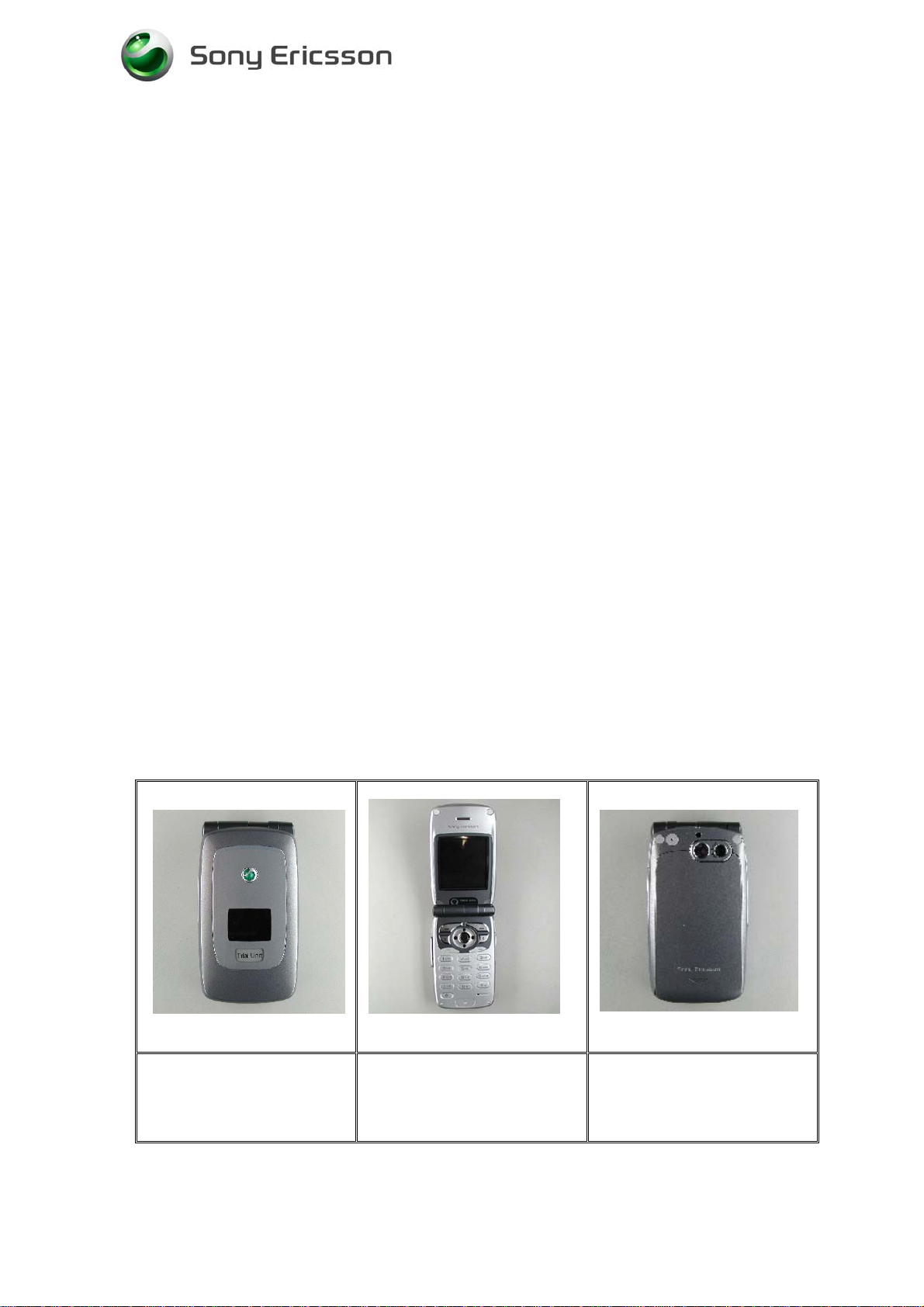
Front view
(Status Display)
3/000 21-1/FEA 209 544/77 A
Open view
(Main Display)
Sony Ericsson Mobile Communications AB
Back view
(Battery Cover)
2(60)
Page 3
Working Instructions,SP/ Mechanical
# Figure Instruction Note
1
2
Fig.1.1
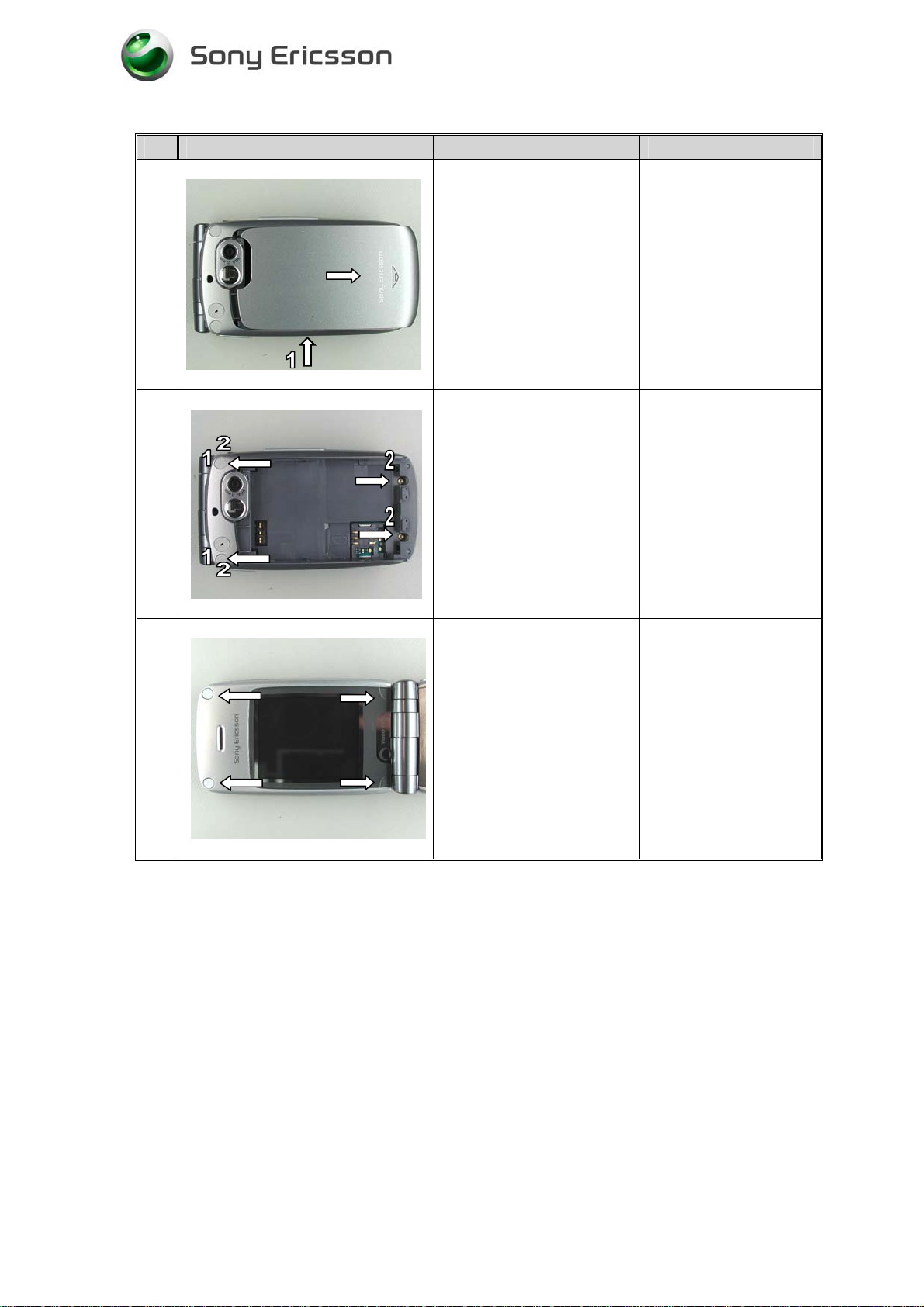
Remove the battery cover
with your fingers. Slide the
battery cover down. Take
out the battery.
(Fig.1.1)
Remove the two Lower
Rear Cabinet screw covers
with a dentist hook. (1)
Remove the four screws.
(2)
(Fig.1.2)
Check that the memory
stick is removed. (1).
Be careful not to
scratch the phone with
the dentist hook.
Do not reuse the screw
covers.
Fig.1.2
3
Fig.1.3
Remove the four Upper
Inside Cabinet screw
covers with a dentist hook.
Remove the four screws.
(Fig.1.3)
Do not reuse the
screws.
Do not reuse the screw
covers.
3/000 21-1/FEA 209 544/77 A
Sony Ericsson Mobile Communications AB
3(60)
Page 4
Working Instructions,SP/ Mechanical
# Figure Instruction Note
4
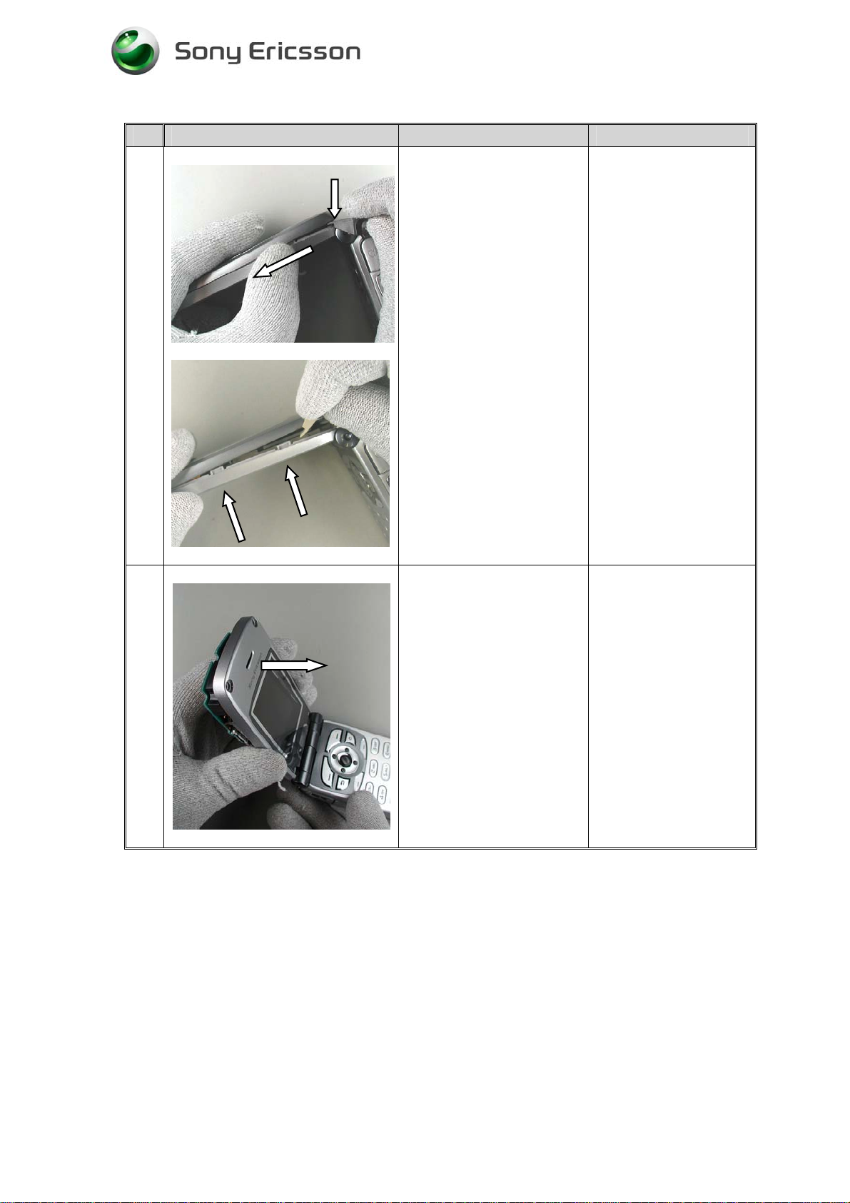
Remove the Upper Rear
Cabinet. Use opening tool
NTZ 112 302/2, if needed.
Start at hinge area and
twist the tool until the snap
fit latches opens. Continue
in the arrow direction.
(Fig.1.4)
Don’t touch the status
LCD.
Be careful not to
scratch the phone with
the opening tool.
LCD is only connected
to board with flex film
and falls easily out
from Frame.
Fig.1.4
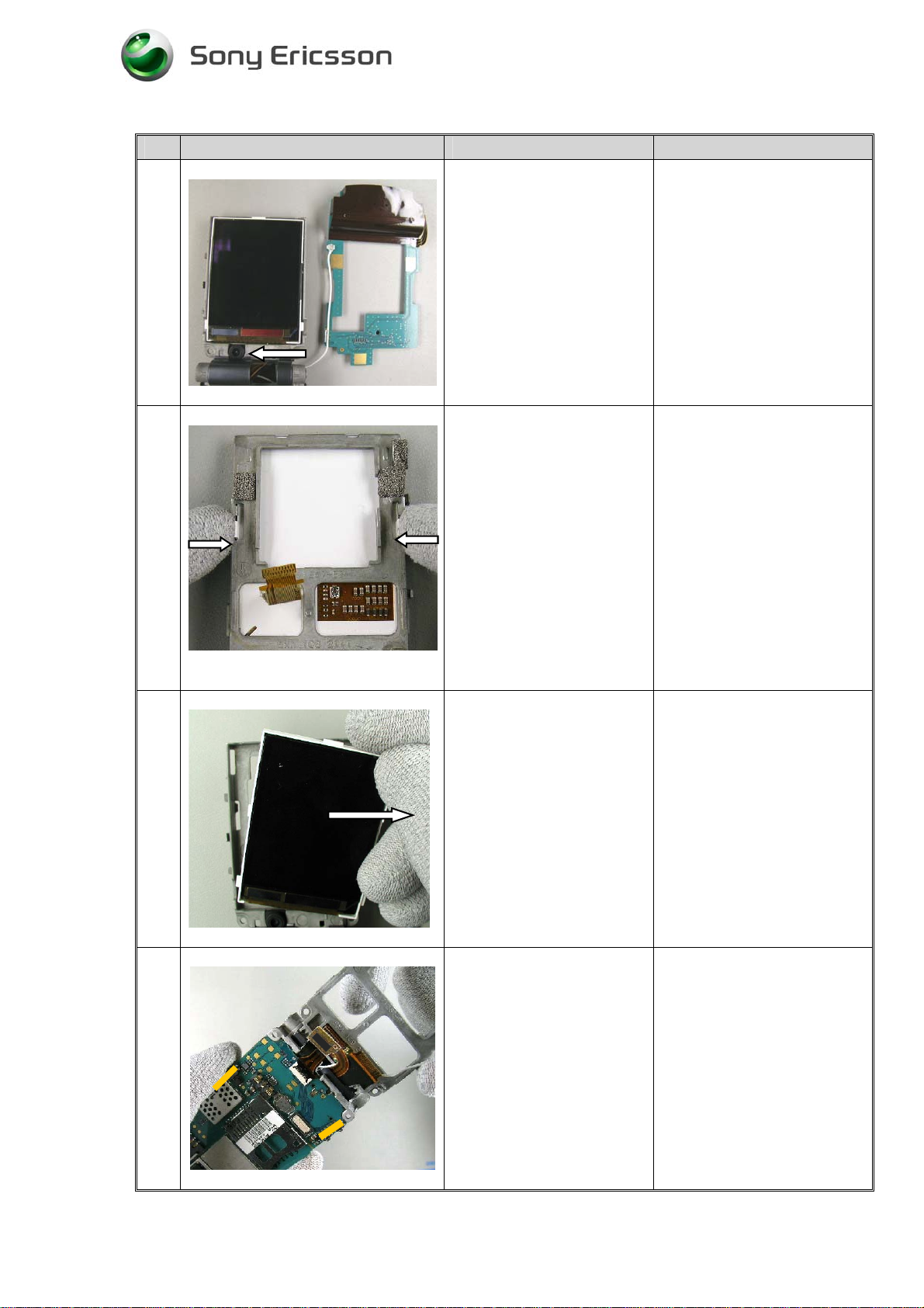
5
Remove the Upper Inside
Cabinet. Open the phone
between 90° and 180° like
the picture shows. Start at
the upper area and pull
forward in the arrow
direction.
(Fig.1.5)
Upper Rear Cabinet
assy separated
Don’t touch main LCD.
LCD is only connected
to board with flex film
and falls easily out of
Frame.
Fig.1.5
3/000 21-1/FEA 209 544/77 A
Sony Ericsson Mobile Communications AB
Upper Inside Cabinet
assy separated
4(60)
Page 5
Working Instructions,SP/ Mechanical
# Figure Instruction Note
6
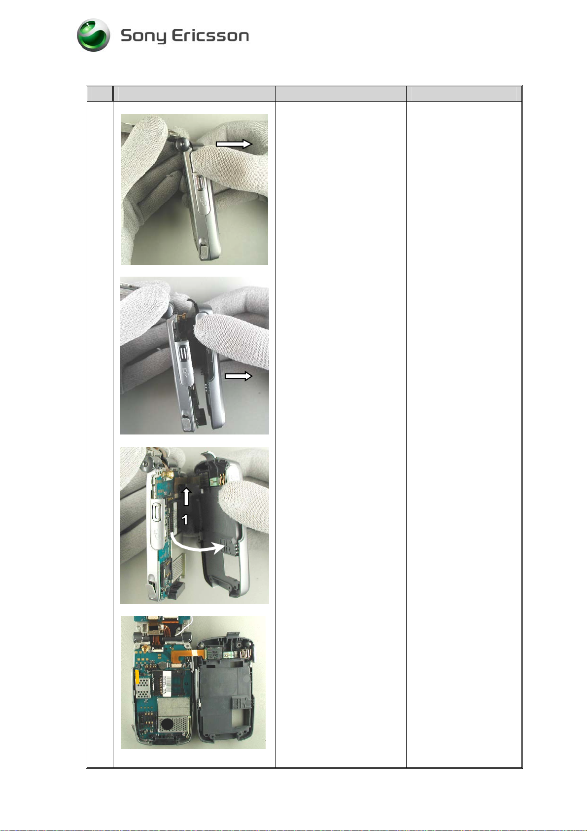
Remove the Lower Rear
Cabinet. Use your fingers
or opening tool NTZ 112
302/2, if needed.
Start at hinge area and pull
gently.
“Open” Lower Rear
Cabinet cautiously as VGA
camera flex still connects
to Lower Rear Cabinet
assembly (at volume key
side).
Fold the Lower Rear
Cabinet 180°. Be careful as
the VGA camera flex is
connected to the PCB.
VGA camera flex (1).
Be careful with the
camera flex film.
Fig.1.6
3/000 21-1/FEA 209 544/77 A
Sony Ericsson Mobile Communications AB
(Fig.1.6)
5(60)
Page 6
Working Instructions,SP/ Mechanical
# Figure Instruction Note
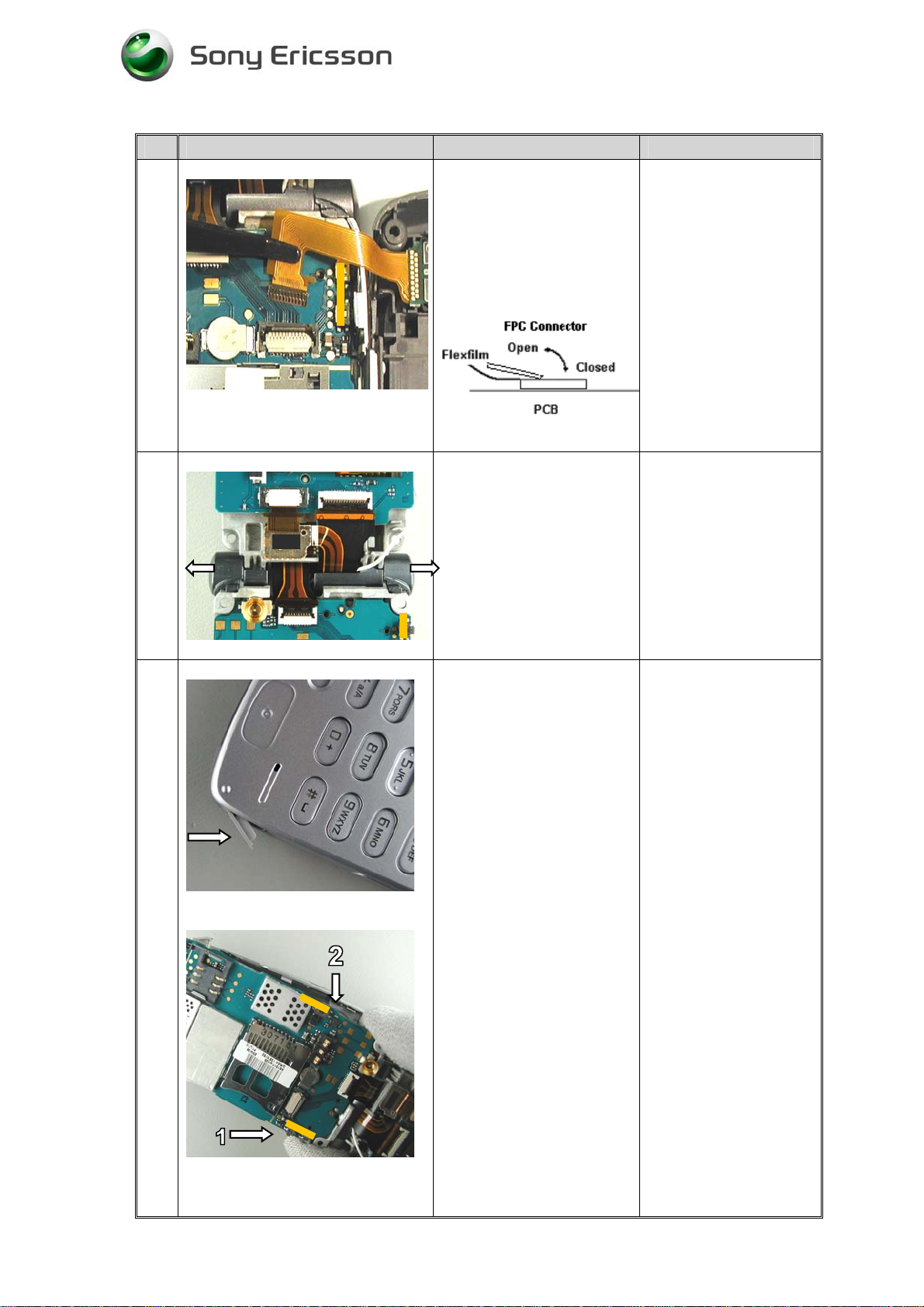
7
Fig.1.7
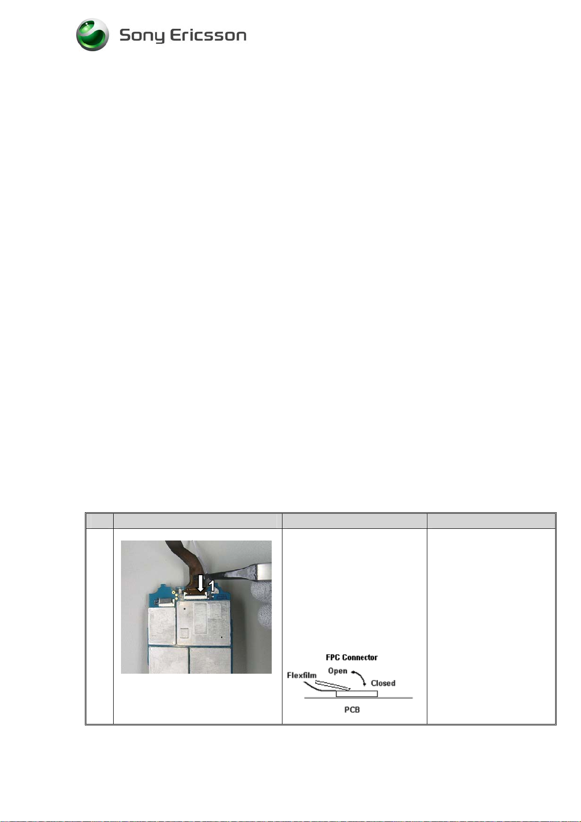
Open the FPC connector.
Remove VGA camera flex
film. Use Flex film
assembly Tool NTZ
112521.
(Fig.1.7)
Lower rear cabinet
assy separated
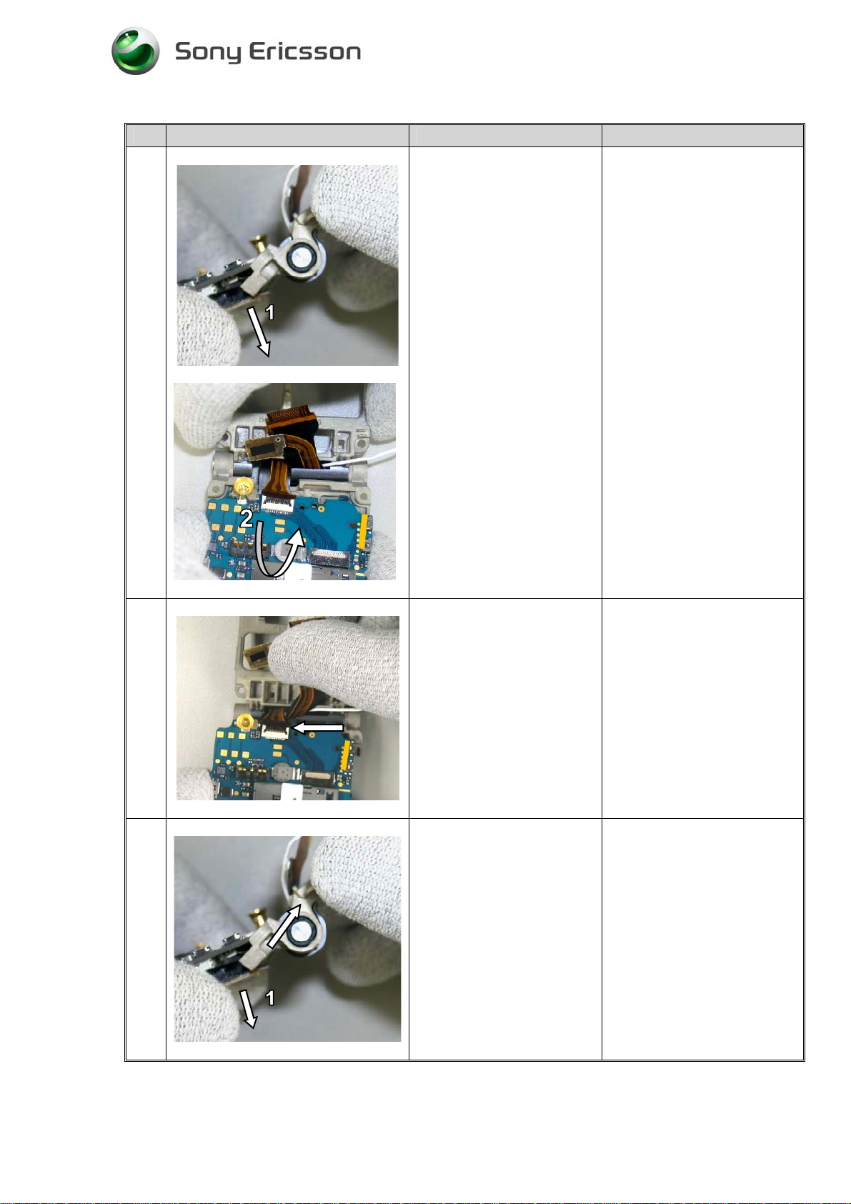
8
9
Fig.1.8
Fig.1.9
Remove the two hinge
covers with your fingers in
the arrows direction.
(Fig.1.8)
Open the USB cover
(located close to the
microphone), at the Lower
Inside Cabinet. To be able
to remove the PCB.
Turn the phone around so
that the PCB is visible
Open the phone 180° and
remove Lower Inside
Cabinet from main PCB
(incl. Frame and Sub PCB)
Start at hinge part and
continue to system
connector.
Make sure that the volume
switches (1) and the
camera switch (2) not are
damaged.
Hold the assy in the
Frame hinge.
Be careful so that the
volume switches (1)
and camera switch (2)
not are damaged.
Lower Inside Cabinet
assy separated.
3/000 21-1/FEA 209 544/77 A
Sony Ericsson Mobile Communications AB
(Fig.1.9)
6(60)
Page 7
Working Instructions,SP/ Mechanical
# Figure Instruction Note
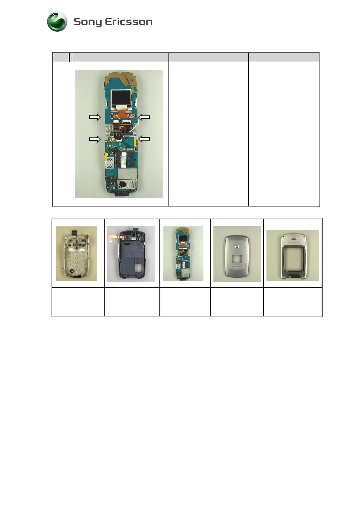
10
Fig.1.10
Hold the Main PCB and
Frame together when
handling the phone to
avoid main PCB to
separate from the
Frame. See arrows.
Main PCB and Sub
PCB assy separated
from cabinets.
Lower Inside Cabinet
Lower Rear Cabinet Main PCB SUB PCB Upper Rear Cabinet Upper Inside Cabinet
3/000 21-1/FEA 209 544/77 A
Sony Ericsson Mobile Communications AB
7(60)
Page 8
Working Instructions,SP/ Mechanical
# Figure Instruction Note
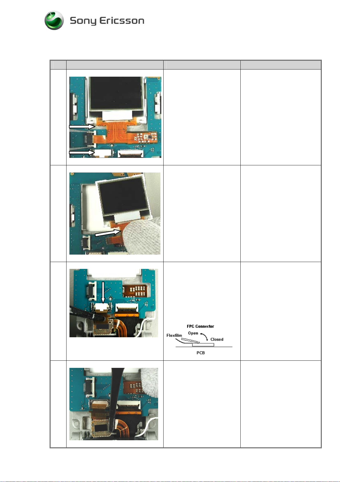
11
Fig. 1.11
12
Push the Status LCD
connector in the arrows
direction with a pair of
tweezers.
Disconnect the status LCD
flexfilm by using Flexfilm
assembly tool NTZ 112521.
(Fig.1.11)
Remove the Status LCD
from Sub PCB with your
fingers.
Fig.1.12
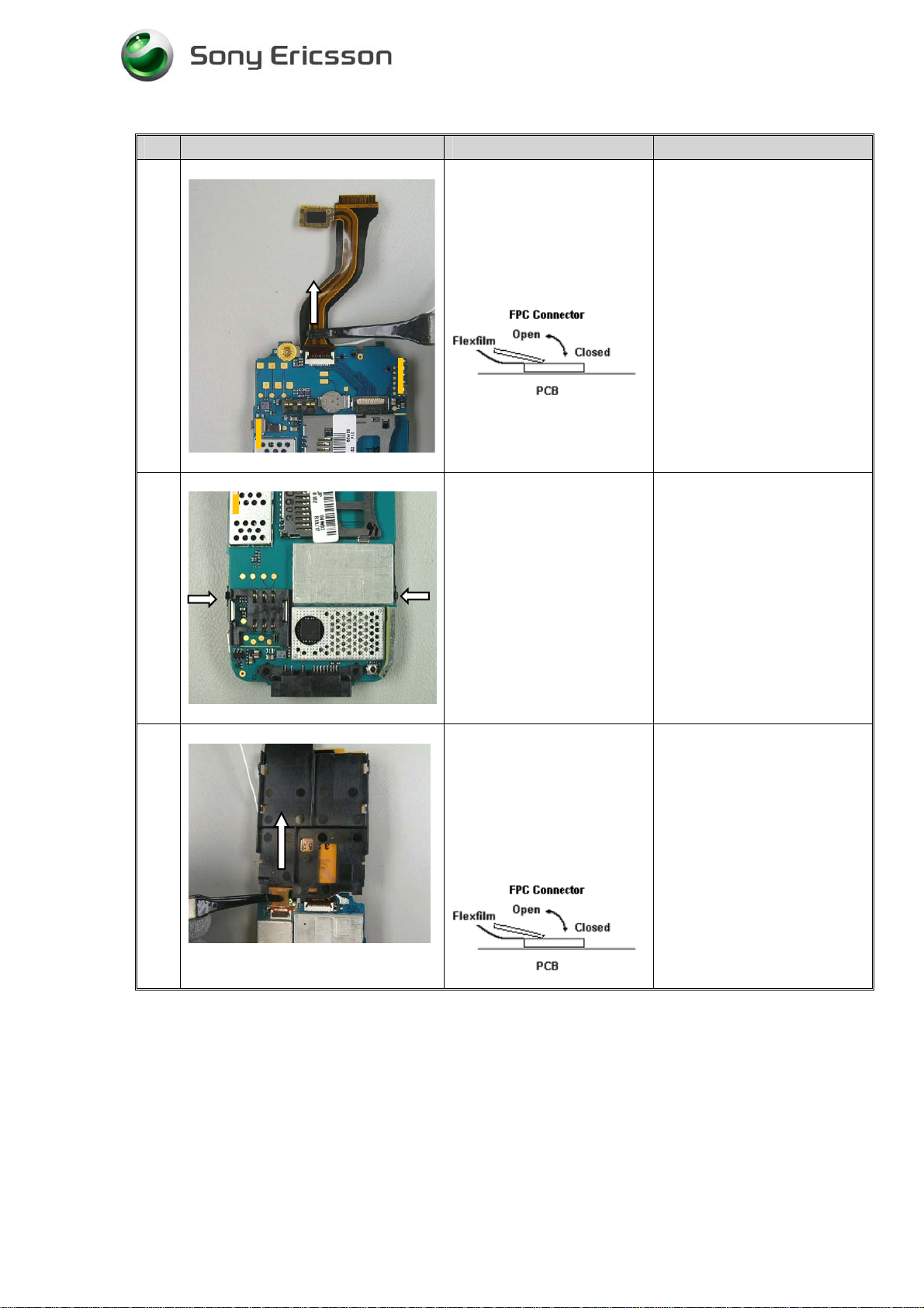
13
Fig. 1.13
14
(Fig.1.12)
Remove the tape (Tape
connector upper) and open
Main LCD FPC connector
and remove Main LCD flex
film with Flex film
assembly Tool NTZ
112521.
(Fig.1.13)
Disconnect CIF camera flex
with Flex film assembly
Tool NTZ 112521.
Be careful not to damage the
flex film.
Be careful handling the flex
film.
Fig.1.14
3/000 21-1/FEA 209 544/77 A
Sony Ericsson Mobile Communications AB
To avoid damage on the
camera connector, start
carefully at one side and
continue at the other side.
(Fig.1.14)
8(60)
Page 9
Working Instructions,SP/ Mechanical
# Figure Instruction Note
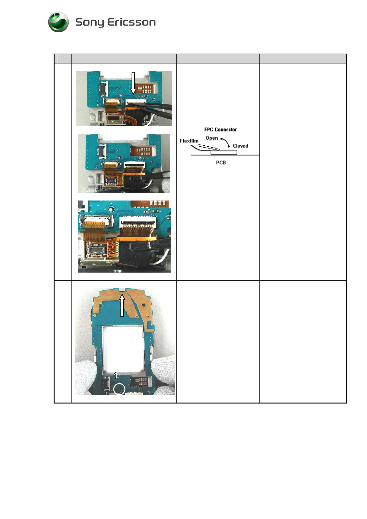
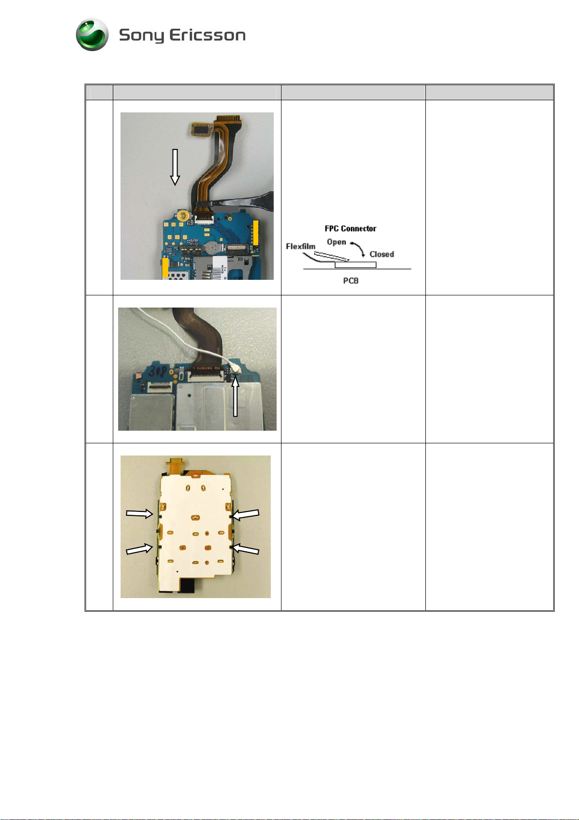
15
Open the FPC connector
with a pair of tweezers and
disconnect Main PCB flex.
Flex film assembly Tool
NTZ 112521.
(Fig.1.15)
Fig.1.15
17
Fig.1.17
Lift up the Sub PCB from
the guiding pin (1) and
slide the PCB in the arrow
direction. Fold the Sub
PCB beside and turn the
phone around.
(Fig.1.17)
3/000 21-1/FEA 209 544/77 A
Sony Ericsson Mobile Communications AB
9(60)
Page 10
Working Instructions,SP/ Mechanical
# Figure Instruction Note
18
Fig.1.18
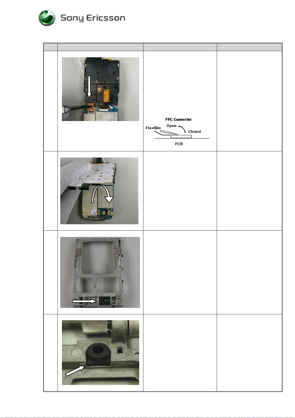
19
Press out the Cif camera
with your finger or a pair of
tweezers.
(Fig.1.18)
Turn the phone around.
Loosen the Main LCD by
pressing the snap fit hooks
in the arrows direction with
your fingers.
Be careful, not to scratch the
Camera lens.
Fig.1.19
20
Fig.1.20
21
(Fig.1.19)
Turn the phone around and
remove the Main LCD.
(Fig.1.20)
Turn the phone around.
Fig.1.21
3/000 21-1/FEA 209 544/77 A
Sony Ericsson Mobile Communications AB
(Fig.1.21)
10(60)
Page 11
Working Instructions,SP/ Mechanical
# Figure Instruction Note
22
To release the main board
from the hinge frame:
Hold the Main PCB and
Frame as the picture shows.
Bend the keyboard support
down in the arrow direction
(1).
23
24
Fig.1.22
Fig.1.23
Then bend Main PCB in the
arrow direction (upwards)
(2).
(Fig.1.22)
Hold the Camera flex and
Hinge flex in your right
hand.
Slide the Camera and
Hinge flex in the arrow
direction and lift them out
of the hinge.
(Fig.1.23)
To release the frame from
the Main PCB. Press down
the Keyboard support (1)
and remove the frame in the
arrow direction.
Fig.1.24
3/000 21-1/FEA 209 544/77 A
Sony Ericsson Mobile Communications AB
(Fig.1.24)
11(60)
Page 12
Working Instructions,SP/ Mechanical
# Figure Instruction Note
25
Fig.1.25
26
Open the Camera flex FPC
connector and remove the
Camera flex.
Use Flex film assembly
Tool NTZ 112521.
(Fig.1.25)
Turn the Main PCB around
and release the two
keyboard support snap fit
hooks with a pair of
tweezers.
Fig.1.26
27
Fig.1.27
(Fig.1.26)
Turn the phone around.
Fold the keyboard support
forward and open Keyboard
support connector.
Use Flex film assembly
Tool NTZ 112521.
(Fig.1.27)
3/000 21-1/FEA 209 544/77 A
Sony Ericsson Mobile Communications AB
12(60)
Page 13
Working Instructions,SP/ Mechanical
# Figure Instruction Note
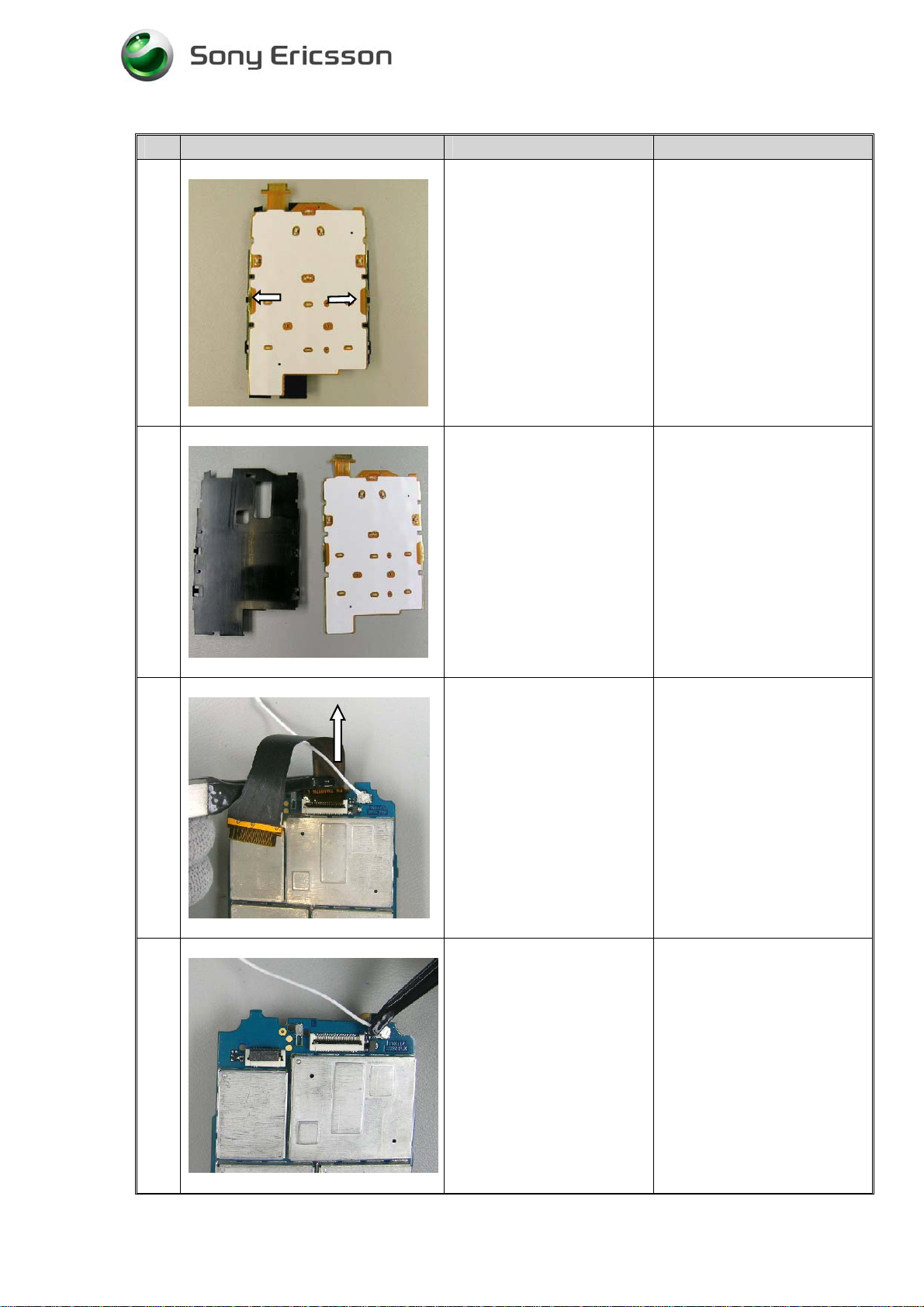
28
Fig.1.28
29
Turn the keyboard support
around.
Open carefully the two
snap fit hooks in the arrows
direction.
(Fig.1.28)
Lift up the keyboard PCB
from the keyboard support.
Fig.1.29
30
Fig.1.30
31
(Fig.1.29)
Open the Hinge flex FPC
connector and remove the
hinge flex.
Use Flex film assembly
Tool NTZ 112521.
(Fig.1.30)
Remove the Coax cable by
using a pair of tweezers.
Fig.1.31
3/000 21-1/FEA 209 544/77 A
Sony Ericsson Mobile Communications AB
(Fig.1.31)
13(60)
Page 14
Working Instructions,SP/ Mechanical
2 Reassembly Upper & Lower cabinets
Tools
• Pair of tweezers
• Screwdriver: Set to 15Ncm ± 6 %. Torx 6
• Flex film assembly Tool NTZ 112 521
• Dentist hook
2.1 Equipment
2.2 Instruction
# Figure Instruction Note
1
• ESD-gloves (cotton gloves).
• ESD-wristband
• Keep all contact surfaces clean of dirt and hand-grease
• Use gloves and an ESD wrist strap.
Open the FPC connector.
Connect hinge flex film. Use
Flex film assembly Tool NTZ
112521 (1).
Use your finger to close the
FPC-connector.
Fig.2.1
3/000 21-1/FEA 209 544/77 A
Sony Ericsson Mobile Communications AB
(Fig.2.1)
14(60)
Page 15
Working Instructions,SP/ Mechanical
# Figure Instruction Note
2
Turn Main the PCB around
and connect the Camera flex
film. Use Flex film assembly
Tool NTZ 112521.
Use your finger to close the
FPC-connector.
(Fig.2.2)
Fig.2.2
3
4
Fig.2.3
Connect the Coax cable. Use a
pair of tweezers.
(Fig.2.3)
Position the Keyboard PCB on
the keyboard support guiding
pins (arrows) and snap fit it on
the keyboard support.
(Fig.2.4)
Fig.2.4
3/000 21-1/FEA 209 544/77 A
Sony Ericsson Mobile Communications AB
15(60)
Page 16
Working Instructions,SP/ Mechanical
# Figure Instruction Note
5
6
Fig.2.5
Turn the phone around and
open the FPC connector.
Connect the Keyboard
assembly flex film. Use Flex
film assembly Tool NTZ
112521.
Use your finger to close the
FPC-connector.
(Fig.2.5)
Fold down the Keyboard
support in the arrow direction
and snap fit it on the Main
PCB.
Fig.2.6
7
8
Fig.2.7
(Fig.2.6)
Place the gasket in the frame.
(Fig.2.7)
Fig.2.8
3/000 21-1/FEA 209 544/77 A
Sony Ericsson Mobile Communications AB
Turn the frame around and
check that the gasket is in
correct position.
(Fig.2.8)
16(60)
Page 17
Working Instructions,SP/ Mechanical
# Figure Instruction Note
9
10
Fig.2.9
Place the Cif camera in the
frame.
(Fig.2.9)
Place the frame in front of
you.
Fig.2.10
(Fig.2.10)
3/000 21-1/FEA 209 544/77 A
Sony Ericsson Mobile Communications AB
17(60)
Page 18
Working Instructions,SP/ Mechanical
# Figure Instruction Note
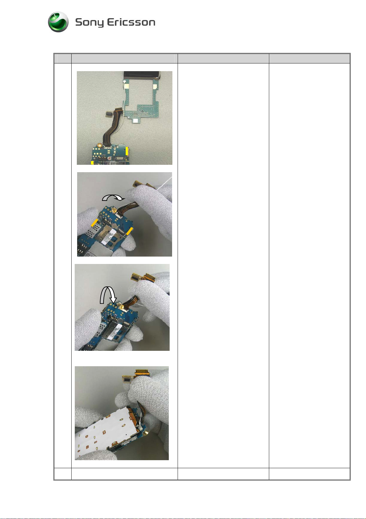
11
Place the Main PBA and Sub
PBA in front of you.
Hold Main PCB in your left
hand.
Hold camera flex film and
hinge flex film between your
right thumb and forefinger.
Rotate Main PCB 360 degrees
around antenna cable as in
following picture sequence.
(Fig.2.11)
3/000 21-1/FEA 209 544/77 A
Sony Ericsson Mobile Communications AB
18(60)
Page 19

Working Instructions,SP/ Mechanical
# Figure Instruction Note
11
Main PCB 360 degrees
rotated.
12
Fig.2.11
Fig.2.12
Place the Frame in front of
you.
(Fig.2.12)
3/000 21-1/FEA 209 544/77 A
Sony Ericsson Mobile Communications AB
19(60)
Page 20

Working Instructions,SP/ Mechanical
# Figure Instruction Note
13
Slide the flex films and
antenna cable into the hinge
cover gap in the arrows
direction (1).
14
Continue to the end of the
hinge cover gap (2).
(Fig.2.13)
Fig.2.13
To assemble the main PCB
and frame:
Hold the Main PCB and frame
as the picture shows.
Hold Keyboard support down
(1) and fit the guiding pins into
the frame (2).
Be careful, the keyboard
support will easily separate
from main PCB.
Fig.2.14
3/000 21-1/FEA 209 544/77 A
Sony Ericsson Mobile Communications AB
(Fig.2.14)
20(60)
Page 21

Working Instructions,SP/ Mechanical
# Figure Instruction Note
15
Turn the phone around and
place the Main LCD in the
Frame and snap fit it.
Be careful handling the
Main LCD to avoid dust
and contamination.
Fig.2.15
16
(Fig.2.15)
Do not press in the middle
of the LCD.
Place the Sub PCB on the
Frame and slide down Sub
PCB in the arrow direction
until the guiding pin is visible
(1).
(Fig.2.16)
Fig.2.16
17
Fig.2.17
Connect following flex films
on the PCB:
Main LCD flex (1).
Main PCB flex (2).
Camera flex (3).
Use Flexfilm assembly Tool
NTZ 112521.
Apply the new tape connector
upper, on the main LCD
connector.
Apply a new B2B Support pad
on the Cif camera connector, if
needed.
(Fig.2.17)
3/000 21-1/FEA 209 544/77 A
Sony Ericsson Mobile Communications AB
21(60)
Page 22

Working Instructions,SP/ Mechanical
# Figure Instruction Note
18
Fig.2.18
19
Reconnect the status LCD
flexfilm by using Flexfilm
assembly Tool NTZ 112521.
Push the Status LCD
connector in the arrows
direction with a pair of
tweezers.
(Fig.2.18)
Place the Coax cable on the
guiding hooks on Frame.
(Fig.2.19)
Fig.2.19
20
Fig.2.20
To insert the main PCB in
Lower Inside Cabinet:
Open the USB cover (located
close to the microphone), at
the Lower Inside Cabinet.
Put main PCB (incl Frame and
sub PCB) into the Lower
Inside Cabinet. Start by
placing volume switches ( 1 )
correctly, continue with
camera switch ( 2 ) and finally
fit lower part (system
connector) into Lower Inside
Cabinet.
(Fig.2.20)
Assure that the Keypad
and microphone is
correctly mounted in the
Lower Inside Cabinet.
Assure that volume
switches and camera
switch not are damaged
when the main PCB is
inserted into Lower Inside
Cabinet.
3/000 21-1/FEA 209 544/77 A
Sony Ericsson Mobile Communications AB
22(60)
Page 23

Working Instructions,SP/ Mechanical
# Figure Instruction Note
21
22
Fig.2.21
Hold the assembly in your
hand; keep main PCB and
Lower Inside Cabinet together.
Assemble left and right hinge
covers. (The tap shall be
placed up close to main PCB,
see picture).
(Fig.2.21)
Put Lower Inside Cabinet
assembly and Lower Rear
Cabinet next to each other.
Connect VGA camera flex
film in FPC-connector; use
Flexfilm assembly Tool NTZ
112521.
The tap on the Hinge
Covers should be placed
up according to the arrows
on the picture.
Two variants of hinge
covers.
Be careful handling the
flex film.
Fig.2.22
Use your finger to close the
FPC-connector.
(Fig.2.22)
3/000 21-1/FEA 209 544/77 A
Sony Ericsson Mobile Communications AB
23(60)
Page 24

Working Instructions,SP/ Mechanical
# Figure Instruction Note
23
Assemble the Lower Rear
Cabinet to the Lower Inside
Cabinet.
Fold the Lower Rear Cabinet
against the Lower Inside
Cabinet, assure that camera
flex not is pinched. (1).
Fit the Lower Rear Cabinet
into the Lower Inside Cabinet
gently.
Snap fit Lower Rear Cabinet
latches by pressing gently
around the Lower rear
Cabinet.
Fig.2.23
3/000 21-1/FEA 209 544/77 A
Sony Ericsson Mobile Communications AB
Close the “phone” 90° and
snap fit hinge part
(Fig.2.23)
24(60)
Page 25

Working Instructions,SP/ Mechanical
# Figure Instruction Note
24
Check that the two taps (for
the Main display) are in place
and not broken.
If the taps are broken remove
them from the cabinet.
Snap fit the Upper Inside
Cabinet, start at hinge area.
Make sure that speaker
flex film not is pinched.
25
26
(Fig.2.24)
Fig.2.24
Snap fit the Upper Rear
Cabinet, start at hinge area and
continue to press on all four
Make sure that the speaker
flex film and the coax
cable not are pinched.
sides.
(Fig.2.25)
Fig.2.25
Open the phone in 130 degrees
angle.
Tighten the four Upper Inside
Cabinet screws according to
screw sequence in Fig.2.26.
15 Ncm ± 6 %. Torx 6
Fig.2.26
3/000 21-1/FEA 209 544/77 A
Sony Ericsson Mobile Communications AB
Mount the four Upper Inside
Cabinet screw covers with
your fingers.
(Fig.2.26)
2 variants of screw covers.
25(60)
Page 26

Working Instructions,SP/ Mechanical
# Figure Instruction Note
27
Close the phone and tighten
the four Lower Rear Cabinet
screws according to screw
sequence in Fig 2.27.
15Ncm ± 6 %. Torx 6
28
Fig.2.27
Mount the two Lower Rear
Cabinet screw covers with
your fingers.
(Fig.2.27)
Assemble the battery.
Slide the battery cover on to
Lower Rear Cabinet, in the
direction of the arrow.
(Fig.2.28)
1 variant of screw covers.
Fig.2.28
3/000 21-1/FEA 209 544/77 A
Sony Ericsson Mobile Communications AB
26(60)
Page 27

Working Instructions,SP/ Mechanical
3 Replacement of Mechanical Parts
3.1 Equipment
• ESD-gloves (cotton gloves).
• ESD-wristband
3.2 Instruction
• Screwdriver: Set to 15Ncm ± 6 %. Torx 6
• Keep all contact surfaces clean of dirt and hand-grease!
3.3 Vibrator
Tools
• Pair of tweezers
Instruction
• Disassemble the phone as described in 1 Disassembly Upper & Lower cabinets, step 1, 2
and 6.
# Figure Instruction Note
1
1.Use a pair of tweezers to lift
up the vibrator.
2.Place the new vibrator in
Lower Rear Cabinet cavity by
using a pair of tweezers.
(Fig.3.1)
Be careful handling the
connecting pins.
Do not lift/press the
vibrator in the flywheel.
Fig.3.1
• Assemble the phone as described in 2 Reassembly Upper & Lower cabinets, step 23
and 26-28.
3/000 21-1/FEA 209 544/77 A
Sony Ericsson Mobile Communications AB
27(60)
Page 28

Working Instructions,SP/ Mechanical
3.4 Audio jack cover
Tools
• Pair of tweezers
Instruction
• Disassemble the phone as described in 1 Disassembly Upper & Lower cabinets, step
1,2 and 6.
# Figure Instruction Note
1
1.Remove the Audio jack
cover from Lower Rear
Cabinet by twisting the cover
tap out of the cavity with your
fingers.
2.Assemble a new Audio jack
cover in the Lower Rear
Cabinet. Use your fingers.
(Fig.3.2)
Fig.3.2
• Assemble the phone as described in 2 Reassembly Upper & Lower cabinets, step 23
and 26-28.
3/000 21-1/FEA 209 544/77 A
Sony Ericsson Mobile Communications AB
28(60)
Page 29

Working Instructions,SP/ Mechanical
3.5 Audio jack
Tools
• Opening tool NTZ112 302/2
Instruction
• Disassemble the phone as described in 1 Disassembly Upper & Lower cabinets, step 1,2
and 6.
•
Disassemble the Vibrator as described in 3.3 Vibrator, step1.
# Figure Instruction Note
1
Open Audio jack cover with
your fingers.
2
Fig.3.3
(Fig.3.3)
1.Remove the Audio jack by
lifting the rear side. Use tool
NTZ112 302/2.
2. Place the new Audio jack in
cavity in Lower Rear Cabinet.
Start with the front, and then
carefully press down the back
of the Audio jack.
(Fig.3.4)
Be careful handling the
connecting pins.
Fig.3.4
• Assemble the Vibrator as described in 3.3 Vibrator, step1.
• Assemble the phone as described in 2 Reassembly Upper & Lower cabinets, step 23
and 26-28.
3/000 21-1/FEA 209 544/77 A
Sony Ericsson Mobile Communications AB
29(60)
Page 30

Working Instructions,SP/ Mechanical
3.6 MS-Duo cover
Tools
• Pair of tweezers
Instruction
• Disassemble the phone as described in 1 Disassembly Upper & Lower cabinets, step
1, 2 and 6, 7.
# Figure Instruction Note
1
1.Remove the MS-DUO cover
from the Lower Rear Cabinet
by twisting the cover tap out of
the cavity
Fig.3.5
2
Fig.3.6
• Assemble the phone as described in 2 Reassembly Upper & Lower cabinets, step 22,
23 and 26-28.
(Fig.3.5)
Assemble a new MS-Duo
cover in the Lower Rear
Cabinet.
(Fig.3.6)
3/000 21-1/FEA 209 544/77 A
Sony Ericsson Mobile Communications AB
30(60)
Page 31

Working Instructions,SP/ Mechanical
3.7 VGA camera
Tools
• Pair of tweezers
Instruction
Disassemble the phone as described in 1 Disassembly Upper & Lower cabinets, step 1,2
•
and 6.
# Figure Instruction Note
1
Use a tweezers to open the
VGA camera FPC connector.
Fig.3.7
2
(Fig.3.7)
Use Flexfilm assembly Tool
NTZ 112521 to remove the
VGA camera flex film.
(Fig.3.8)
Be careful handling the
Camera flex film.
Fig.3.8
3/000 21-1/FEA 209 544/77 A
Sony Ericsson Mobile Communications AB
31(60)
Page 32

Working Instructions,SP/ Mechanical
# Figure Instruction Note
3
Fig.3.9
4
Use Flexfilm assembly Tool
NTZ 112521 to lift up the
VGA camera and gasket.
(Fig.3.9)
Assemble a new Camera
gasket lower VGA, on the
VGA camera.
Be careful handling the
Camera flex film.
Fig.3.10
5
Fig.3.11
• Assemble the phone as described in 2 Reassembly Upper & Lower cabinets, step
22,23 and 26-28.
(Fig.3.10)
Assemble the Camera and
Camera gasket lower VGA, in
the Lower Rear Cabinet.
(Fig.3.11)
3/000 21-1/FEA 209 544/77 A
Sony Ericsson Mobile Communications AB
32(60)
Page 33

Working Instructions,SP/ Mechanical
3.8 Microphone
Tools
• Pair of tweezers
Instruction
• Disassemble the phone as described in 1 Disassembly Upper & Lower cabinets, step 1,2
6,7,8 and 9.
# Figure Instruction Note
1
1.Lift up the old microphone
from Lower Inside Cabinet.
Use a dentist hook.
Do not bend the
connecting pins.
The connecting pins should
be facing upwards.
Fig.3.13
• Assemble the phone as described in 2 Reassembly Upper & Lower cabinets, step 20,
21,22 and 26-28.
2. Press down the new
microphone with your fingers
or a pair of tweezers and hold
down for a couple of seconds.
Check that the microphone
gasket is in level with the edge
of the Microphone cavity.
(Fig.3.13)
3/000 21-1/FEA 209 544/77 A
Sony Ericsson Mobile Communications AB
33(60)
Page 34

Working Instructions,SP/ Mechanical
3.9 USB cover
Tools
• Pair of tweezers
Instructions
• Disassemble the phone as described in 1 Disassembly Upper & Lower cabinets, step 1,2
6,7,8 and 9.
# Figure Instruction Note
1
Remove the USB cover; use a
pair of tweezers to lift up the
cover tap, then pull out the
cover in the arrow direction.
(Fig.3.14)
Fig.3.14
2
Fig.3.15
• Assemble the phone as described in 2 Reassembly Upper & Lower cabinets, step 20,
21, 22 and 26-28.
Assemble a new USB cover in
the cavity in Lower Inside
Cabinet. Use a pair of
tweezers to lift the tap in
place.
(Fig.3.15)
3/000 21-1/FEA 209 544/77 A
Sony Ericsson Mobile Communications AB
34(60)
Page 35

Working Instructions,SP/ Mechanical
3.10 Keypad
Tools
• Pair of tweezers
Instruction
• Disassemble the phone as described in 1 Disassembly Upper & Lower cabinets, step 1, 2
and 6,7,8 and 9.
# Figure Instruction Note
1
Remove the old Keypad from
the Lower Inside Cabinet with
your fingers or a pair of
tweezers.
(Fig.3.16)
Fig.3.16
2
Fig.3.17
• Assemble the phone as described in 2 Reassembly Upper & Lower cabinets, step 20,
21, 22 and 26-28.
Place the new Keypad in
Lower Inside Cabinet.
Make sure that the volume and
camera switches pads are
correct placed (arrows).
(Fig.3.17)
3/000 21-1/FEA 209 544/77 A
Sony Ericsson Mobile Communications AB
35(60)
Page 36

Working Instructions,SP/ Mechanical
3.11 Status LCD
Tools
• Pair of tweezers
Instruction
• Disassemble the phone as described in 1 Disassembly Upper & Lower cabinets, step 3-5.
# Figure Instruction Note
1
Push the Status LCD
connector in the arrows
direction with a pair of
tweezers.
Disconnect the status LCD
flexfilm by using Flexfilm
assembly Tool NTZ 112521.
Fig.3.18
2
Fig.3.19
3
(Fig.3.18)
Remove the Status LCD from
the Sub PCB with your
fingers.
(Fig.3.19)
Connect the new status LCD
flexfilm by using Flexfilm
assembly Tool NTZ 112521.
Push the Status LCD
connector in the arrows
direction with a pair of
tweezers.
Fig.3.20
• Assemble the phone as described in 2 Reassembly Upper & Lower cabinets, step 24-
26.
3/000 21-1/FEA 209 544/77 A
Sony Ericsson Mobile Communications AB
(Fig.3.20)
36(60)
Page 37

Working Instructions,SP/ Mechanical
3.12 CIF camera
Tools
• Pair of tweezers
Instruction
• Disassemble the phone as described in 1 Disassembly Upper & Lower cabinets, step 3-5.
• Disassemble the Status LCD as described in 3.11 Status LCD, step1and 2.
# Figure Instruction Note
1
Remove the connector tape
upper on the Main LCD
connector (arrow). Open the
Main LCD FPC connector and
remove the Main LCD flex
film with Flexfilm assembly
Tool NTZ 112521.
Be careful not to damage
the flex film.
Fig.3.21
2
Fig.3.22
(Fig.3.21)
Disconnect the CIF camera
flex using Flexfilm assembly
Tool NTZ 112521.
To avoid damage on the
camera connector, start
carefully at one side and
continue at the other side.
(Fig.3.22)
Be careful handling the
flex film.
3/000 21-1/FEA 209 544/77 A
Sony Ericsson Mobile Communications AB
37(60)
Page 38

Working Instructions,SP/ Mechanical
# Figure Instruction Note
3
Open the FPC connector with
a pair of tweezers and
disconnect Main PCB flex by
using Flexfilm assembly Tool
NTZ 112521.
(Fig.3.23)
Fig.3.23
5
Fig.3.25
6
Lift up the Sub PCB from the
guiding pin (1) and slide the
PCB in the arrow direction.
Fold the Sub PCB beside and
turn the phone around.
(Fig.3.25)
Press out the Cif camera with
your finger or a pair of
tweezers.
(Fig.3.26)
Use gloves to avoid dust
and grease. Be careful
handling the camera lens.
Fig.3.26
3/000 21-1/FEA 209 544/77 A
Sony Ericsson Mobile Communications AB
38(60)
Page 39

Working Instructions,SP/ Mechanical
# Figure Instruction Note
7
Turn the phone around and
place a new camera gasket in
the Frame cavity.
(Fig.3.27)
Fig.3.27
8
Place the new Cif camera in
the gasket.
Apply the ground pad on the
camera
(Fig.3.28)
Check that the gasket is in
the right position.
Press down the camera in
the cavity.
Fig.3.28
9
Fig.3.29
3/000 21-1/FEA 209 544/77 A
Sony Ericsson Mobile Communications AB
Place the Sub PCB on the
Frame. Slide down Sub PCB
in the arrow direction until the
guiding pin is visible (1).
(Fig.3.29)
39(60)
Page 40

Working Instructions,SP/ Mechanical
# Figure Instruction Note
10
Connect following flex films
on the PCB:
Be careful handling the
flex films.
Fig.3.30
11
Main LCD flex (1).
Main PCB flex (2).
Camera flex (3).
Use Flexfilm assembly Tool
NTZ 112521.
Apply the new connector tape
upper, on the main LCD
connector.
Apply a new B2B Support pad
on the Cif camera connector, if
needed.
(Fig.3.30)
Place Status LCD in Frame
and connect flex film, use
Flexfilm assembly Tool NTZ
112521.
Close the connector; use
a pair of tweezers and push, in
the arrows direction.
(Fig.3.31)
Fig.3.31
• Assemble the phone as described in 2 Reassembly Upper & Lower cabinets, step 24-26.
3/000 21-1/FEA 209 544/77 A
Sony Ericsson Mobile Communications AB
40(60)
Page 41

Working Instructions,SP/ Mechanical
3.13 Main LCD
Tools
• Pair of tweezers
Instructions
• Disassemble the phone as described in 1 Disassembly Upper & Lower cabinets, step 3,4
and 5.
• Disassemble the phone as described in 1 Disassembly Upper & Lower cabinets, step 11-
18.
# Figure Instruction Note
1
Release the Main LCD by
pressing the snap fit hooks in
the arrows direction with your
fingers.
Fig.3.32
2
Fig.3.33
(Fig.3.32)
Turn the phone around and
remove the Main LCD.
Fig.3.33
3/000 21-1/FEA 209 544/77 A
Sony Ericsson Mobile Communications AB
41(60)
Page 42

Working Instructions,SP/ Mechanical
# Figure Instruction Note
3
Fig.3.34
4
Place the new Main LCD in
the in Frame and press gently
on the sides of the LCD until it
snap fit in frame.
(Fig.3.34)
Place the Sub PCB on the
Frame and slide down Sub
PCB in the arrow direction
until the guiding pin is visible
(1).
Be careful handling the
Main LCD to avoid dust
and contamination.
Do not press in the middle
of the LCD.
Fig.3.35
5
(Fig.3.35)
Connect following flex films
on the PCB:
Main LCD flex (1).
Main PCB flex (2).
Camera flex (3).
Use Flexfilm assembly Tool
NTZ 112521.
Fig.3.36
3/000 21-1/FEA 209 544/77 A
Sony Ericsson Mobile Communications AB
Apply the new connector tape
upper, on the main LCD
connector.
Apply B2B Support pad on the
Cif camera connector, if
needed.
(Fig.3.36)
42(60)
Page 43

Working Instructions,SP/ Mechanical
# Figure Instruction Note
6
(Fig.3.37)
• Assemble the phone as described in 2 Reassembly Upper & Lower cabinets, step 24-
26.
Turn the phone around and
place Status LCD in Frame.
Connect the flex film, use
Flexfilm assembly Tool NTZ
112521.
Close the connector, use
a pair of tweezers and push in
the arrows direction.
(Fig.3.37)
3.14 Icon
Tools
• Dentist hook
Instructions
•
# Figure Instruction Note
1
Fig.3.38
Remove the icon with a dentist
hook.
(Fig.3.38)
Handle careful to avoid
scratches.
3/000 21-1/FEA 209 544/77 A
Sony Ericsson Mobile Communications AB
43(60)
Page 44

Working Instructions,SP/ Mechanical
# Figure Instruction Note
2
Fig.3.39
3
Place the icons guiding pin
into the guiding hole in Upper
Rear Cabinet. Use a pair of
tweezers.
(Fig.3.39)
Press down the icon with your
finger for a couple of seconds.
(Fig.3.40)
Use a pair of tweezers.
Fig.3.40
3/000 21-1/FEA 209 544/77 A
Sony Ericsson Mobile Communications AB
44(60)
Page 45

Working Instructions,SP/ Mechanical
3.15 Camera mirror
Tools
• Soldering Iron
Instruction
• Disassemble the phone as described in 1 Disassembly Upper & Lower cabinets, step
1,2 and 6,7.
• Disassemble the VGA camera as described in 3.5 VGA camera, step1-3.
• Disassemble the Vibrator as described in 3.3 Vibrator, step1.
# Figure Instruction Note
1
Place a soldering iron tip at the
pin until it melts.
Do not touch the vibrator
cavity with the soldering iron.
Then rapidly lift up Lower
Rear Cabinet and press out
camera mirror with the
backside of a pair of tweezers
in the arrows direction.
(Fig.3.41)
Do not use this soldering
iron for soldering any
electrical component.
Soldering temp 155
degrees Celsius.
+/- 5 degrees.
Tip width 2 mm.
Clean the cavity from all
plastic residues.
Fig.3.41
3/000 21-1/FEA 209 544/77 A
Sony Ericsson Mobile Communications AB
45(60)
Page 46

Working Instructions,SP/ Mechanical
2
Snap fit the Camera mirror
guiding pin into Lower Rear
Cabinet (1) and press down
Camera mirror (2).
Use a pair of tweezers or
your fingers.
3
Fig.3.42
Then turn the Lower Rear
Cabinet around with the
Camera mirror down.
(Fig.3.42)
Press down the Lower Rear
Cabinet and place the
soldering iron tip at the pin
until it melts. Remove the
soldering iron and continue to
hold down the Lower Rear
Cabinet for a couple of
seconds.
Be careful; do not touch the
vibrator cavity with the
soldering iron.
Do not use this soldering
iron tip for soldering any
electrical component.
Fig.3.43
• Assemble the vibrator as described in 3.3 Vibrator, step 2.
• Assemble the VGA Camera as described in 3.5 VGA Camera, step 2.
• Assemble the phone as described in 2 Reassembly Upper & Lower cabinets, step 22,
23 and 26-28.
3/000 21-1/FEA 209 544/77 A
Sony Ericsson Mobile Communications AB
(Fig.3.43)
46(60)
Page 47

Working Instructions,SP/ Mechanical
3.16 Frame Assembly
Tools
• Pair of tweezers
• Flex film assembly Tool NTZ 112 521
• Dentist hook
Instruction
• Disassemble the phone as described in 1 Disassembly Upper & Lower cabinets, step
1-24.
# Figure Instruction Note
1
Frame separated
(Fig.3.44)
Fig.3.44
• Assemble the phone as described in 2 Reassembly Upper & Lower cabinets, 7 – 28.
3/000 21-1/FEA 209 544/77 A
Sony Ericsson Mobile Communications AB
47(60)
Page 48

Working Instructions,SP/ Mechanical
3.17 Hinge Covers - Right and Left
Tools
Instruction
• Disassemble the phone as described in 1 Disassembly Upper & Lower cabinets, step
1-2.
# Figure Instruction Note
1
Remove hinge covers with
your fingers in the arrows
direction.
(Fig.3.45)
Fig.3.45
2
Fig.3.46
• Assemble the phone as described in 2 Reassembly Upper & Lower cabinets, step,23-
28.
Assemble hinge covers with
your fingers in the arrows
direction.
(Fig.3.46)
3/000 21-1/FEA 209 544/77 A
Sony Ericsson Mobile Communications AB
48(60)
Page 49

Working Instructions,SP/ Mechanical
3.18 Hinge Covers-Inner
Tools
Instruction
• Disassemble the phone as described in 1 Disassembly Upper & Lower cabinets, step
1-9, 11-18 and 21-24.
# Figure Instruction Note
1
Disassemble the hinge covers
with your fingers in the arrows
directions.
Reassemble the new ones in
the opposite direction.
(Fig.3.47)
Be careful handling the
LCD to avoid
contamination.
Fig.3.47
2
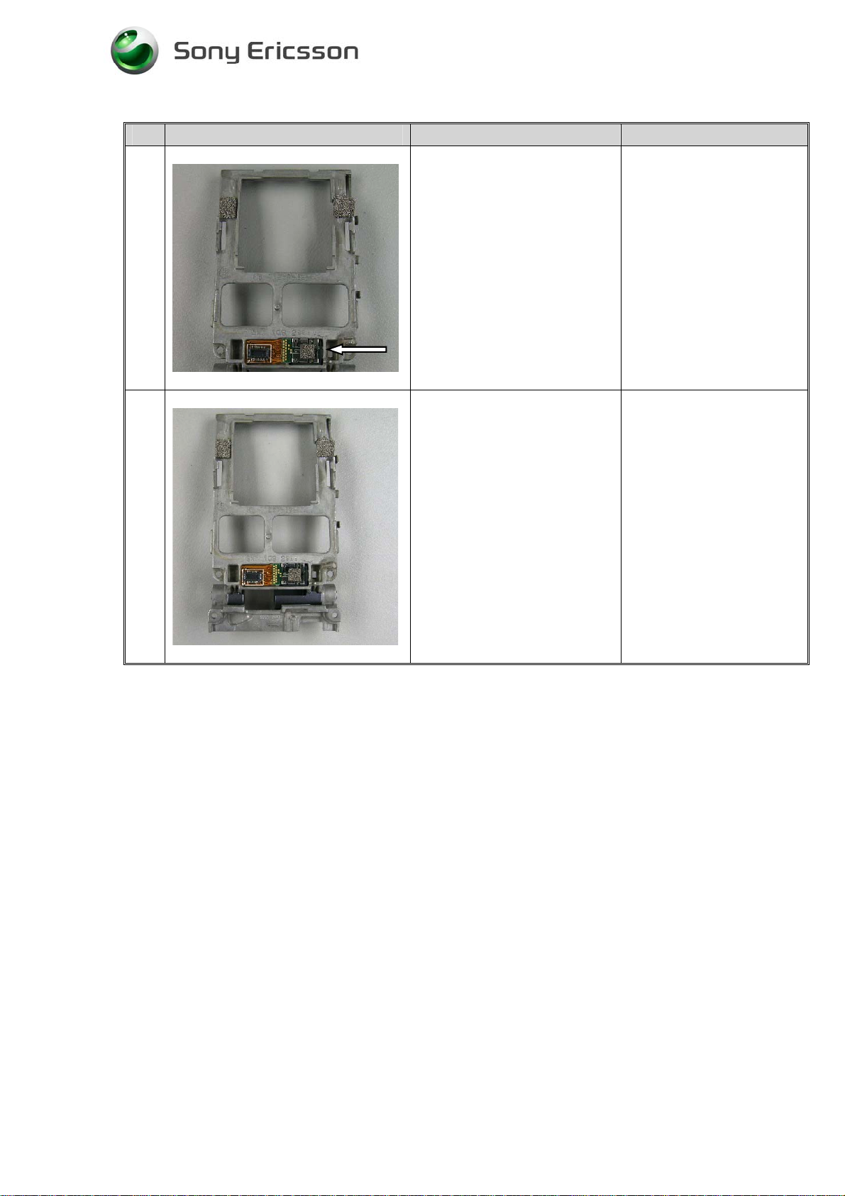
Control that the gap in the
large hinge cover, is parallel to
the hole in the frame (1).
Check that the hooks in the
hinge covers fit into the frame
(2).
(Fig.3.48)
Be careful handling the
LCD to avoid
contamination.
Fig.3.48
• Assemble the phone as described in 2 Reassembly Upper & Lower cabinets, 7-11 and
14-28.
3/000 21-1/FEA 209 544/77 A
Sony Ericsson Mobile Communications AB
49(60)
Page 50

Working Instructions,SP/ Mechanical
3.19 IMD Plate (upper rear cabinet)
Tools
Instruction
• Disassemble the phone as described in 1 Disassembly Upper & Lower cabinets, step
3-5
# Figure Instruction Note
1
Place the Upper Rear IMD
tape in the fixture.
Remove the protection foil.
(Fig.3.49)
Fig.3.49
2
Fig.3.50
3
Place Upper Rear IMD plate in
the fixture and press down
with your fingers.
(Fig.3.50)
Lift up the IMD plate from the
fixture and remove the
protection foil.
(Fig.3.51)
.
Fig.3.51
3/000 21-1/FEA 209 544/77 A
Sony Ericsson Mobile Communications AB
50(60)
Page 51

Working Instructions,SP/ Mechanical
# Figure Instruction Note
4
5
Fig.3.52
Place the IMD plate on the
Upper Rear Cabinet. Start at
the icon side (1).
(Fig.3.52)
Turn the Upper Rear Cabinet
around and press gently down
the Upper Inside Cabinet with
your fingers.
Remember to assemble the
icon.
• Assemble the icon as described in 3.14 Icon steps 2-3.
• Reassemble the phone as described in 1 Reassembly Upper & Lower cabinets, step
24-26.
(Fig.3.53)
Fig.3.53
3/000 21-1/FEA 209 544/77 A
Sony Ericsson Mobile Communications AB
51(60)
Page 52

Working Instructions,SP/ Mechanical
3.20 Upper inside cabinet assembly
Tools
Instruction
• Disassemble the phone as described in 1 Disassembly Upper & Lower cabinets, step
3-5.
# Figure Instruction Note
1
Remove the Upper Inside
Cabinet. Open the phone
between 90° and 180° like the
picture show. Start at the upper
area and pull forward in the
arrow direction.
(Fig.3.54)
Don’t touch main LCD.
Status LCD is only
connected to board with
flex film and falls easily
out of Frame.
2
(Fig.3.54)
Reassembly the new Upper
Inside Cabinet assembly. Start
at hinge area.
(Fig.3.55)
(Fig.3.55)
• Reassemble the phone as described in 1 Reassembly Upper & Lower cabinets, step
24-26.
3/000 21-1/FEA 209 544/77 A
Sony Ericsson Mobile Communications AB
52(60)
Page 53

Working Instructions,SP/ Mechanical
3.21 Magnet
Tools
• Pair of tweezers
• Flex film assembly Tool NTZ 112 521
• Dentist hook
Instruction
• Disassemble the phone as described in 1 Disassembly Upper & Lower cabinets, step
3-5.
# Figure Instruction Note
1
Assemble the magnet in Upper
Inside Cabinet cavity by using
a pair of tweezers (1).
Fig.3.56
• Assemble the phone as described in 2 Reassembly Upper & Lower cabinets, 24-26.
Then press down the magnet
with your finger (2).
(Fig.3.56)
3/000 21-1/FEA 209 544/77 A
Sony Ericsson Mobile Communications AB
53(60)
Page 54

Working Instructions,SP/ Mechanical
3.22 Keyboard support Complete and Keyboard PCB
Tools
• Flexfilm assembly Tool NTZ 112521
Instruction
• Disassemble the phone as described in 1Disassembly Upper & Lower cabinets,step1-
2 ,6,7 and 9.
# Figure Instruction Note
1
Hold the Main PCB and
Frame, bend the keyboard
support down (1)
Then bend Main PCB in the
arrow direction (upwards) (2).
Fig.3.57
2
Fig.3.58
3
(Fig.3.57)
Turn the Main PCB around and
open the two keyboard support
snap fit hooks with a pair of
tweezers.
(Fig.3.58)
Turn the phone around. Fold
the keyboard support forward
and open Keyboard support
connector. Remove Keyboard
support and Keyboard PCB.
Use Flexfilm assembly Tool
NTZ 112521.
Fig.3.59
3/000 21-1/FEA 209 544/77 A
Sony Ericsson Mobile Communications AB
(Fig.3.59)
54(60)
Page 55

Working Instructions,SP/ Mechanical
# Figure Instruction Note
4
Open the hooks on the
Keyboard support in arrows
direction and remove
Keyboard PCB.
Fig.3.60
5
Fig.3.61
Assemble a new Keyboard
Support or a new Keyboard
complete PCB.
(Fig.3.60)
Open the FPC connector.
Assemble Keyboard support
Complete flex film. Use Flex
film assembly Tool NTZ
112521. Use your finger to
close the FPC-connector. Fold
down Keyboard support in the
arrow direction and snap fit it
on main PCB
(Fig.3.61)
3/000 21-1/FEA 209 544/77 A
Sony Ericsson Mobile Communications AB
55(60)
Page 56

Working Instructions,SP/ Mechanical
# Figure Instruction Note
6
Hold the Main PCB and
Frame, bend the keyboard
support down (1)
Then fit in the guiding pins on
Main PCB in the frame. (2).
Turn the phone around and
check that the keyboard PCB
flex film not have been
pinched.
(Fig.3.62)
Fig.3.62
• Assemble the phone as described in 2 Reassembly Upper & Lower cabinets, step 19-
22 and 26-28.
3/000 21-1/FEA 209 544/77 A
Sony Ericsson Mobile Communications AB
56(60)
Page 57

Working Instructions,SP/ Mechanical
3.23 Hinge flex PCB Assembly (Cif camera)
Tools
• Pair of tweezers
• Flex film assembly tool NTZ 112 521
• Dentist hook
Instruction
• Disassemble the phone as described in 1 Disassembly Upper & Lower cabinets, step
1-9,11-17 and 21-24.
# Figure Instruction Note
1
Open Camera flex FPC
connector and remove Camera
flex. Assemble a new Camera
flex and close the connector.
Fig.3.63
• Assemble the phone as described in 2 Reassembly Upper & Lower cabinets, 5-6,10-
14,16 -28.
Use Flex film assembly Tool
NTZ 112 521
(Fig.3.63)
3/000 21-1/FEA 209 544/77 A
Sony Ericsson Mobile Communications AB
57(60)
Page 58

Working Instructions,SP/ Mechanical
3.24 Flex film Hinge flex
Tools
• Flex film assembly tool NTZ 112 521
• Dentist hook
Instruction
• Disassemble the phone as described in 1 Disassembly Upper & Lower cabinets, step
1-9, 11-17 and 21-24.
# Figure Instruction Note
1
Open Hinge flex FPC
connector and remove Camera
flex. Assemble a new Hinge
flex and close the connector.
Fig.3.64
• Assemble the phone as described in 2 Reassembly Upper & Lower cabinets, 5-6,10-
14,16 -28.
Use Flexfilm assembly Tool
NTZ 112521.
(Fig.3.64)
3/000 21-1/FEA 209 544/77 A
Sony Ericsson Mobile Communications AB
58(60)
Page 59

Working Instructions,SP/ Mechanical
4 Label
Tools
• Hot air flow solder station
• Tweezers
• Zebra printer and computer
Instruction
This instruction should be used when you are intending to exchange an old label or assemble
a new one.
1. Read the old label and/or write the information into the Labelmake program.
2. Heat up the label with a hot air flow solder station.
3. Carefully remove the label, make sure that all residues are gone. Do not scratch the
cabinet. NOTE! Only one label is allowed on the cabinet.
4. Check that the right label format is loaded in the Zebra printer.
5. Write a new label by using the program Labelmake. Replace the CDA-number with the
KRH-number and R-state. Check that the printing is ok.
6. Take the new label and place it onto the cabinet according to Fig.4.1 Assure that label is
placed in the right position.
Fig.4.1
3/000 21-1/FEA 209 544/77 A
Sony Ericsson Mobile Communications AB
59(60)
Page 60

Working Instructions,SP/ Mechanical
5 Revision History
Rev. Date Changes / Comments
A 2004-04-19 First release
3/000 21-1/FEA 209 544/77 A
Sony Ericsson Mobile Communications AB
60(60)
 Loading...