

Page 1

Trouble Shooting Guide, Electrical
Trouble Shooting Guide, Electrical
Applicable for W600i, W600c
Contents
General.............................................................................................................................2
1
2
Repair Actions for Manual Test Failures.....................................................................3
2.1
Power On / Off ..................................................................................................3
2.2
Software Flash...................................................................................................3
2.3
Charging............................................................................................................3
2.4
Hands-Free connection (PHF)...........................................................................3
2.5
SIM....................................................................................................................3
2.6
Charging indicator (RED LED).........................................................................3
2.7
Display...............................................................................................................3
2.8
Illumination (Backlight or LEDs) .....................................................................4
2.9
Upper (rocker) Keypad Keys.............................................................................4
2.10
Lower (main) Keypad Keys ..............................................................................4
2.11
Volume Up Key.................................................................................................4
2.12
Volume Down Key............................................................................................4
2.13
Camera Key.......................................................................................................4
2.14
Lock key............................................................................................................4
2.15
On/Off key.........................................................................................................4
2.16
Gaming (A and B) Keys....................................................................................4
2.17
Media Player Key..............................................................................................4
2.18
Vibrator .............................................................................................................4
2.19
Earphone (Speaker)...........................................................................................4
2.20
Polyphonic RIGHT (speaker A) (speaker phone) .............................................4
2.21
Polyphonic LEFT (speaker B) ...........................................................................5
2.22
Polyphonic BOTH.............................................................................................5
2.23
Microphone .......................................................................................................5
2.24
Real Time Clock................................................................................................5
2.25
Camera...............................................................................................................5
2.26
Camera Flash.....................................................................................................5
2.27
Flip Sensor.........................................................................................................5
2.28
IR.......................................................................................................................5
2.29
Bluetooth...........................................................................................................5
2.30
FM Radio...........................................................................................................5
3
Repair Actions for Go/No Go Test Failures .................................................................5
4
Repair Actions for Calibration Routine Failures.........................................................6
4.1
GSM 850, 900, 1800, or 1900...........................................................................6
4.2
EDGE 850, 900, 1800, or 1900.........................................................................6
5
Revision History..............................................................................................................7
4/000 21-2/FEA 209 544/594 D
©
Sony Ericsson Mobile Communications AB
Page 2

Trouble Shooting Guide, Electrical
1 General
The purpose of this document is to indicate the electrical level repair actions associated with the different
failure symptoms.
For symptoms that have multiple repair actions, the repair actions are listed in order of their probability of
creating a successful repair. The first action has the highest probability, and subsequent actions have lower
probabilities. The intention is for the repair technician to implement the first repair action and then retest the
phone. If the phone continues to fail the same test, then the technician should continue to the second repair
action. If the phone continues to fail the same test after all of the repair actions are exhausted, then the
phone will be considered not reparable at this level.
This document should be used only after the actions from the Mechanical Trouble Shooting Guide have
been exhausted for the specific symptom.
Voltage, current, and resistance information is provided for some symptoms to enable faster repairs.
Perform current measurements using a dummy battery and power supply with digital current display. The
phone should be fully assembled. Perform voltage and resistance measurements with a multimeter.
Purchasing this equipment and performing these measurements is optional but recommended.
4/000 21-2/FEA 209 544/594 D
©
Sony Ericsson Mobile Communications AB
2(7)
Page 3
Trouble Shooting Guide, Electrical
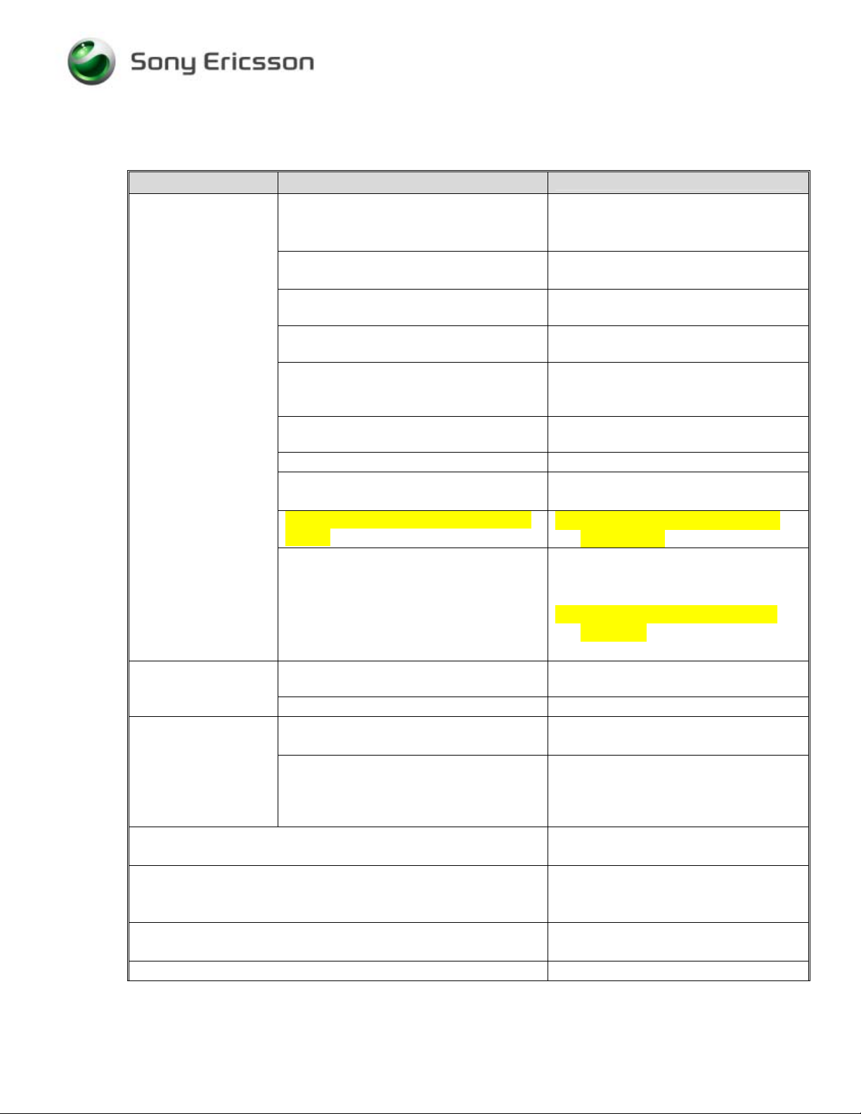
2 Repair Actions for Manual Test Failures
Failure Failure Symptom
2.1 Power On / Off
2.2 Software Flash
2.3 Charging
2.4 Hands-Free connection (PHF)
2.5 SIM
2.6 Charging indicator (RED LED)
2.7 Display
Current draw when powered off
Current draw greater than 300 mAmps
Hangs at gray display. Will not start
flashing • B300
Hangs at gray display. Will start
flashing, but fails after some percentage • No Repair Action
Some current draw when pressing power
key, but current returns to 0 when power
key is released
Powers on automatically when battery is
installed
Powers On BUT will not power off
Will not power on AND will not flash
Powers off at random and hangs at gray
display
Other symptoms
Phone powers on instead of starting
flash • N602, V604, N800
Other symptoms
Charging from power outlet
Charging from computer via USB
Measure V807 from pin 1 to pin 3 with
positive lead on pin 1
VDC should equal 0.20 to 0.23.
Repair Action
• V809
• N1401
• N1400
• N702
• N1400
• L800
• V404
• V400
• N1301
• N1303
• Remove C55 from the FPC. Do
not replace it.
• Replace X800 if damaged
• Replace X2490 if damaged
• Replace X2590 if damaged
• N1200 (remove R1205. Do not
replace it.)
• N702
• No Repair Action
• V802, V805
• N702
• If VDC is outside of range, then
replace V807
• N800
• N700
• N702, N1100
• Replace X701 if damaged
• N1401
• N702
• Replace X2490 if damaged
• V402
• Replace X2590 if damaged
4/000 21-2/FEA 209 544/594 D
©
Sony Ericsson Mobile Communications AB
3(7)
Page 4

Trouble Shooting Guide, Electrical
Failure Failure Symptom
2.8 Illumination
(Backlight or
LEDs)
All three sections are dark: LCD, Upper
Keys, And Lower Keys
Note: The LCD displays text, but there
Repair Action
• Replace V803 or L801 if out of
range. Also replace V804 before
powering the phone on.
• V808
is no light.
Measure V803 with positive lead on
Anode. VDC should equal 0.16 to 0.18.
Measure resistance across L801.
Resistance should be 1.0 to 2.0 Ohms.
Only two sections are dark: LCD and
Upper Keys
Only one section is dark: Upper Keys
• Replace X2490 if damaged
• Replace X2590 if damaged
• Replace X2590 if damaged
• V500
Only one section is dark: Lower Keys
• Replace X400 if damaged
• V808
2.9 Upper (rocker)
Keypad Keys
Center Key Only fails. Measure V400
resistance from pins 1 or 2 to pin 3.
Up, Down, Left, or Right fail.
Measure V401 resistance from pins 1 or
• If pins 1 or 2 are shorted to 3,
replace V400
• If pins 1 or 2 are shorted to 3,
replace V401
2 to pin 3. Pin 1 should be shorted to
pin2, but neither should be shorted to pin
3.
Other upper keypad failures
• Replace X2490 if damaged
• Z400
2.10 Lower (main) Keypad Keys
• Replace X400 if damaged
• Replace X900, X901 if damaged
• Z400
2.11 Volume Up
Key
Measure V400 resistance from pins 1 or
2 to pin 3. Pin 1 should be shorted to
pin2, but neither should be shorted to pin
• If pins 1 or 2 are shorted to 3,
replace V400
• Replace X2490 if damaged
3.
2.12 Volume Down Key
2.13 Camera Key
2.14 Lock key
2.15 On/Off key
2.16 Gaming (A and B) Keys
2.17 Media Player Key
2.18 Vibrator
• Replace X2490 if damaged
• Replace X2490 if damaged
• Replace X2490 if damaged
• Replace X2490 if damaged
• Replace X2490 if damaged
• Replace X2490 if damaged
• V700
• N702
2.19 Earphone (Speaker)
• X2490 if damaged
• N702
2.20 Polyphonic RIGHT (speaker A) (speaker phone)
• Replace X3250. X3251 if damaged
• V1100, V1101
• N1100
• N702
4/000 21-2/FEA 209 544/594 D
©
Sony Ericsson Mobile Communications AB
4(7)
Page 5

Trouble Shooting Guide, Electrical
Failure Failure Symptom
2.21 Polyphonic LEFT (speaker B)
2.22 Polyphonic BOTH
2.23 Microphone
2.24 Real Time Clock
2.25 Camera
2.26 Camera Flash
2.27 Flip Sensor
2.28 IR
2.29 Bluetooth
2.30 FM Radio
Repair Action
• Replace X3260 if damaged
• V1102, V1103
• N1100
• N702
• N1100
• N702
• Replace X2490 if damaged
• Z700
• N702
• B300
• Replace X2510 if damaged
• N500
• N702
• V506
• V500
• N501
• Replace X2590 if damaged
• D201
• N1200 (remove R1205. Do not
replace it.)
• N702
• N1102
• N1101
3 Repair Actions for Go/No Go Test Failures
Failure Repair Action
Fails any part of Go/No Go testing
Fails Go/No Go test, but passes calibration
Fails Go/No Go test after passing calibration
4/000 21-2/FEA 209 544/594 D
©
Sony Ericsson Mobile Communications AB
• run the calibration routine
• replace the antenna
• check X1301 for damage and replace if
necessary
• rerun the phone through Go/No Go
testing
• change X1300 and retest
5(7)
Page 6

Trouble Shooting Guide, Electrical
4 Repair Actions for Calibration Routine Failures
4.1 GSM 850, 900, 1800, or 1900
The variable F in the table below will be replaced by one of the different frequencies (GSM850,
GSM900, etc.).
Routine Repair Action
F_Calibrate_RXVCO
• N1303
F_Calibrate_TXVCO
F_Calibrate_TXCHVCO
F_Check_Output_Power
F_Calculate_POWTX_Value
Calibrate_VCXO
F_Measure_Multiframe
F_RSSI_Calibration
4.2 EDGE 850, 900, 1800, or 1900
The variable F in the table below will be replaced by one of the different frequencies (EDGE850,
EDGE900, etc.).
• N1303
• N1303
• N1400
• X1300
• N1304
• N1400
• N1301
• N1400
• N1304
• N1303
• N1304
The variable X in the table below will be replaced by one of the different levels (1, 2, or 3).
Routine Repair Action
F_Check_Output_Power
F_Get_POWTX_Value_For_PLX
F_Calibrate_VGAGAINX
F_Calibrate_PowerX
4/000 21-2/FEA 209 544/594 D
©
Sony Ericsson Mobile Communications AB
• N1400
• N1400
• N1400
• N1303
• N1400
• N1303
6(7)
Page 7

Trouble Shooting Guide, Electrical
5 Revision History
Rev. Date Changes / Comments
A 2005-Oct-17 Initial Release
B 2006-Feb-07 Added L801 and restructured Illumination section.
Removed Z400 from Lower Keypad LEDs. It should only be in the Lower
Keypad Keys section.
C 2006-Mar-14 Corrected measurement instruction for V807. Positive lead should be on pin 1
instead of pin 3.
D 2006-May-05 Added N1200 to Bluetooth and Power sections.
Added C55 removal to Power section.
Added V804 to Backlight section.
4/000 21-2/FEA 209 544/594 D
©
Sony Ericsson Mobile Communications AB
7(7)
 Loading...