

Page 1

Working Instruction, Mechanical
Working Instruction, Mechanical
Applicable for W595
CONTENTS
1 Introduction .............................................................................. 3
1.1 Equipment ................................................................................. 5
1.2 General cautions ...................................................................... 6
1.3 Adhesives ................................................................................. 6
2 Disassembly ............................................................................. 7
2.1 Overview ................................................................................... 7
2.1.1 Battery Cover and Battery ..................................................... 8
2.1.2 Deco Plate ............................................................................. 9
2.1.3 Front Cover Assy ................................................................. 10
2.1.4 Main Keyboard .................................................................... 11
2.1.5 Rear Cover .......................................................................... 12
2.1.6 Top and Bottom Cap ........................................................... 14
2.1.7 Earspeaker, Display and PBA Navigation ........................... 15
2.1.8 Frame Assy ......................................................................... 19
2.1.9 Hinge ................................................................................... 20
3 Replacements ......................................................................... 21
3.1 Battery Cover and Battery ..................................................... 22
3.2 Deco Plate ............................................................................... 22
3.3 Front Cover Assy ................................................................... 22
3.4 Main Keyboard ........................................................................ 22
3.5 Rear Cover .............................................................................. 22
3.6 Top and Bottom Cap .............................................................. 22
3.7 Earspeaker, Display and PBA Navigation ............................ 22
3.8 Frame Assy ............................................................................. 23
3.9 Hinge ....................................................................................... 23
3.9.1 Camera Assy ....................................................................... 24
3.9.2 Co-Brand ............................................................................. 26
3.9.3 Dust Gasket Hinge .............................................................. 27
3.9.4 Gasket Camera ................................................................... 27
3.9.5 Gasket Hinge....................................................................... 28
3.9.6 Gasket Microphone ............................................................. 28
3.9.7 Gasket Speaker Bottom ...................................................... 29
3.9.8 Gasket Speaker Top ........................................................... 29
3.9.9 Half to Half FPC .................................................................. 30
1215-7363 Rev 5
Company Internal
© Sony Ericsson Mobile Communi cat i ons AB
Page 2

Working Instruction, Mechanical
3.9.10 Keyboard Navigation ........................................................... 32
3.9.11 Light Guide Navi Keyboard ................................................. 33
3.9.12 Light Guide Main Keyboard ................................................. 34
3.9.13 Loudspeaker Bottom ........................................................... 35
3.9.14 Loudspeaker Top ................................................................ 36
3.9.15 Main Window ....................................................................... 37
3.9.16 PBA Main Keyboard FPC .................................................... 38
3.9.17 Tape Main Keyboard LED ................................................... 40
3.9.18 Tape Navigation LED .......................................................... 41
3.9.19 Tape Navigation LED middle ............................................... 41
3.9.20 Volume Key ......................................................................... 42
3.9.21 Walkman Key ...................................................................... 42
3.10 Liquid Indicator ...................................................................... 43
3.11 Core Unit Label ....................................................................... 44
4 Reassembly ............................................................................ 45
4.1 Overview ................................................................................. 46
4.1.1 Hinge ................................................................................... 47
4.1.2 Frame Assy ......................................................................... 48
4.1.3 Earspeaker, Display and PBA Navigation ........................... 49
4.1.4 Top and Bottom Cap ........................................................... 54
4.1.5 Rear Cover .......................................................................... 55
4.1.6 Main Keyboard .................................................................... 57
4.1.7 Front Cover Assy ................................................................. 58
4.1.8 Deco Plate ........................................................................... 59
4.1.9 Battery Cover and Battery ................................................... 60
5 Revision History ..................................................................... 61
1215-7363 Rev 5
Company Internal
2(61)
© Sony Ericsson Mobile Communi cat i ons AB
Page 3
Working Instruction, Mechanical
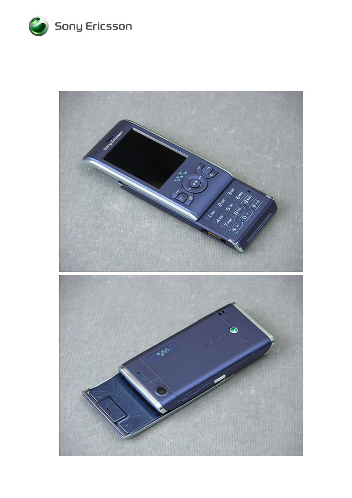
1 Introduction
W595
1215-7363 Rev 5
Company Internal
3(61)
© Sony Ericsson Mobile Communi cat i ons AB
Page 4
Working Instruction, Mechanical
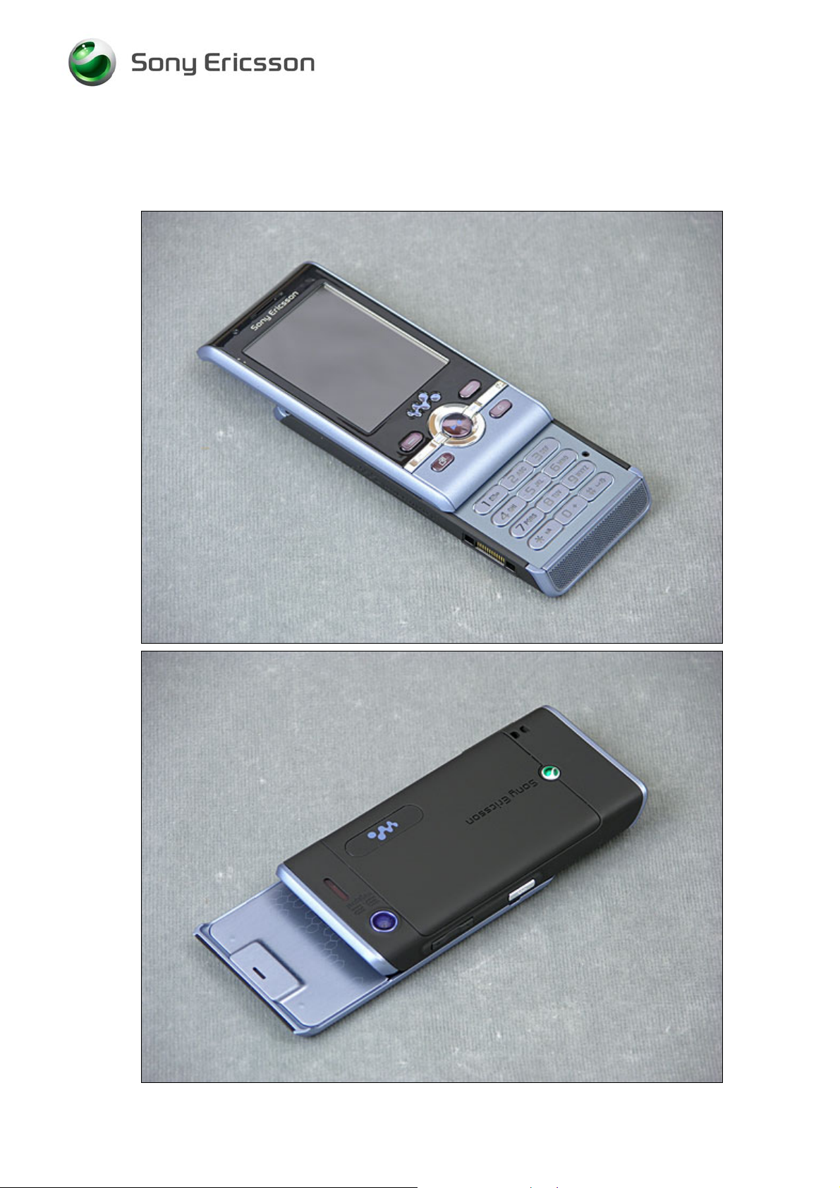
W595s
1215-7363 Rev 5
Company Internal
4(61)
© Sony Ericsson Mobile Communi cat i ons AB
Page 5
Working Instruction, Mechanical
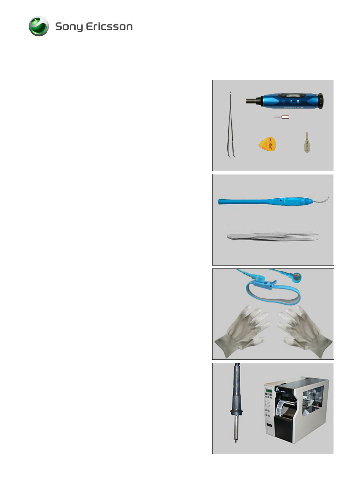
1.1 Equipment
SPECIAL TOOLS
• NTZ 112 459 Torque screwdriver (or equivalent)
• 1222-3513 Bits (PH00)
• NTZ 112 302/2 Front opening tool
• NTZ 112 521 Flex film assembly tool
• NTZ 112 590 Guitar pick
STANDARD TOOLS
Standard tools have to be locally purchased
• Dentist hook
• ESD tweezers
OTHER EQUIPMENT
• ESD wristband
• ESD gloves
LABEL EQUIPMENT
The following special equipment is required when replacing
or installing a new label:
• Hot air flow solder station
• Zebra printer connected to computer
1215-7363 Rev 5
Company Internal
© Sony Ericsson Mobile Communi cat i ons AB
5(61)
Page 6

Working Instruction, Mechanical
1.2 General cautions
The following cautions are considered to be generic for all phone models and will not be repeated in
the Disassembly, Replacements and Reassembly sections:
WITCH OFF THE PHONE AND REMOVE ANY MEMORY STICK BEFORE THE START OF THE DISASSEMBLY!
• S
EEP ALL CONTACT SURFACES CLEAN!
• K
E CAREFUL WHEN USING TOOLS LIKE THE DENTIST HOOK, TWEEZERS, OPENING TOOLS, GUITAR PICK
• B
ETC. TO AVOID SCRATCHES OR DAMAGES TO THE EXTERIOR AND INTERIOR PARTS OF THE PHONE!
• B
E CAREFUL NOT TO DAMAGE ANY CONTACT SPRINGS!
EMEMBER TO REMOVE THE PROTECTION FOILS ON NEW PARTS SUCH AS THE FRONT COVER AND LCD!
• R
EVER TOUCH THE DISPLAY GLASS!
• N
SE AIR BLOW EQUIPMENT TO KEEP THE FRONT WINDOW AND DISPLAY MODULE DUST FREE!
• U
1.3 Adhesives
Use a dentist hook and/or the tweezers to remove old adhesives.
Clean the surface with isopropyl alcohol before attaching new adhesives.
1215-7363 Rev 5
Company Internal
6(61)
© Sony Ericsson Mobile Communi cat i ons AB
Page 7
Working Instruction, Mechanical
2 Disassembly
When you are going to replace a part being listed in Replacements, the instruction of that section
usually begins by directing you to this Disassembly section with a specification of the instructions
you have to carry out in order to disassemble the phone as far as needed before returning to
Replacements for the actual replacement.
REPLACEMENTS
Start
Contents
page
DISASSEMBLY
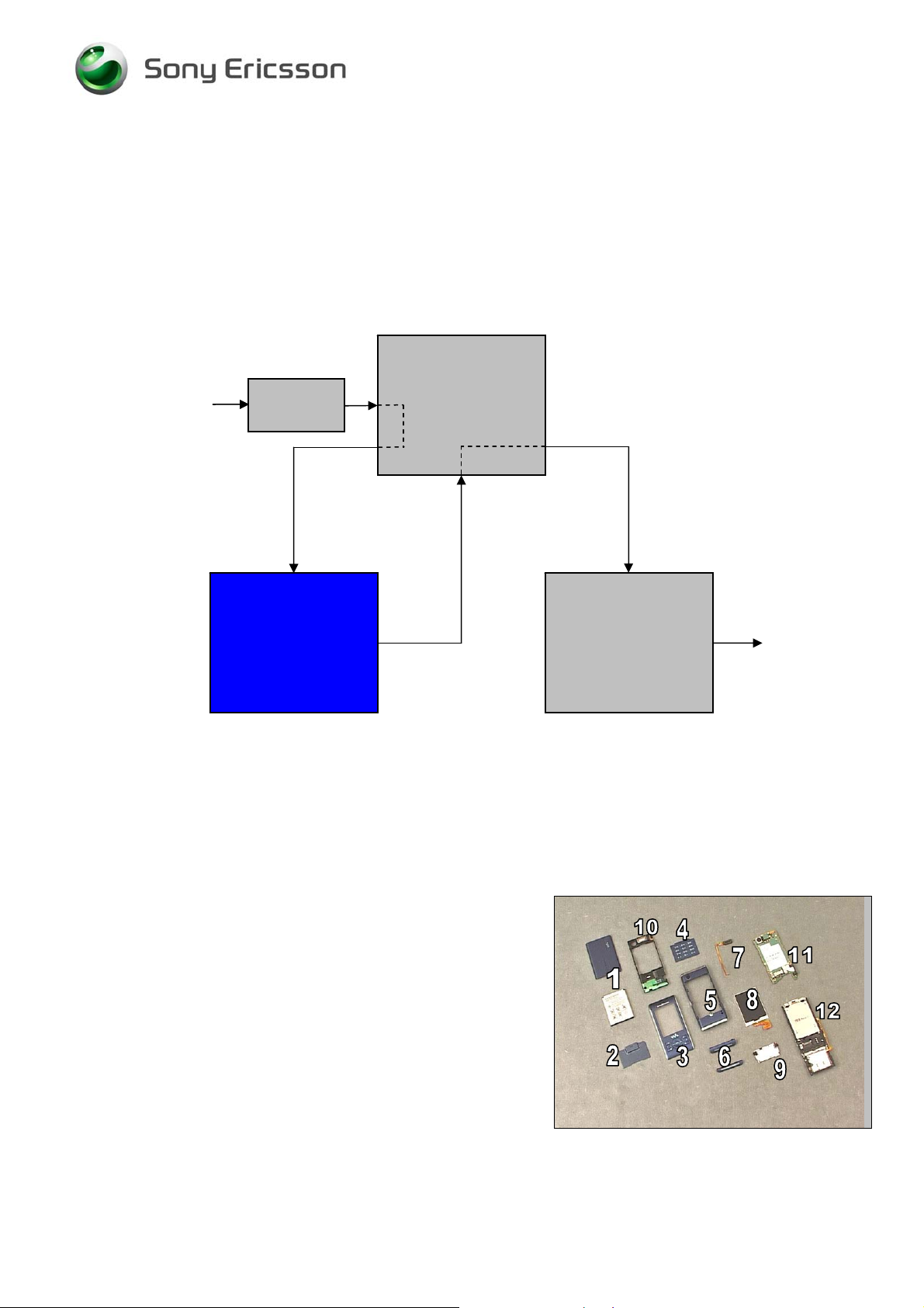
2.1 Overview
REASSEMBLY
Done
The disassembly is done in the following order:
1. Battery Cover and Battery
2. Deco Plate
3. Front Cover Assy
4. Main Keyboard
5. Rear Cover
6. Top and Bottom Cap
7. Earspeaker
8. Display
9. PBA Navigation
10. Frame Assy
11. Main PBA
12. Hinge
1215-7363 Rev 5
Company Internal
© Sony Ericsson Mobile Communi cat i ons AB
7(61)
Page 8
Working Instruction, Mechanical
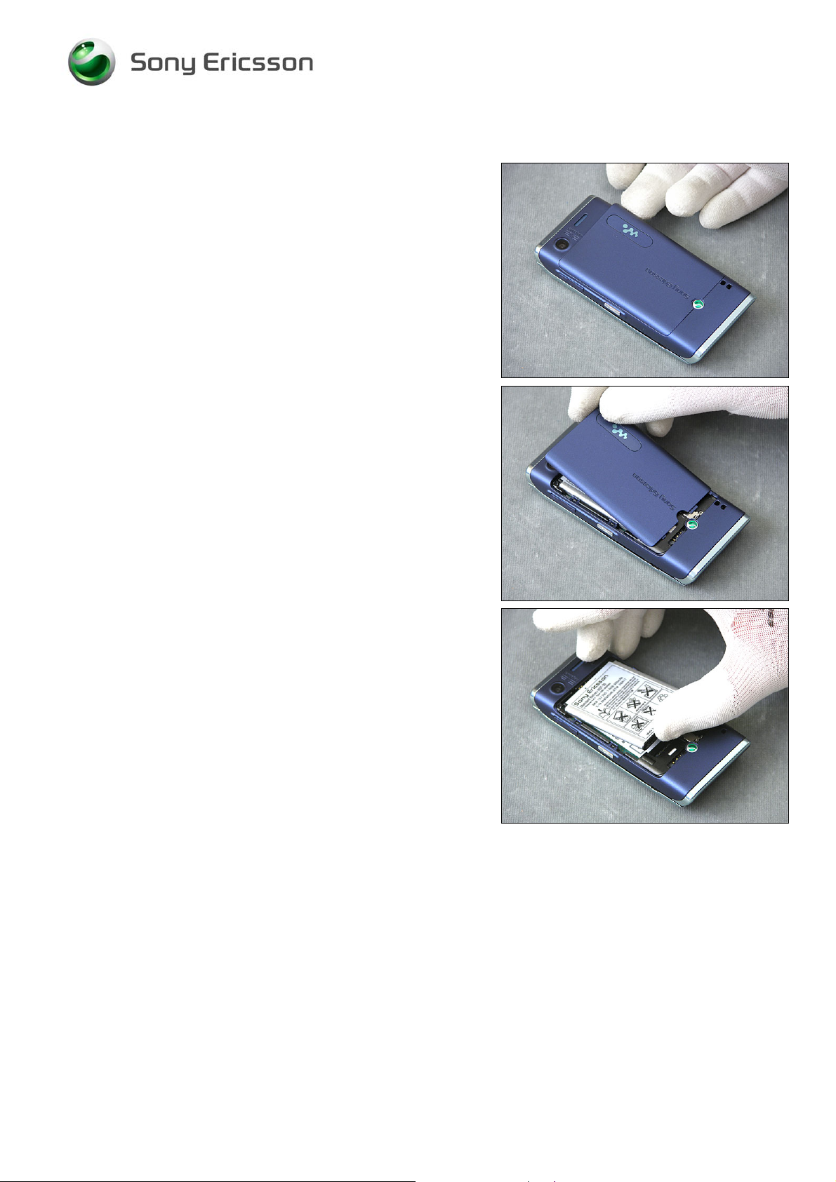
2.1.1 Battery Cover and Battery
Remove the Battery Cover.
Remove the Battery.
1215-7363 Rev 5
Company Internal
8(61)
© Sony Ericsson Mobile Communi cat i ons AB
Page 9
Working Instruction, Mechanical
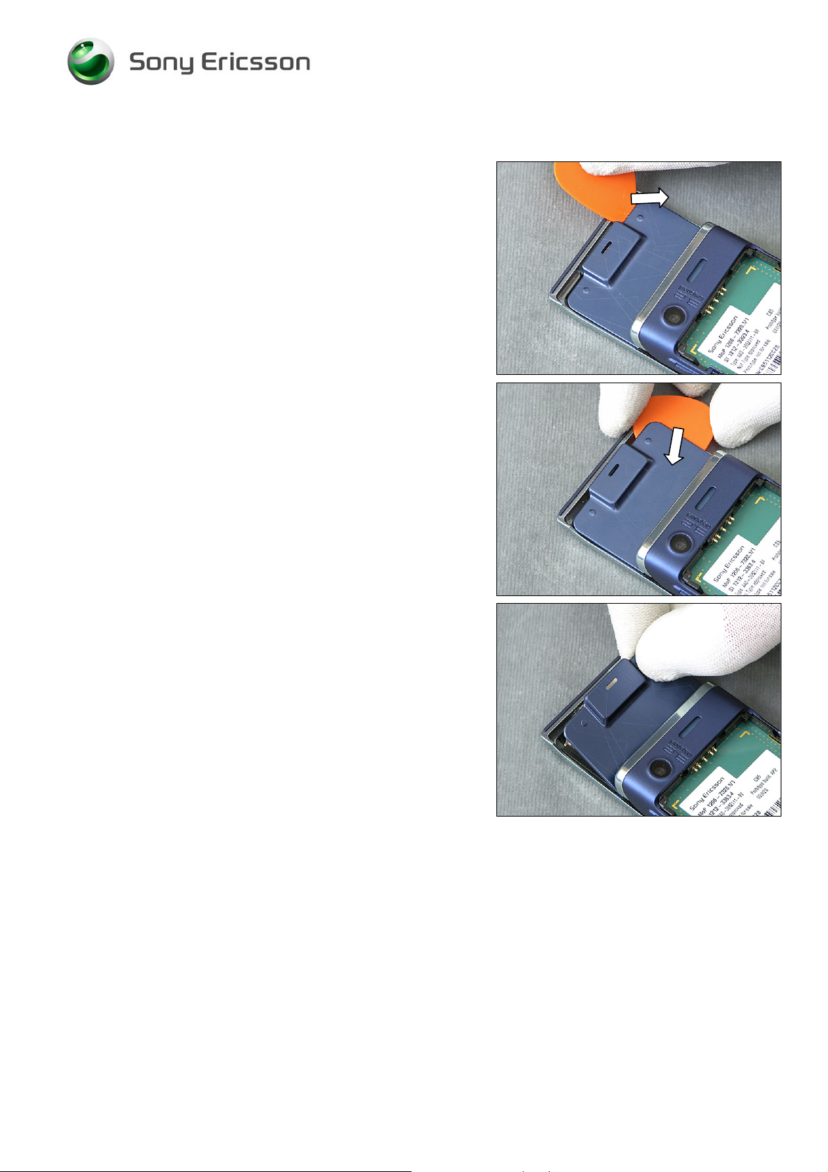
2.1.2 Deco Plate
Release the Deco Plate with a guitar pick.
Remove the Deco Plate.
1215-7363 Rev 5
Company Internal
9(61)
© Sony Ericsson Mobile Communi cat i ons AB
Page 10
Working Instruction, Mechanical
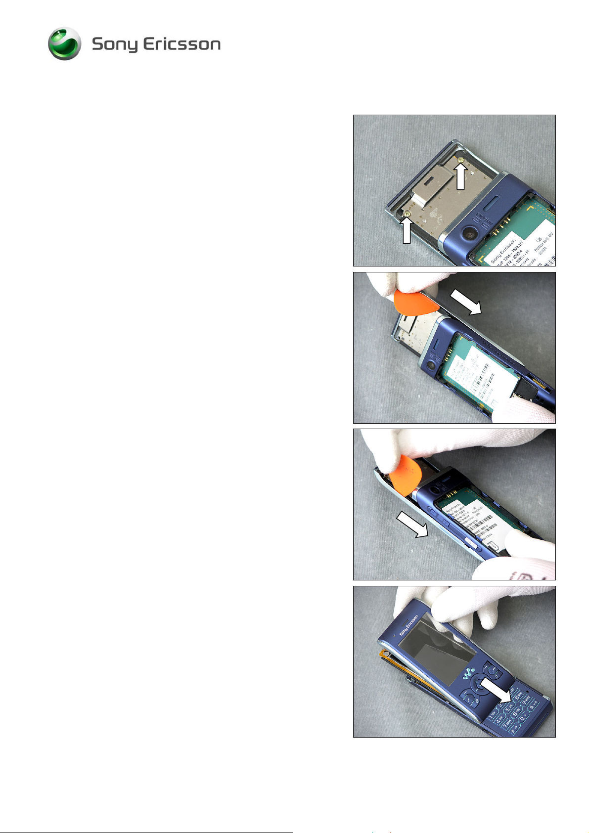
2.1.3 Front Cover Assy
Remove the two screws (PH00).
Use a guitar pick and slide along the side to release the
snap hooks.
Slide along the other side.
Remove the Front Cover.
1215-7363 Rev 5
Company Internal
© Sony Ericsson Mobile Communi cat i ons AB
10(61)
Page 11
Working Instruction, Mechanical
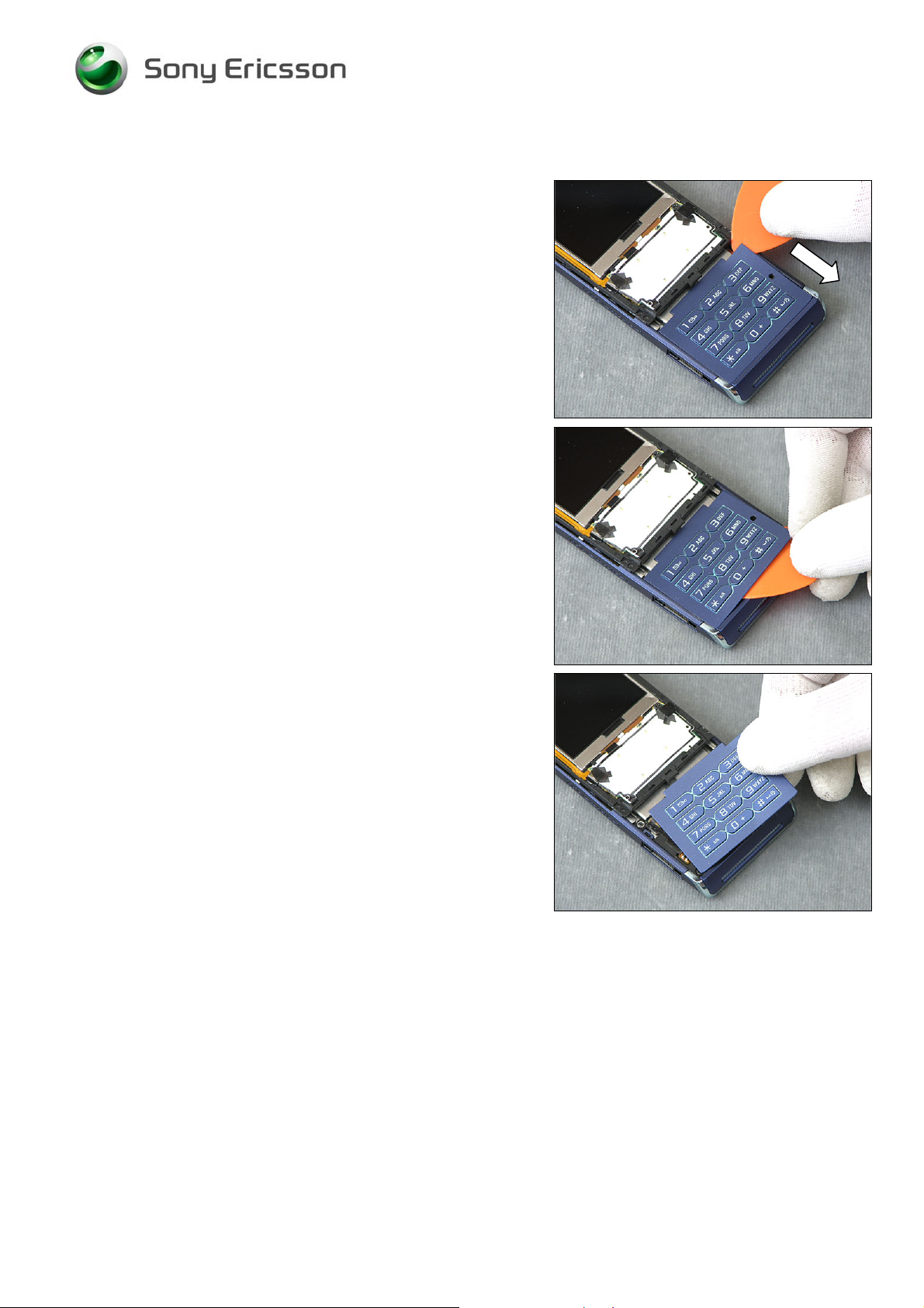
2.1.4 Main Keyboard
Release the Main Keyboard with a guitar pick.
Be careful with the Light Guide underneath.
Remove the Main Keyboard.
1215-7363 Rev 5
Company Internal
11(61)
© Sony Ericsson Mobile Communi cat i ons AB
Page 12
Working Instruction, Mechanical
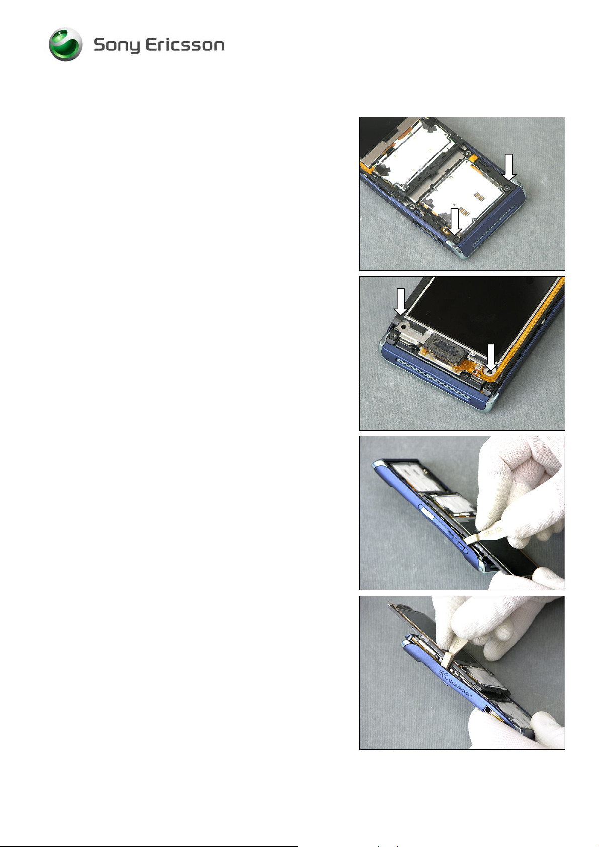
2.1.5 Rear Cover
Remove the two bottom screws (PH00).
Remove the two top screws (PH00).
Release the snap hooks along both sides with a front
opening tool.
1215-7363 Rev 5
Company Internal
12(61)
© Sony Ericsson Mobile Communi cat i ons AB
Page 13
Working Instruction, Mechanical
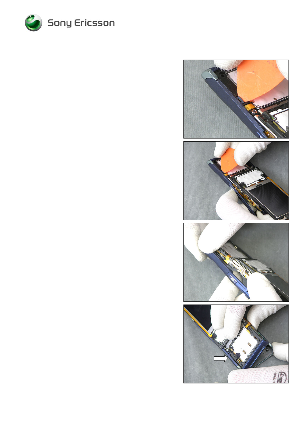
Rear Cover continue
Release the hook with a guitar pick.
Release the Rear Cover from the core unit.
Be careful with the hook.
1215-7363 Rev 5
Company Internal
© Sony Ericsson Mobile Communi cat i ons AB
13(61)
Page 14
Working Instruction, Mechanical
2.1.6 Top and Bottom Cap
Remove the Bottom Cap.
Unsnap the hooks on the Top cap.
Remove the Top Cap.
1215-7363 Rev 5
Company Internal
14(61)
© Sony Ericsson Mobile Communi cat i ons AB
Page 15
Working Instruction, Mechanical
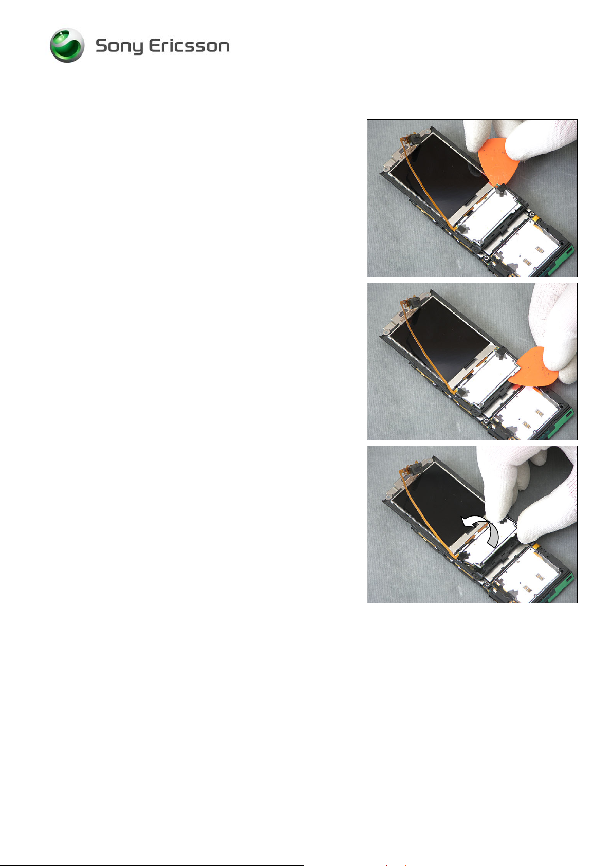
2.1.7 Earspeaker, Display and PBA Navigation
Remove the screw (PH00).
Release the Earspeaker with a guitar pick.
Slide along the Earspeaker fllex.
1215-7363 Rev 5
Company Internal
15(61)
© Sony Ericsson Mobile Communi cat i ons AB
Page 16
Working Instruction, Mechanical
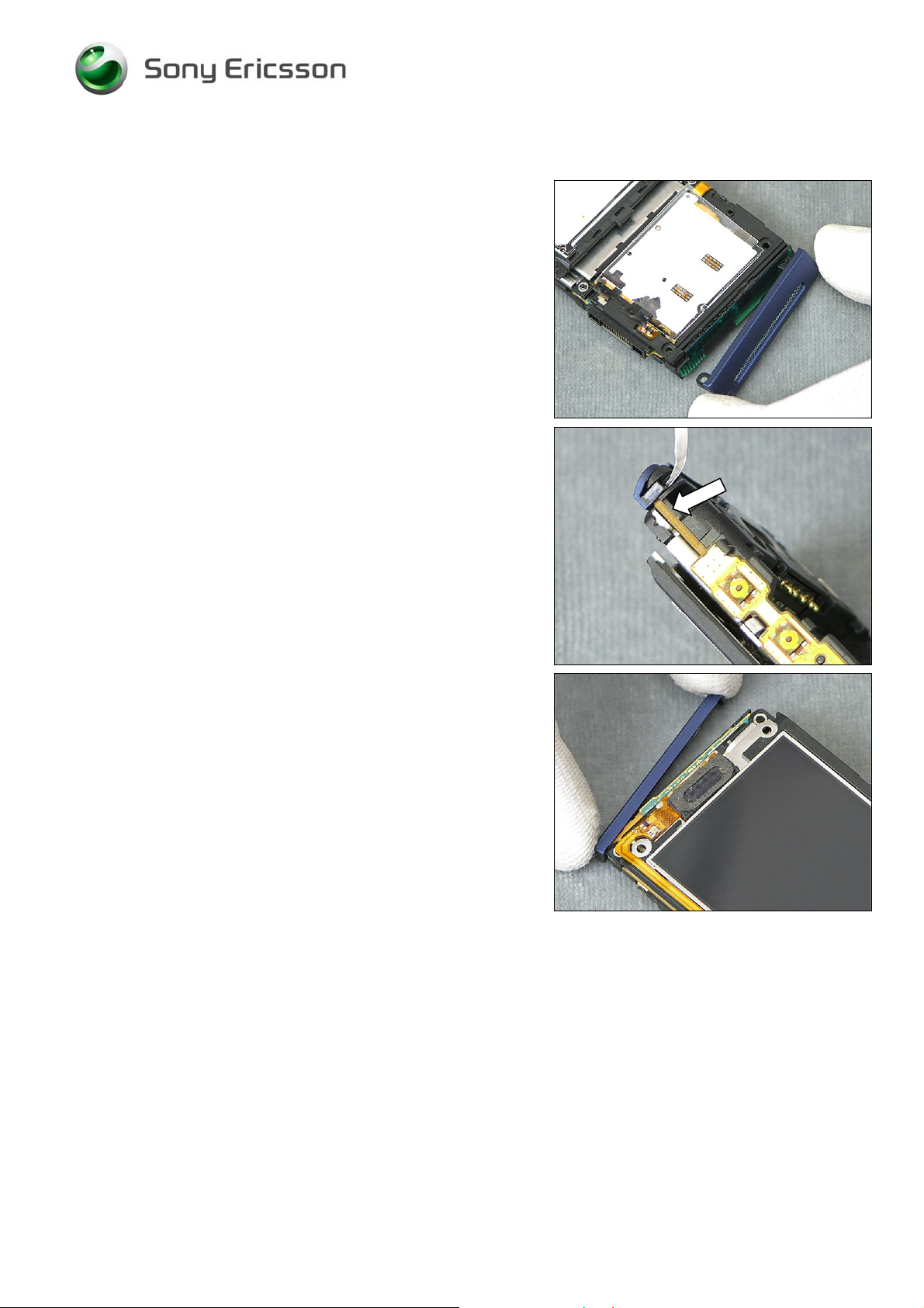
Earspeaker, Display and PBA Navigation continue
Release the PBA Navigation.
Turn over the PBA Navigation to reach the connectors.
1215-7363 Rev 5
Company Internal
16(61)
© Sony Ericsson Mobile Communi cat i ons AB
Page 17
Working Instruction, Mechanical
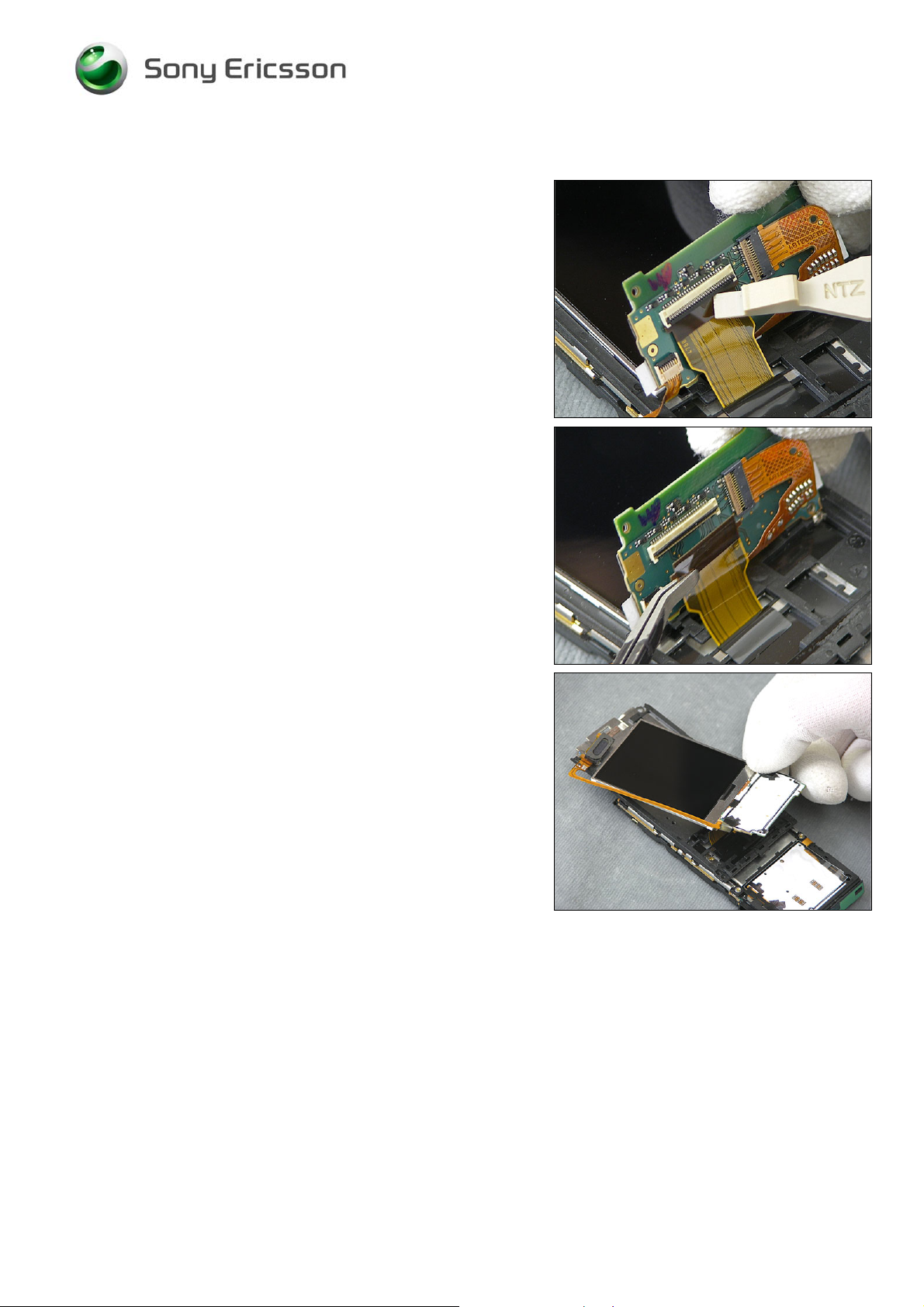
Earspeaker, Display and PBA Navigation continue
Open the connector carefully.
Remove the flex.
Remove the Earspeaker, Display and PBA Navigation.
1215-7363 Rev 5
Company Internal
17(61)
© Sony Ericsson Mobile Communi cat i ons AB
Page 18
Working Instruction, Mechanical
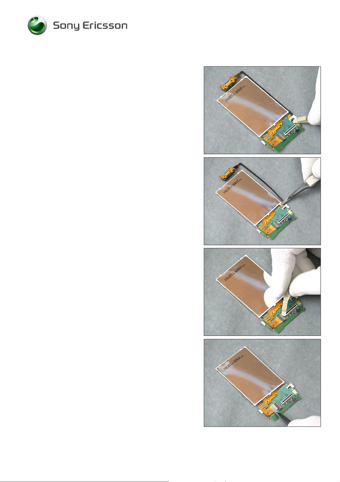
Earspeaker, Display and PBA Navigation continue
Open the Earspeaker connector carefully.
Remove the Earspeaker flex.
Open the Display connector carefully.
Remove the Display flex.
1215-7363 Rev 5
Company Internal
© Sony Ericsson Mobile Communi cat i ons AB
18(61)
Page 19
Working Instruction, Mechanical
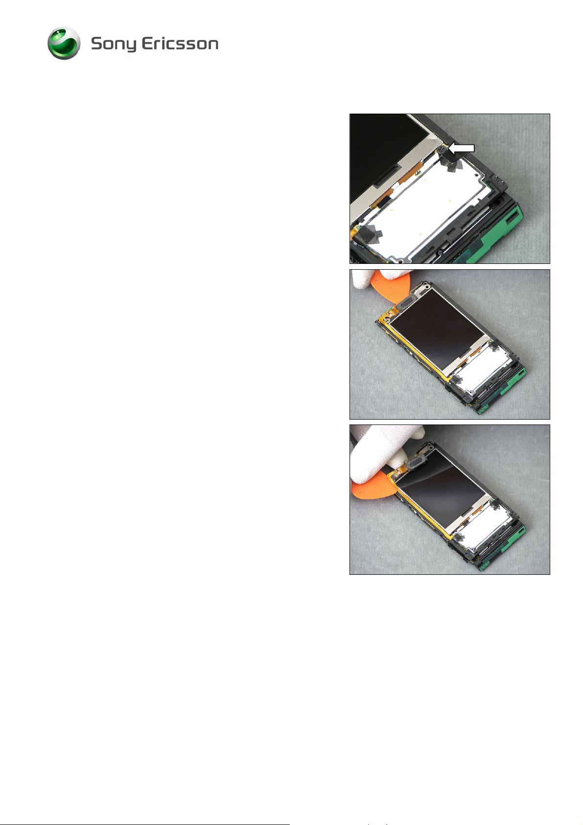
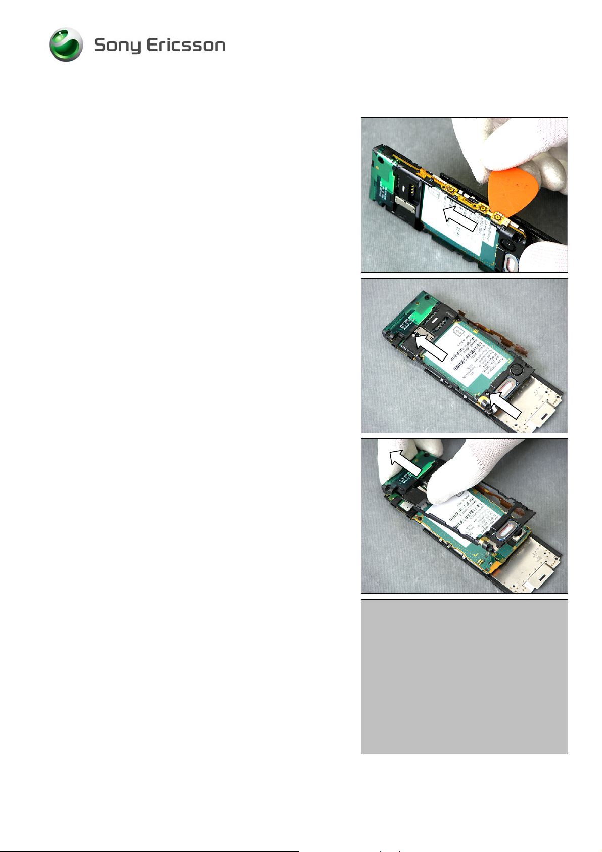
2.1.8 Frame Assy
Slide carefully along the side button flex with a guitar pick to
release it from the hooks.
Remove the two screws (PH00).
Remove the Frame Assy.
1215-7363 Rev 5
Company Internal
19(61)
© Sony Ericsson Mobile Communi cat i ons AB
Page 20

Working Instruction, Mechanical
2.1.9 Hinge
Remove the two screws (PH00).
Lift up the Main PBA.
Open the connector carefully.
Remove the Main PBA Keyboard FPC and the Main PBA.
1215-7363 Rev 5
Company Internal
© Sony Ericsson Mobile Communi cat i ons AB
20(61)
Page 21

Working Instruction, Mechanical
3 Replacements
Search for the part to be replaced on the Contents page and go to that instruction to be found in this
Replacements section.
The instruction usually begins by directing you to the Disassembly section with a specification of the
instructions you have to carry out in order to disassemble the phone as far as needed before the
actual replacement.
Go back to this Replacements section and carry out the instruction.
The instruction usually ends by directing you to the Reassembly section with a specification of the
instructions you have to carry out in order to reassemble the phone.
REPLACEMENTS
Start
Contents
page
DISASSEMBLY REASSEMBLY
Done
1215-7363 Rev 5
Company Internal
21(61)
© Sony Ericsson Mobile Communi cat i ons AB
Page 22

Working Instruction, Mechanical
3.1 Battery Cover and Battery
Follow the 2.1.1 Disassembly instructions
Prepare the new Battery Cover.
Follow the 4.1.9 Reassembly instructions
3.2 Deco Plate
Follow the 2.1.1 – 2.1.2 Disassembly instructions
Prepare the new Deco Plate.
Follow the 4.1.8 – 4.1.9 Reassembly instructions
3.3 Front Cover Assy
Follow the 2.1.1 – 2.1.3 Disassembly instructions
Prepare the new Front Cover Assy.
Follow the 4.1.7 – 4.1.9 Reassembly instructions
3.4 Main Keyboard
Follow the 2.1.1 – 2.1.4 Disassembly instructions
Prepare the new Main Keyboard.
Follow the 4.1.6 – 4.1.9 Reassembly instructions
3.5 Rear Cover
Follow the 2.1.1 – 2.1.5 Disassembly instructions
Prepare the new Rear Cover.
Follow the 4.1.5 – 4.1.9 Reassembly instructions
3.6 Top and Bottom Cap
Follow the 2.1.1 – 2.1.6 Disassembly instructions
Prepare the new Top or/and Bottom Cap.
Follow the 4.1.4 – 4.1.9 Reassembly instructions
3.7 Earspeaker, Display and PBA Navigation
Follow the 2.1.1 – 2.1.3 and 2.1.7 Disassembly instructions
Prepare the new Earspeaker, Display or/and PBA Navigation.
Follow the 4.1.3 and 4.1.7 – 4.1.9 Reassembly instructions
1215-7363 Rev 5
Company Internal
22(61)
© Sony Ericsson Mobile Communi cat i ons AB
Page 23

Working Instruction, Mechanical
3.8 Frame Assy
Follow the 2.1.1 – 2.1.8 Disassembly instructions
Prepare the new Frame Assy.
Follow the 4.1.2 – 4.1.9 Reassembly instructions
3.9 Hinge
Follow the 2.1.1 – 2.1.9 Disassembly instructions
Prepare the new Hinge.
Follow the 4.1.1 – 4.1.9 Reassembly instructions
1215-7363 Rev 5
Company Internal
23(61)
© Sony Ericsson Mobile Communi cat i ons AB
Page 24

Working Instruction, Mechanical
3.9.1 Camera Assy
REMOVAL
Follow the 2.1.1 – 2.1.9 Disassembly instructions.
Lift the Shield Camera Can Lid with a dentist hook.
Remove the Shield Camera Can Lid.
Open the connector carefully.
Remove the Camera.
1215-7363 Rev 5
Company Internal
© Sony Ericsson Mobile Communi cat i ons AB
24(61)
Page 25

Working Instruction, Mechanical
Camera Assy continue
INSTALLATION
Replace the new Camera flex.
Close the connector gently.
Mount the Shield Camera Can Lid.
Press to attach.
Follow the 4.1.1 – 4.1.9 Reassembly instructions.
1215-7363 Rev 5
Company Internal
© Sony Ericsson Mobile Communi cat i ons AB
25(61)
Page 26

Working Instruction, Mechanical
3.9.2 Co-Brand
REMOVAL
Follow the 2.1.1 Disassembly instructions.
Remove the Co-Brand with a dentist hook.
INSTALLATION
Mount a new Co-Brand.
Press to attach.
Follow the 4.1.9 Reassembly instructions.
1215-7363 Rev 5
Company Internal
26(61)
© Sony Ericsson Mobile Communi cat i ons AB
Page 27

Working Instruction, Mechanical
3.9.3 Dust Gasket Hinge
REMOVAL
Follow the 2.1.1 – 2.1.9 Disassembly instructions.
Remove the Dust Gasket Hinge.
Clean the Rear Cover with isopropyl alcohol.
INSTALLATION
Mount a new Dust Gasket Hinge. Press to attach.
Follow the 4.1.1 – 4.1.9 Reassembly instructions.
3.9.4 Gasket Camera
REMOVAL
Follow the 2.1.1 – 2.1.5 Disassembly instructions.
Remove the Gasket Camera.
Clean the Rear Cover with isopropyl alcohol.
INSTALLATION
Mount a new Gasket Camera. Press to attach.
Follow the 4.1.5 – 4.1.9 Reassembly instructions.
1215-7363 Rev 5
Company Internal
© Sony Ericsson Mobile Communi cat i ons AB
27(61)
Page 28

Working Instruction, Mechanical
3.9.5 Gasket Hinge
REMOVAL
Follow the 2.1.1 – 2.1.9 Disassembly instructions.
Remove the Gasket Hinge.
Clean the Rear Cover with isopropyl alcohol.
INSTALLATION
Mount a new Gasket Hinge. Press to attach.
Follow the 4.1.1 – 4.1.9 Reassembly instructions.
3.9.6 Gasket Microphone
REMOVAL
Follow the 2.1.1 – 2.1.9 Disassembly instructions.
Remove the Gasket Microphone.
INSTALLATION
Mount a new Gasket Microphone.
Follow the 4.1.1 – 4.1.9 Reassembly instructions.
1215-7363 Rev 5
Company Internal
© Sony Ericsson Mobile Communi cat i ons AB
28(61)
Page 29

Working Instruction, Mechanical
3.9.7 Gasket Speaker Bottom
REMOVAL
Follow the 2.1.1 – 2.1.6 and 2.1.8 Disassembly instructions.
Remove the Gasket Speaker Bottom.
Clean the Frame Assy with isopropyl alcohol.
INSTALLATION
Mount a new Gasket Speaker Bottom with a par of
tweezers. Press with your finger to attach.
Follow the 4.1.2 and 4.1.4 – 4.1.9 Reassembly instructions.
3.9.8 Gasket Speaker Top
REMOVAL
Follow the 2.1.1 – 2.1.5 Disassembly instructions.
Remove the Gasket Speaker Top.
Clean the Rear Cover with isopropyl alcohol.
INSTALLATION
Mount a new Gasket Speaker Top.
Follow the 4.1.5 – 4.1.9 Reassembly instructions.
1215-7363 Rev 5
Company Internal
© Sony Ericsson Mobile Communi cat i ons AB
29(61)
Page 30

Working Instruction, Mechanical
3.9.9 Half to Half FPC
REMOVAL
Follow the 2.1.1 – 2.1.9 Disassembly instructions.
Lift up the Half to Half FPC from the Shield Can Lid with a
par of tweezers.
Open the connector carefully.
Remove the Half to Half FPC.
Remove the HtH Adhesive with a dentist hook.
Clean the Shield Can Lid with isopropyl alcohol.
1215-7363 Rev 5
Company Internal
© Sony Ericsson Mobile Communi cat i ons AB
30(61)
Page 31

Working Instruction, Mechanical
Half to Half FPC continue
INSTALLATION
Replace a new HtH Adhesive.
Install the Half to Half FPC in the connector.
Close the connector gently.
Mount the Half to Half FPC to the HtH Adhesive.
Press to attach.
Follow the 4.1.1 – 4.1.9 Reassembly instructions.
1215-7363 Rev 5
Company Internal
31(61)
© Sony Ericsson Mobile Communi cat i ons AB
Page 32

Working Instruction, Mechanical
3.9.10 Keyboard Navigation
REMOVAL
Follow the 2.1.1 – 2.1.3 Disassembly instructions.
Remove the Keyboard Navigation.
INSTALLATION
Mount a new Keyboard Navigation.
Follow the 4.1.7 – 4.1.9 Reassembly instructions.
1215-7363 Rev 5
Company Internal
32(61)
© Sony Ericsson Mobile Communi cat i ons AB
Page 33

Working Instruction, Mechanical
3.9.11 Light Guide Navi Keyboard
REMOVAL
Follow the 2.1.1 – 2.1.3 Disassembly instructions and
the 3.9.17 Replacements instructions.
Remove the Light Guide Navi Keyboard with a guitar pick.
INSTALLATION
Mount a new Light Guide Navi Keyboard.
Press to attach.
Follow the 3.9.17 Replacements instructions and
the 4.1.7 - 4.1.9 Reassembly instructions.
1215-7363 Rev 5
Company Internal
33(61)
© Sony Ericsson Mobile Communi cat i ons AB
Page 34

Working Instruction, Mechanical
3.9.12 Light Guide Main Keyboard
REMOVAL
Follow the 2.1.1 – 2.1.4 Disassembly instructions and
the 3.9.18 Replacements instructions.
Remove the Light Guide Main Keyboard with a par of
tweezers.
INSTALLATION
Mount a new Light Guide Main Keyboard.
Press to attach.
Follow the 3.9.18 Replacements instructions and
the 4.1.6 - 4.1.9 Reassembly instructions.
1215-7363 Rev 5
Company Internal
34(61)
© Sony Ericsson Mobile Communi cat i ons AB
Page 35

Working Instruction, Mechanical
3.9.13 Loudspeaker Bottom
REMOVAL
Follow the 2.1.1 – 2.1.8 Disassembly instructions.
Remove the Loudspeaker Bottom with a dentist hook.
Remove the Adhesive Speaker Bottom with a dentist hook.
Clean the pit in the Frame Assy with isopropyl alcohol.
INSTALLATION
Mount a new Adhesive Speaker Bottom.
Mount a new Loudspeaker Bottom.
Notice that the pin on the Loudspeaker should be in the
right direction. Press to attach.
Follow the 4.1.2 – 4.1.9 Reassembly instructions.
1215-7363 Rev 5
Company Internal
35(61)
© Sony Ericsson Mobile Communi cat i ons AB
Page 36

Working Instruction, Mechanical
3.9.14 Loudspeaker Top
REMOVAL
Follow the 2.1.1 – 2.1.8 Disassembly instructions.
Remove the Loudspeaker Top with a dentist hook.
INSTALLATION
Mount a new Loudspeaker Top.
Notice that the pin on the Loudspeaker should be in the
right direction
Press to attach.
Follow the 4.1.2 – 4.1.9 Reassembly instructions.
1215-7363 Rev 5
Company Internal
36(61)
© Sony Ericsson Mobile Communi cat i ons AB
Page 37

Working Instruction, Mechanical
3.9.15 Main Window
REMOVAL
Follow the 2.1.1 – 2.1.3 Disassembly instructions.
Remove the Main Window from the Front Cover.
INSTALLATION
Mount a new Main Window.
Press to attach.
Remove the Protection Tape.
Follow the 4.1.7 – 4.1.9 Reassembly instructions.
1215-7363 Rev 5
Company Internal
© Sony Ericsson Mobile Communi cat i ons AB
37(61)
Page 38

Working Instruction, Mechanical
3.9.16 PBA Main Keyboard FPC
REMOVAL
Follow the 2.1.1 – 2.1.9 Disassembly instructions.
Release the tongue from the backside of the Hinge.
Push it through the Hinge.
Remove the PBA Main Keyboard FPC.
Remove the old Conductive adhesive.
There will be a new Conductive adhesive on the new
PBA Main Keyboard FPC.
1215-7363 Rev 5
Company Internal
© Sony Ericsson Mobile Communi cat i ons AB
38(61)
Page 39

Working Instruction, Mechanical
PBA Main Keyboard FPC continue
Remove the Adhesive Main Keyboard with a par of
tweezers. Clean with isopropyl alcohol.
INSTALLATION
Mount a new Adhesive Main Keyboard with a par of
tweezers.
Push the right tongue through the Hinge.
Push the left tongue through the Hinge.
Mount the new PBA Main Keyboard FPC on the Hinge.
1215-7363 Rev 5
Company Internal
© Sony Ericsson Mobile Communi cat i ons AB
39(61)
Page 40

Working Instruction, Mechanical
PBA Main Keyboard FPC continue
Mount the tongue.
Press to attach.
Follow the 3.9.12 Replacements instructions and
the 4.1.1 - 4.1.9 Reassembly instructions.
3.9.17 Tape Main Keyboard LED
REMOVAL
Follow the 2.1.1 – 2.1.4 Disassembly instructions.
Remove the Tape.
INSTALLATION
Mount a new Tape and press with your finger to attach.
Follow the 4.1.5 – 4.1.9 Reassembly instructions.
1215-7363 Rev 5
Company Internal
© Sony Ericsson Mobile Communi cat i ons AB
40(61)
Page 41

Working Instruction, Mechanical
3.9.18 Tape Navigation LED
REMOVAL
Follow the 2.1.1 – 2.1.3 Disassembly instructions.
Remove the Tape.
INSTALLATION
Mount a new Tape and press with your finger to attach.
Follow the 4.1.7 – 4.1.9 Reassembly instructions.
3.9.19 Tape Navigation LED middle
REMOVAL
Follow the 2.1.1 – 2.1.3 Disassembly instructions.
Remove the Tape.
INSTALLATION
Mount a new Tape and press with your finger to attach.
Follow the 4.1.7 – 4.1.9 Reassembly instructions.
1215-7363 Rev 5
Company Internal
© Sony Ericsson Mobile Communi cat i ons AB
41(61)
Page 42

Working Instruction, Mechanical
3.9.20 Volume Key
REMOVAL
Follow the 2.1.1 – 2.1.5 Disassembly instructions.
Remove the Volume Key.
INSTALLATION
Mount a new Volume Key.
Follow the 4.1.5 – 4.1.9 Reassembly instructions.
3.9.21 Walkman Key
REMOVAL
Follow the 2.1.1 – 2.1.5 Disassembly instructions.
Remove the Walkman Key.
INSTALLATION
Mount a new Walkman Key.
Follow the 4.1.5 – 4.1.9 Reassembly instructions.
1215-7363 Rev 5
Company Internal
© Sony Ericsson Mobile Communi cat i ons AB
42(61)
Page 43

Working Instruction, Mechanical
3.10 Liquid Indicator
INSPECTION
There is a Liquid Indicator located at the arrow.
REMOVAL
Follow the 2.1.1 – 2.1.8 Disassembly instructions.
Remove the old Liquid Indicator with a dentist hook.
INSTALLATION
Use a pair of tweezers to mount a new Liquid Indicator
on the Frame Assy.
Follow the 4.1.2 - 4.1.9 Reassembly instructions.
1215-7363 Rev 5
Company Internal
43(61)
© Sony Ericsson Mobile Communi cat i ons AB
Page 44

Working Instruction, Mechanical
3.11 Core Unit Label
Follow the 2.1.1 Disassembly instructions.
Read the old label and/or write the information into the
“Label make” program before removal.
Note the position of the label before removal.
Heat up the label by using hot air, if needed.
Carefully remove the label without causing scratches.
If there still are residues, clean the surface with isopropyl
alcohol.
Check that the proper label format is loaded in the Zebra
printer.
Write a new label by using the program “Label make” and
check that the printing is OK.
Take the new label and place it onto the frame as in the
adjacent picture.
NE LABEL ONLY IS ALLOWED!
O
Follow the 4.1.9 Reassembly instructions.
1215-7363 Rev 5
Company Internal
44(61)
© Sony Ericsson Mobile Communi cat i ons AB
Page 45

Working Instruction, Mechanical
4 Reassembly
After replacing a part being listed in Replacements, the instruction of that section usually ends by
directing you to this Reassembly section with a specification of the instructions you have to carry
out in order to reassemble the phone.
REPLACEMENTS
Start
Contents
page
DISASSEMBLY
REASSEMBLY
Done
1215-7363 Rev 5
Company Internal
45(61)
© Sony Ericsson Mobile Communi cat i ons AB
Page 46

Working Instruction, Mechanical
4.1 Overview
The disassembly is done in the following order:
1. Hinge
2. Main PBA
3. Frame Assy
4. PBA Navigation
5. Display
6. Earspeaker
7. Top and Bottom Cap
8. Rear Cover
9. Main Keyboard
10. Front Cover Assy
11. Deco Plate
12. Battery Cover and Battery
1215-7363 Rev 5
Company Internal
46(61)
© Sony Ericsson Mobile Communi cat i ons AB
Page 47

Working Instruction, Mechanical
4.1.1 Hinge
Install the Main PBA Keyboard FPC in the connector.
Close the connector gently.
Install the Half to Half FPC through the Hinge.
Install two new Screws Ph 1.6 x 3.0 with a torque
screwdriver at 12 Ncm (PH00 bit).
1215-7363 Rev 5
Company Internal
© Sony Ericsson Mobile Communi cat i ons AB
47(61)
Page 48

Working Instruction, Mechanical
4.1.2 Frame Assy
Mount the Frame Assy.
Press to attach.
Install two new Screws Ph 1.2 x 3.4 with a torque
screwdriver at 12 Ncm (PH00 bit).
If the PBA Main Keyboard FPC is reused - Clean the
Sidekey flex with isopropyl alcohol to remove the old
adhesive.
Mount a new Adhesive Sidekey FPC.
Mount the Sidekey flex with a par of tweezers.
Notice the hooks.
Press to attach.
1215-7363 Rev 5
Company Internal
48(61)
© Sony Ericsson Mobile Communi cat i ons AB
Page 49

Working Instruction, Mechanical
4.1.3 Earspeaker, Display and PBA Navigation
If the Earspeaker is reused - Clean the Earspeaker flex
with isopropyl alcohol to remove the old adhesive.
Mount a new Adhesive Earsp FPC Top and a new Adhesive
Earsp FPC Bottom.
If the Earspeaker is reused - remove the Adhesive
Earspeaker.
If the Earspeaker is reused - mount a new Adhesive
Earspeaker.
1215-7363 Rev 5
Company Internal
49(61)
© Sony Ericsson Mobile Communi cat i ons AB
Page 50

Working Instruction, Mechanical
Earspeaker, Display and PBA Navigation continue
Install the Display flex in the connector.
Close the connector gently.
Install the Earspeaker flex in the connector.
Close the connector gently.
1215-7363 Rev 5
Company Internal
© Sony Ericsson Mobile Communi cat i ons AB
50(61)
Page 51

Working Instruction, Mechanical
Earspeaker, Display and PBA Navigation continue
Remove the old Adhesive Navigation PBA and clean with
isopropyl alcohol.
Mount a new Adhesive Navigation PBA.
Slide the Display under the hooks.
Turn over the PBA Navigation and install the Half to Half
FPC in the connector.
Close the connector.
1215-7363 Rev 5
Company Internal
© Sony Ericsson Mobile Communi cat i ons AB
51(61)
Page 52

Working Instruction, Mechanical
Earspeaker, Display and PBA Navigation continue
Slide the PBA Navigation under the hook.
Press the PBA Navigation to attach.
Press the Earspeaker flex to attach.
Press the Earspeaker to attach.
1215-7363 Rev 5
Company Internal
© Sony Ericsson Mobile Communi cat i ons AB
52(61)
Page 53

Working Instruction, Mechanical
Earspeaker, Display and PBA Navigation continue
Install a new Screw Ph 1.4 x 1.6 with a torque screwdriver
at 12 Ncm (PH00 bit).
Replace the Light Guide Navi Keyboard if it is damaged
or loose.
Follow the 3.9.11 Replacements instructions.
1215-7363 Rev 5
Company Internal
53(61)
© Sony Ericsson Mobile Communi cat i ons AB
Page 54

Working Instruction, Mechanical
4.1.4 Top and Bottom Cap
Mount the Top Cap. Notice the two hooks.
Mount the Bottom Cap.
1215-7363 Rev 5
Company Internal
54(61)
© Sony Ericsson Mobile Communi cat i ons AB
Page 55

Working Instruction, Mechanical
4.1.5 Rear Cover
Start by this hook when the Rear Cover is mounted.
Bend to mount the Rear Cover by the System connector.
Notice the hook.
1215-7363 Rev 5
Company Internal
55(61)
© Sony Ericsson Mobile Communi cat i ons AB
Page 56

Working Instruction, Mechanical
Rear Cover continue
Install two new Screws Ph 1.6 x 6.5 with a torque
screwdriver at 15 Ncm (PH00 bit) in the top.
Install two new Screws Ph 1.6 x 6.5 with a torque
screwdriver at 15 Ncm (PH00 bit) in the bottom.
Replace the Light Guide Main Keyboard if it is damaged
or loose.
Follow the 3.9.12 Replacements instructions.
Press along both sides to attach the snap hooks.
1215-7363 Rev 5
Company Internal
© Sony Ericsson Mobile Communi cat i ons AB
56(61)
Page 57

Working Instruction, Mechanical
4.1.6 Main Keyboard
Mount a new Main Keyboard. Start by the Microphone.
Align the Main Keyboard along the Bottom Cap.
Press to attach.
1215-7363 Rev 5
Company Internal
57(61)
© Sony Ericsson Mobile Communi cat i ons AB
Page 58

Working Instruction, Mechanical
4.1.7 Front Cover Assy
The Main Window Gasket is brittle. Replace the Main
Window if Main Window Gasket is damaged.
Follow the 3.9.15 Replacements instructions.
Align the Front Cover. Start with the hooks in the lower part.
Press the Front Cover with your fingers.
Install two new Screws Ph 1.4 x 2.1 with a torque
screwdriver at 15 Ncm (PH00 bit).
1215-7363 Rev 5
Company Internal
© Sony Ericsson Mobile Communi cat i ons AB
58(61)
Page 59

Working Instruction, Mechanical
4.1.8 Deco Plate
Mount a new Deco Plate. Be careful with the two hooks on
the Deco Plate.
Press to attach.
1215-7363 Rev 5
Company Internal
59(61)
© Sony Ericsson Mobile Communi cat i ons AB
Page 60

Working Instruction, Mechanical
4.1.9 Battery Cover and Battery
Mount the Battery.
Mount the Battery Cover.
Press to attach.
1215-7363 Rev 5
Company Internal
60(61)
© Sony Ericsson Mobile Communi cat i ons AB
Page 61

Working Instruction, Mechanical
5 Revision History
Rev. Date Changes / Comments
1 2008-09-26 First release
2 2008-10-09 Added instr for 1210-0722
3 2008-10-28 Added picture for reassembling of the Battery cover.
4 2008-11-13 Changed part number NTZ112459
5 2009-01-29 Added tool 1222-3513
1215-7363 Rev 5
Company Internal
61(61)
© Sony Ericsson Mobile Communi cat i ons AB
 Loading...