

Page 1

Trouble Shooting Guide Repair Instruction Electrical/, Electrical
Trouble Shooting Guide, Electrical
Applicable for W595
CONTENTS
General ............................................................................................................... 2
1
2 Repair Actions for Manual Test Failures ........................................................ 3
2.1 Power On / Off ...................................................................................... 3
2.2 Software Flash / USB ............................................................................ 3
2.3 Charging ................................................................................................ 3
2.4 Hands-Free connection (PHF) .............................................................. 5
2.5 SIM ........................................................................................................ 5
2.6 Display .................................................................................................. 4
2.7 Display Illumination and Navigation Keys Illumination .......................... 4
2.8 Numeric Keyboard Illumination ............................................................. 4
2.9 Numeric Keyboard ................................................................................ 4
2.10 Volume Up Key ..................................................................................... 4
2.11 Volume Down Key ................................................................................. 4
2.12 Walkman Key ........................................................................................ 4
2.13 Navigation Keys .................................................................................... 4
2.14 Navigation Keys Illumination ................................................................. 4
2.15 Real Time clock ..................................................................................... 4
2.16 Polyphonic Top Speaker (Loudspeaker Top) ........................................ 4
2.17 Polyphonic Bottom Speaker (Loudspeaker Bottom) ............................. 4
2.18 Hands-free (PHF) Aux Earphone .......................................................... 4
2.19 Earphone ............................................................................................... 4
2.20 Microphone ........................................................................................... 4
2.21 Hands-Free (PHF) Aux Microphone ...................................................... 6
2.22 Camera ................................................................................................. 5
2.23 Opto Sensor .......................................................................................... 5
2.24 Slide Sensor .......................................................................................... 5
2.25 Vibrator .................................................................................................. 5
2.26 Accelerometer ....................................................................................... 5
2.27 Memory Card ........................................................................................ 5
2.28 Bluetooth ............................................................................................... 5
2.29 FM Radio ............................................................................................... 5
3 Repair Actions for Go/No Go Test Failures .................................................... 7
3.1 Fails any part of Go/No Go testing ........................................................ 7
3.2 Fails Go/No Go test, but passes calibration .......................................... 7
3.3 Fails Go/No Go test after passing calibration ........................................ 7
4 Repair Actions for Calibration Failures .......................................................... 7
4.1 Fails any part of the calibration routine ................................................. 7
5 Revision History ................................................................................................ 8
State: Released Rev 2 1215-7377
Company Internal
© Sony Ericsson Mobile Communi cat i ons AB
Page 2
Trouble Shooting Guide Repair Instruction Electrical/, Electrical
1 General
The purpose of this document is to indicate the electrical level repair actions associated with the
different failure symptoms.
For symptoms that have multiple repair actions, the repair actions are listed in order of their
probability of creating a successful repair. The first action has the highest probability, and subsequent actions have lower probabilities. The intention is for the repair technician to implement
the first repair action and then retest the phone. If the phone continues to fail the same test, then
the technician should continue to the second repair action. If the phone continues to fail the same
test after all of the repair actions are exhausted, then the phone will be considered not reparable
at this level.
This document should be used only after the actions from the Mechanical Trouble Shooting Guide
have been exhausted for the specific symptom.
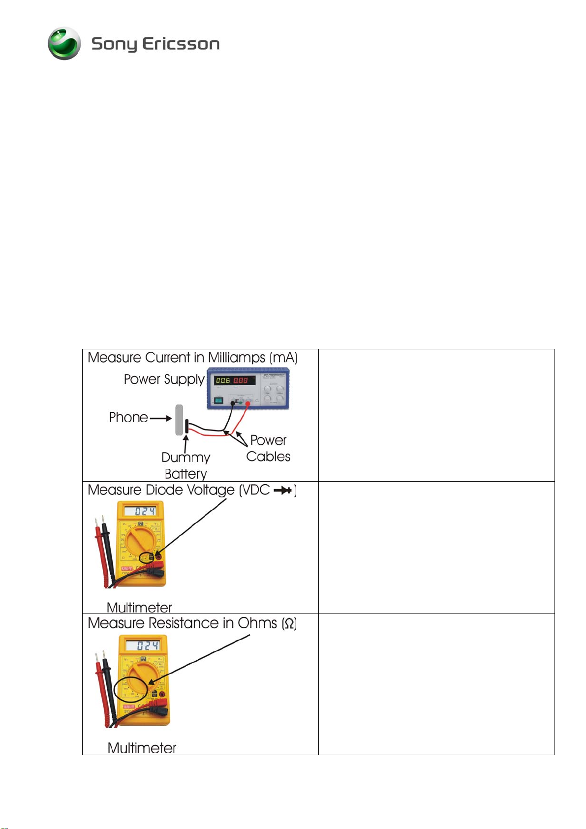
Voltage, current, and resistance information is provided for some symptoms to enable faster
repairs. Perform current measurements using a dummy battery and power supply with digital
current display. The phone should be fully assembled. Perform volta ge and re sistance measu rements with a multimeter. Purchasing this equipment and performing these measurements is
optional but recommended.
Perform current measurements using a
dummy battery and power supply with digital
current display. The phone should be fully
assembled.
Perform voltage measurements with a
multimeter.
Perform resistance measurements with a
multimeter.
State: Released Rev 2 2(7)
Company Internal
© Sony Ericsson Mobile Communi cat i ons AB
Page 3
Trouble Shooting Guide Repair Instruction Electrical/, Electrical
2 Repair Actions for Manual Test Failures
Failure Failure Symptom
2.1 Power
Current draw greater than 300 mAmps
On / Off
Current draw when powered off.
Using no current when On/Off key is pressed and will not start.
Hangs at gray display. Constant vibration. Will not power off.
Draws current when pushing On/Off key, returns to zero.
Will not power off.
Repair Action
• N2404 if getting hot
• N1002 inside module N1200
• N1200
• N1210
• N2404
• N1002 inside module N1200
• N1200
• N1210
• X4200 if damaged
• B2100
• N2202
• L2200
• N1200
• V2408
2.2 Software
/ USB
Flash
2.3 Charging
Other symptoms
Charging from power outlet
Charging from computer via USB
• X2200 if damaged
• X2400 if damaged
• N2402 if not charging via USB
• N2410 if pin 10 or 11 at X2400
are short circuit to GND
• N2404
• X2400 if damaged
• X2200 if damaged
• V2421 if short circuit
• V2200 if short circuit
• R2432 if more than 1 Ohm
• R2434 if more than 1 Ohm
• V2202
• X2400 if damaged
• N2402
State: Released Rev 2 3(7)
Company Internal
© Sony Ericsson Mobile Communi cat i ons AB
Page 4

Trouble Shooting Guide Repair Instruction Electrical/, Electrical
Failure Failure Symptom
2.4 Hands-Free
connection
Phone stuck in PHF mode when PHF is not
attached.
(PHF)
Repair Action
• V2420 if short circuit
• N2400
• V2405
Phone not recognizes PHF set.
2.5 SIM
2.6 Display
2.7 Display Illumination and Navigation Keys Illumination
2.8 Numeric Keyboard Illumination
2.9 Numeric Keyboard
2.10 Volume Up Key
2.11 Volume Down Key
2.12 Walkman Key
2.13 Navigation Keys
• X2400 if damaged
• X2420 if damaged
• X4200 if damaged
• Z4200
• Z4201
• Z4202
• Z4203
• X4200 if damaged
• N4200
• X2430 if damaged
• X2430 if damaged
• X2430 if damaged
• X2430 if damaged
• X2430 if damaged
• X4200 if damaged
2.14 Navigation Keys Illumination
2.15 Real Time clock
The clock has to be set after the battery has been detached.
Note very short time compare to other models.
The clock gain or lose time.
SERP calibrating is performed.
2.16 Polyphonic Top Speaker (Loudspeaker Top)
2.17 Polyphonic Bottom Speaker (Loudspeaker Bottom)
2.18 Hands-free (PHF) Aux Earphone
2.19 Earphone
2.20 Microphone
• X4200 if damaged
• C2217
• B2100
• N3102
• X2430 if damaged
• N3100
• X2400 if damaged
• L2403 if more than 1 Ohm
• L2404 if more than 1 Ohm
• L2411 if more than 1 Ohm
• N3101
• X4200 if damaged
• B3105
State: Released Rev 2 4(7)
Company Internal
© Sony Ericsson Mobile Communi cat i ons AB
Page 5

Trouble Shooting Guide Repair Instruction Electrical/, Electrical
Failure Failure Symptom
Repair Action
2.21 Hands-Free (PHF) Aux Microphone
2.22 Camera
2.23 Opto Sensor
2.24 Slide Sensor
2.25 Vibrator
2.26 Accelerometer
2.27 Memory Card
2.28 Bluetooth
• X2400 if damaged
• L2401 if more than 1 Ohm
• L2402 if more than 1 Ohm
• L2421 if more than 1 Ohm
• L2422 if more than 1 Ohm
• N3101
• X4300 if damaged
• N4310
• N4311
• X4200 if damaged
• N2203
• X4200 if damaged
• B4200
• N2490
• X2410 if damaged
• X1400 if damaged
• X1401 if damaged
• N1400
2.29 FM Radio
• X2400 if damaged
• N1400
State: Released Rev 2 5(7)
Company Internal
© Sony Ericsson Mobile Communi cat i ons AB
Page 6

Trouble Shooting Guide Repair Instruction Electrical/, Electrical
3 Repair Actions for Go/No Go Test Failures
Failure Failure Symptom
3.1 Fails any part of Go/No Go testing
3.2 Fails Go/No Go test, but passes calibration
3.3 Fails Go/No Go test after passing calibration
Repair Action
• Run the calibration routine
• Replace the antenna
• Check X1201 for damage and replace if
necessary
• Rerun the phone through Go/No Go testing
• Change X1200 and retest
4 Repair Actions for Calibration Failures
Failure Failure Symptom
4.1 Fails any part of the calibration routine
Repair Action
• Replace X1200 if damaged
• N1200 GSM – Approved Centers Only
• N1210 UMTS – Approved Centers Only
• N2205 UMTS
State: Released Rev 2 6(7)
Company Internal
© Sony Ericsson Mobile Communi cat i ons AB
Page 7

Trouble Shooting Guide Repair Instruction Electrical/, Electrical
4.2 Revision History
Rev. Date Changes / Comments
1 2008-09-26 First release
2 2009-03-06 N2404 added to On/Off problems
State: Released Rev 2
Company Internal
© Sony Ericsson Mobile Communi cat i ons AB
7(7)
 Loading...