

Page 1

Working Instruction, Electrical
Working Instruction, Electrical
Applicable for W595
CONTENTS
1 Read this first .........................................................................................3
2 Lead-free soldering ................................................................................ 4
3 Soldering issues..................................................................................... 6
3.1 Hot air gun temperature requirements .................................................. 6
3.2 Soldering tip temperature requirements ................................................ 6
3.3 Bottom heat requirements ..................................................................... 6
3.4 BGA rework specifications .................................................................... 6
4 Shield fence instruction......................................................................... 7
5 Preparations of Thor’s shield can lid ...................................................8
6 Replacement of components ................................................................9
6.1 Shield Cover........................................................................................ 10
6.2 B2100 Crystal 32,768 kHz................................................................... 11
6.3 B3105 Microphone .............................................................................. 11
6.4 B4200 Vibrator .................................................................................... 11
6.5 C2217 Capacitor 220 μF 4.0 V............................................................12
6.6 L2200 Inductor Wire wound 4.7 μH.....................................................12
6.7 L2401 - L2404 and L2411 Filter 0.0 Hz 0402...................................... 12
6.8 L2421 - L2422 Inductor 120nH 5% 0402 0.11A .................................. 13
6.9 N1002 IC Amplifier .............................................................................. 13
6.10 N1200 Thor2 Radio Module EDGE..................................................... 13
6.11 N1210 RF-Module Squid prebumped.................................................. 14
6.12 N1400 Module Bluetooth + FM STLC2592 ......................................... 14
6.13 N2202 IC Vreg 600mA ........................................................................ 14
6.14 N2203 IC Vreg PLP1010-4.................................................................. 15
6.15 N2205 DC/DC Converter..................................................................... 15
6.16 N2400 1-Bit Level Translator............................................................... 15
6.17 N2402 IC ESD Prot UDFN 6 2x2 mm ................................................. 16
6.18 N2404 IC IF ISP1508 ES3 (3.5*3.5*0.8) ............................................. 16
6.19 N2410 IC ESD Prot CS-5.................................................................... 16
6.20 N2490 ASIC Accelerometer ................................................................ 17
6.21 N3100 IC CS-9.................................................................................... 17
6.22 N3102 IC CS-9.................................................................................... 17
6.23 N3101 ASIC Tjatte3 CSP20................................................................ 18
6.24 N4200 Trans N-ch FET ....................................................................... 18
6.25 N4310 IC Vreg..................................................................................... 18
6.26 N4311 IC Vreg..................................................................................... 19
6.27 R2432 and R2434 Resistor 0 Ohm +/-50m 63mW K0603 .................. 19
6.28 V2200 Zener diode.............................................................................. 19
1215-7375 Rev 1
Company Internal
© Sony Ericsson Mobile Communi cat i ons AB
Page 2

Working Instruction, Electrical
6.29 V2202 Trans P-ch FET........................................................................ 20
6.30 V2405 MOSFET Complementary N P 20 V (DS)................................20
6.31 V2408 Schottky Barrier Diode 2PIN.................................................... 20
6.32 V2420 Zenner Diode 15V.................................................................... 21
6.33 V2421 Zenner Diode 15V.................................................................... 21
6.34 X1200 Conn Receptacle 0p Hirose RF connector .............................. 21
6.35 X1201 Antenna connector................................................................... 22
6.36 X1400 and X1401 Antenna connector ................................................ 22
6.37 X2200 Battery Connector.................................................................... 22
6.38 X2400 System Connector ................................................................... 23
6.39 X2410 MS Connector.......................................................................... 23
6.40 X2420 SIM Connector......................................................................... 23
6.41 X2430 Connector FPC 25p ................................................................. 24
6.42 X4200 Connector FPC 51p ................................................................. 24
6.43 X4300 Connector FPC 26p ................................................................. 24
6.44 Z4200 - Z4203 LC Filter ...................................................................... 25
7 Revision History ................................................................................... 26
1215-7375 Rev 1
Company Internal
2(26)
© Sony Ericsson Mobile Communi cat i ons AB
Page 3

Working Instruction, Electrical
1 Read this first
CAUTION
Keep all contact surfaces clean, no dirt or hand grease!
Before you start replacing any components, make sure you have read and fully understood
the contents of section 2 – 5.
Also make sure you have access to the mechanical Working Instruction and the equipment
listed on the first page of section 6.
Attention! All repair action with Hot air station or BGA repair station around and on the
opposite side of these components shall be performed with care, if the soldering joints
temperature on these components will reach 220 degrees than soldering of these
components will be damaged.
Protect the phone from ESD damages whenever it has been opened by using:
• ESD-wristband
• ESD-gloves
1215-7375 Rev 1
Company Internal
3(26)
© Sony Ericsson Mobile Communi cat i ons AB
Page 4
Working Instruction, Electrical
2 Lead-free soldering
KEEP ALL CONTACT SURFACES CLEAN OF DIRT AND HAND
GREASE
!
THIS PRODUCT IS MANUFACTURED WITH LEAD-FREE SOLDER
AND LEAD
-FREE COMPONENTS!
During electrical repair, it is critical to make sure that no
lead is introduced.
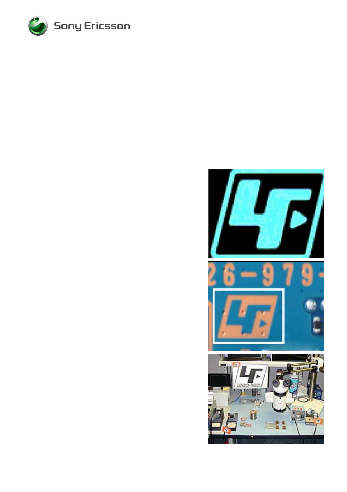
This symbol indicates that the product is lead- free.
All lead-free PBA’s will be marked with this symbol.
A lead-free work area must be set up completely separated
from work areas that are used to make lead repairs.
The lead-free work area must also be clearly labeled with
the lead free symbol as shown in the adjacent picture.
The items on this desk must remain lead-free.
They must be adequately labeled to make their lead-free
status clearly and easily recognized.
1215-7375 Rev 1
Company Internal
© Sony Ericsson Mobile Communi cat i ons AB
4(26)
Page 5
Working Instruction, Electrical
Lead-free soldering continued
LFS (lead-free solder paste) characteristics:
• High melting point (typically 220°C)
• Low wettability
• High surface tension
• Difficult to spread
• Recommended tip temperature = 360°C
WHEN SERVICING PBA’S THAT HAVE BEEN MANUFACTURED
LFS (LEAD-FREE SOLDER PASTE), LFS MUST BE USED.
WITH
I
F NOT, THERE IS A HIGH RISK FOR UNRELIABLE SOLDERING
JOINTS.
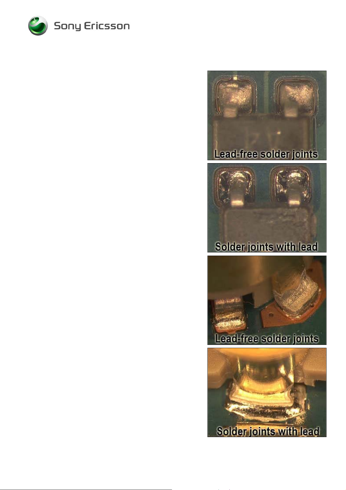
Lead-free solder joints are more difficult to inspect because
they do not have shiny surfaces like leaded solder joints.
Also, lead-free solder does not flow as well as leaded
solder, so some of the solder pad areas may remain
exposed.
1215-7375 Rev 1
Company Internal
5(26)
© Sony Ericsson Mobile Communi cat i ons AB
Page 6

Working Instruction, Electrical
3 Soldering issues
3.1 Hot air gun temperature requirements
The air temperature shall not exceed 360°C. The temperature shall be measured 5 mm from the
nozzle outlet.
If it’s not possible to remove and/ or solder with 360°C a BGA Rework Station or another repair
process shall be considered to ensure high process control.
Too high temperature can cause damage and cracks due to thermal stress on sensitive components,
e.g. ceramic components like capacitors.
3.2 Soldering tip temperature requirements
The soldering tip temperature shall be minimum 310°C and maximum 360°C.
Too high temperature can cause damage and cracks due to thermal stress on sensitive components,
e.g. ceramic components like capacitors.
3.3 Bottom heat requirements
In the chapter “Replacement of components” there are components which require to us a bottom
heater during repair to pre-heat the board and to level out the ∆T on the PBA. It will also minimize
thermal stress.
The temperature on the PBA surface shall not exceed 150°C to minimize inter-metallic growth and
thermal stress on PWB.
3.4 BGA rework specifications
Follow the Technical Requirement, 1207-2949, for components that require use of BGA Rework
Station.
1215-7375 Rev 1
Company Internal
6(26)
© Sony Ericsson Mobile Communi cat i ons AB
Page 7
Working Instruction, Electrical
4 Shield fence instruction
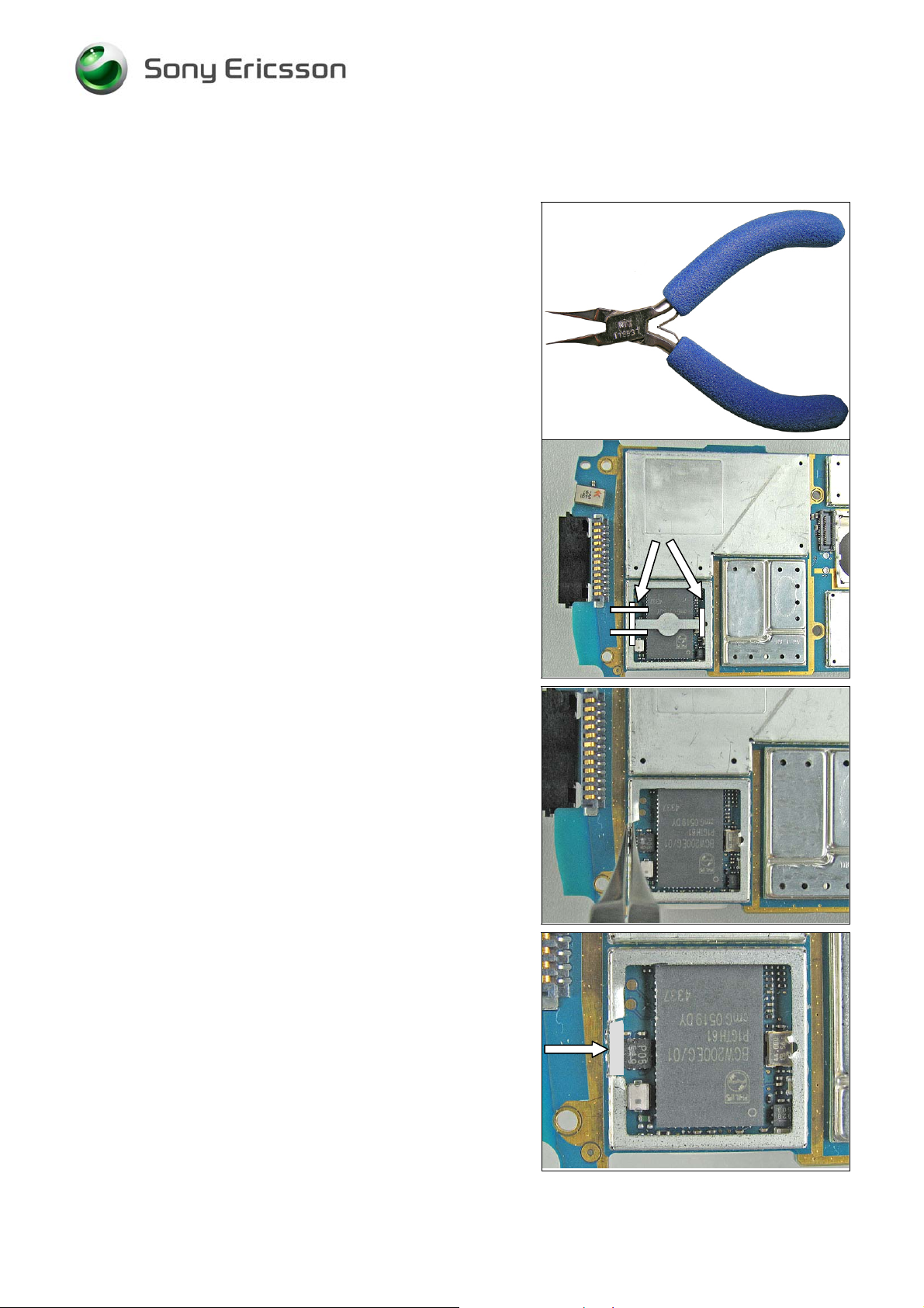
This instruction shows how to cut and bend the shield can
fence to be able to replace components under the fence.
Use a sharp-edged pliers to cut the fence.
Use Shield fence pliers NTZ 112 537 to bend the fence.
MAKE SURE THAT CUTTING PLIERS IS SHARP-EDGED TO
PREVENT DAMAGING THE SHIELD CAN FENCE
Remove the shield can lid, use a dentist hook.
Remove the pick up area according to the white lines with
cutting pliers. (1)
This pick up area is only used when machine mounting
and there is no need to put it back again.
Cut the shield can fence according to the white lines with
cutting pliers. (2)
.
1
1
1
2
2
2
Bend carefully the shield fence with a shield fence plier.
Replace the components.
Replace the components.
Bend carefully back the shield fence.
Put back a new shield can lid.
Press on all sides of the lid until you hear a “click” sound.
1215-7375 Rev 1
Company Internal
© Sony Ericsson Mobile Communi cat i ons AB
7(26)
Page 8
Working Instruction, Electrical
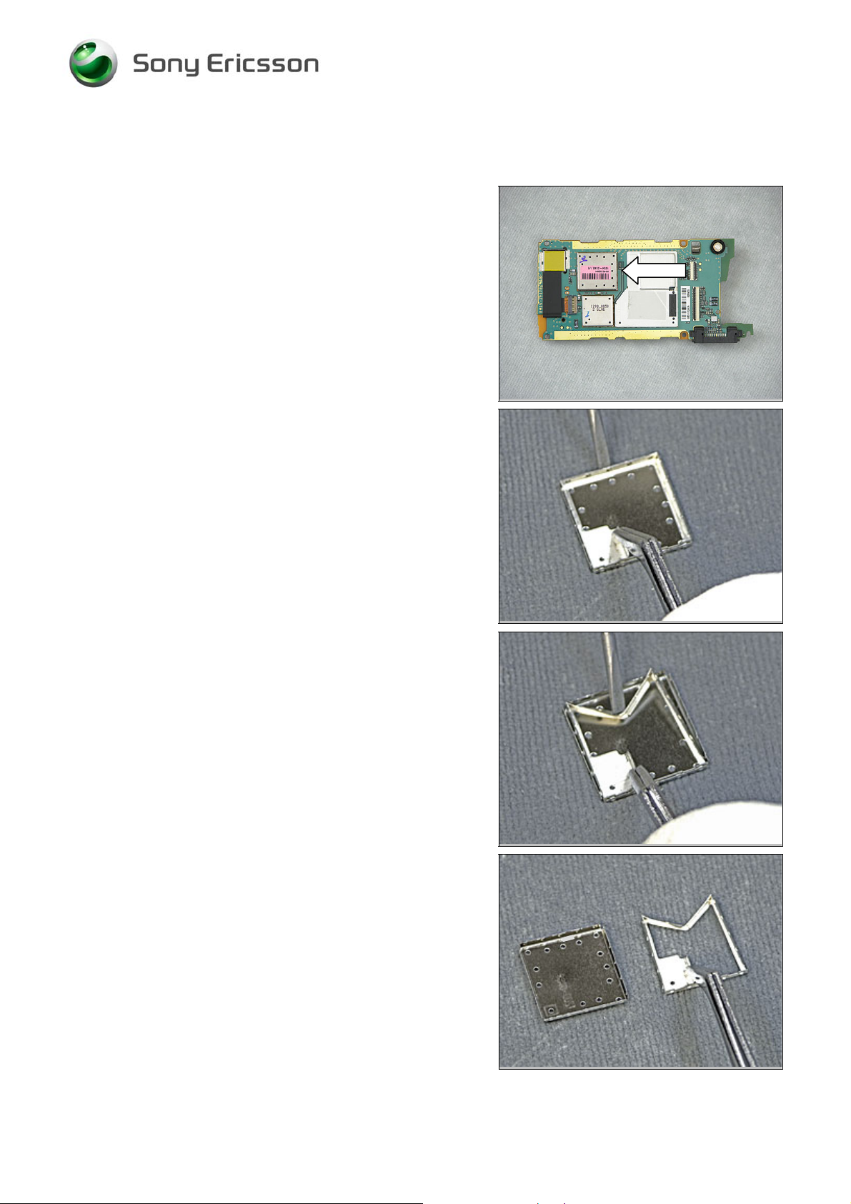
5 Preparations of Thor’s shield can lid
The shield can lid for Thor will be delivered together with
a fence. The fence has to be removed from the lid before
the lid can be used.
Use a screw driver and a par of tweezers.
Place the screw driver between the lid and the fence.
Press the shield can fence to the middle.
Use the tweezers to move the fence from the lid.
The shield can lid is now ready to use.
1215-7375 Rev 1
Company Internal
© Sony Ericsson Mobile Communi cat i ons AB
8(26)
Page 9

Working Instruction, Electrical
6 Replacement of components
EQUIPMENT
• Dentist hook
• ESD-gloves (cotton gloves)
• ESD-wristband
• Shield fence pliers NTZ 112 537
• Soldering iron
• Hot air soldering equipment
• BGA replacement equipment
• Pair of tweezers
• Soldering cleaning wiper (tin wick)
• Solder paste lead-free (SN 96% AG 3.5% Cu 0.5 %)
• Flux, RMA no-clean flux
• Cutting pliers
MECHANICAL INSTRUCTIONS
For all the following part replacements, disassemble and assemble the phone as described in
mechanical Working Instruction.
1215-7375 Rev 1
Company Internal
9(26)
© Sony Ericsson Mobile Communi cat i ons AB
Page 10

Working Instruction, Electrical
6.1 Shield Cover
REMOVAL
Use a dentist hook or a pair of tweezers to remove the
Shield Cover.
INSTALLATION
Replace a new Shield Cover after repair.
Press down the Shield Cover to snap all hooks onto the
shielding frame.
1215-7375 Rev 1
Company Internal
10(26)
© Sony Ericsson Mobile Communi cat i ons AB
Page 11

Working Instruction, Electrical
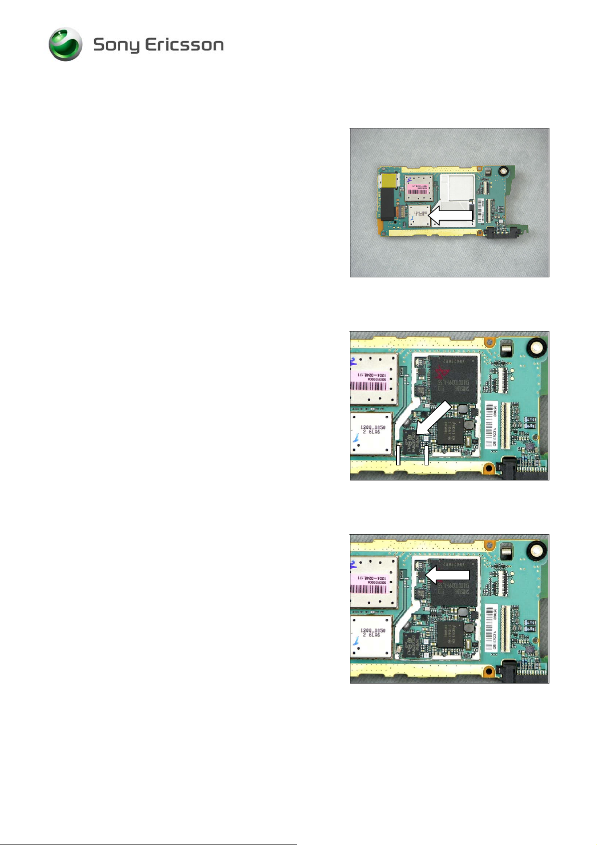
6.2 B2100 Crystal 32,768 kHz
Replace the Crystal with hot air soldering equipment.
6.3 B3105 Microphone
Remove the Microphone Gasket.
Replace the Microphone with hot air soldering equipment.
Protect the new Microphone with heat resisting tape.
Mount the Microphone
Gasket.
6.4 B4200 Vibrator
Protect the SIM connector with heat resisting tape.
Replace the Vibrator with a soldering iron or hot air
soldering equipment.
1215-7375 Rev 1
Company Internal
11(26)
© Sony Ericsson Mobile Communi cat i ons AB
Page 12

Working Instruction, Electrical
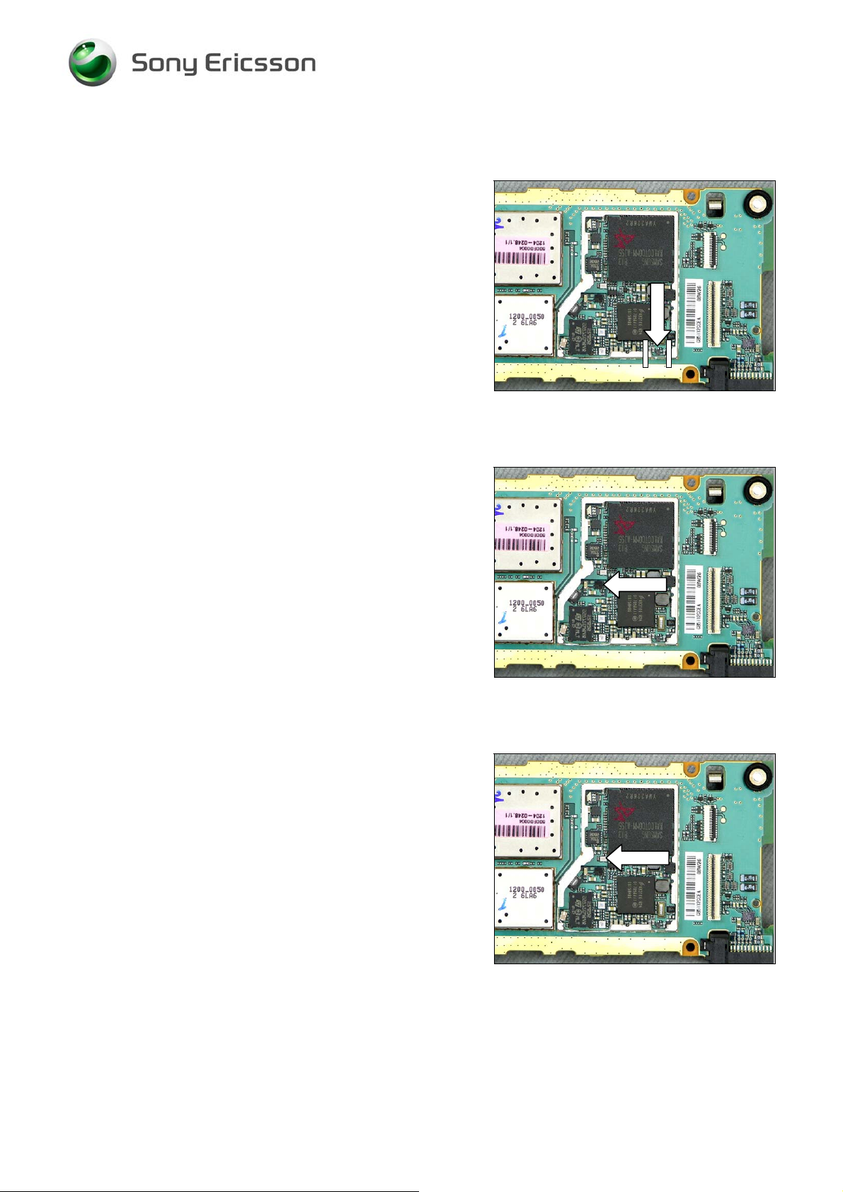
6.5 C2217 Capacitor 220 μF 4.0 V
Protect the Camera FPC and the connector with heat
resisting tape.
Replace the Capacitor with a soldering iron or hot air
soldering equipment.
6.6 L2200 Inductor Wire wound 4.7 μH
Protect D2000 and N2000 with heat resisting tape.
Replace the Inductor with hot air soldering equipment.
6.7 L2401 - L2404 and L2411 Filter 0.0 Hz 0402
Protect the System connector with heat resisting tape.
Replace the Filter with a soldering iron or hot air soldering
equipment.
1215-7375 Rev 1
Company Internal
12(26)
© Sony Ericsson Mobile Communi cat i ons AB
Page 13

Working Instruction, Electrical
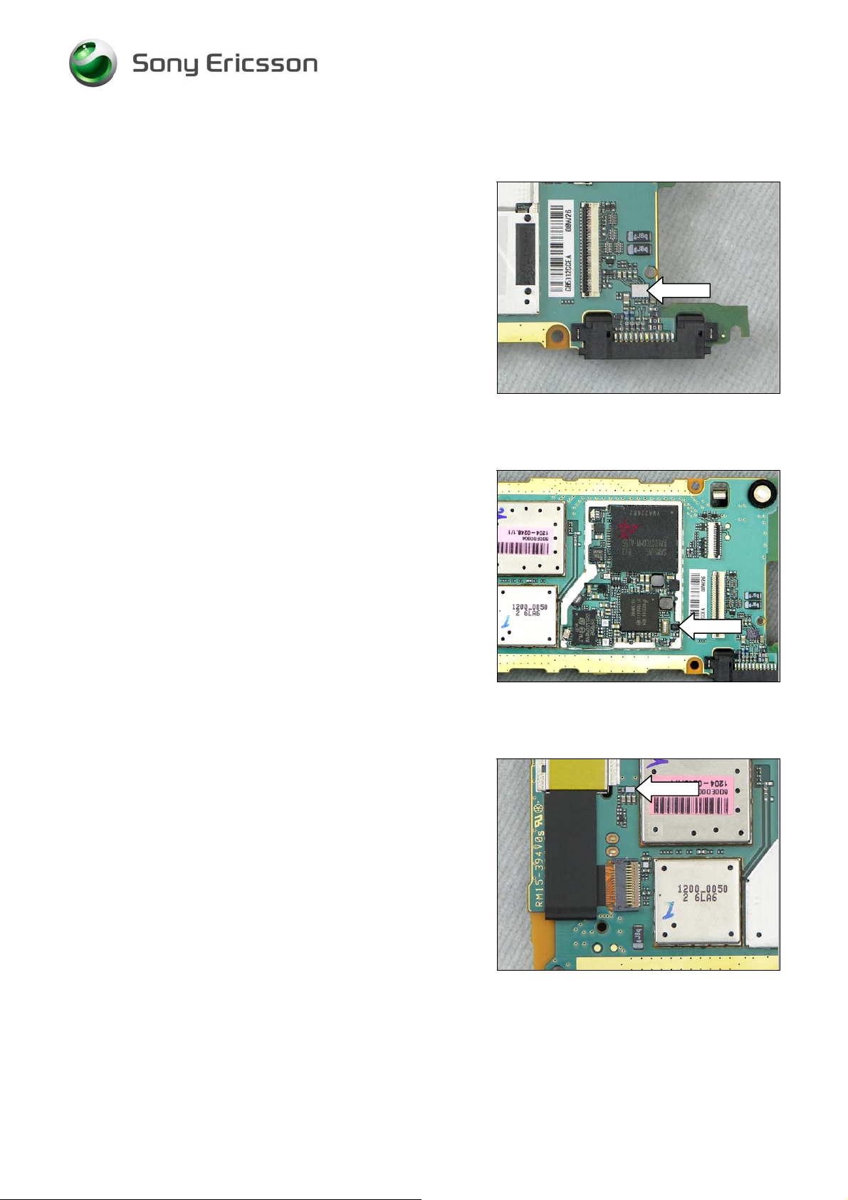
6.8 L2421 - L2422 Inductor 120nH 5% 0402 0.11A
Protect the System connector with heat resisting tape.
Replace the Inductor with a soldering iron or hot air
soldering equipment.
6.9 N1002 IC Amplifier
Remove the shield can lid with a dentist hook.
Replace the IC Amplifier with hot air soldering or BGA
equipment.
Prepare a new shield can lid (see chapter 5 for further
instructions).
Mount the new shield can lid with your fingers and press
the shield can lid to attach it.
A CLICKING SOUND WILL CONFIRM A SECURE FIT!
6.10 N1200 Thor2 Radio Module EDGE
Protect the Camera FPC and the connector with heat
resisting tape.
Replace the Radio Module with BGA equipment.
1215-7375 Rev 1
Company Internal
13(26)
© Sony Ericsson Mobile Communi cat i ons AB
Page 14
Working Instruction, Electrical
6.11 N1210 RF-Module Squid prebumped
Protect the Camera FPC and the connector with heat
resisting tape.
Replace the Radio Module with BGA equipment.
6.12 N1400 Module Bluetooth + FM STLC2592
Cut and bend the shield can fence to be able to replace
components under the fence according ‘Shield fence
instruction’.
Replace the Bluetooth Module with hot air soldering
equipment or BGA equipment.
6.13 N2202 IC Vreg 600mA
Replace the IC with hot air soldering equipment.
1215-7375 Rev 1
Company Internal
14(26)
© Sony Ericsson Mobile Communi cat i ons AB
Page 15
Working Instruction, Electrical
6.14 N2203 IC Vreg PLP1010-4
Cut and bend the shield can fence to be able to replace
components under the fence according ‘Shield fence
instruction’.
Replace the IC with hot air soldering equipment.
6.15 N2205 DC/DC Converter
Cut and remove the shield can roof to be able to replace
components under the roof according ‘Shield fence
instruction’.
Replace the Converter with hot air soldering equipment.
6.16 N2400 1-Bit Level Translator
Cut and remove the shield can roof to be able to replace
components under the roof according ‘Shield fence
instruction’.
Replace the Translator with hot air soldering equipment.
1215-7375 Rev 1
Company Internal
15(26)
© Sony Ericsson Mobile Communi cat i ons AB
Page 16

Working Instruction, Electrical
6.17 N2402 IC ESD Prot UDFN 6 2x2 mm
Cut and bend the shield can fence to be able to replace
components under the fence according ‘Shield fence
instruction’.
Replace the IC with a soldering iron or hot air soldering
equipment.
6.18 N2404 IC IF ISP1508 ES3 (3.5*3.5*0.8)
Replace the IC with hot air soldering equipment.
6.19 N2410 IC ESD Prot CS-5
Cut and bend the shield can fence to be able to replace
components under the fence according ‘Shield fence
instruction’.
Replace the IC with hot air soldering equipment.
1215-7375 Rev 1
Company Internal
16(26)
© Sony Ericsson Mobile Communi cat i ons AB
Page 17

Working Instruction, Electrical
6.20 N2490 ASIC Accelerometer
Replace the Accelerometer with hot air soldering
equipment.
6.21 N3100 IC CS-9
Replace the IC with hot air soldering equipment.
6.22 N3102 IC CS-9
Cut and bend the shield can fence to be able to replace
components under the fence according ‘Shield fence
instruction’.
Replace the IC with hot air soldering equipment.
1215-7375 Rev 1
Company Internal
17(26)
© Sony Ericsson Mobile Communi cat i ons AB
Page 18
Working Instruction, Electrical
6.23 N3101 ASIC Tjatte3 CSP20
Protect the System connector and the ZIF Connector with
heat resisting tape.
Replace the ASIC with hot air soldering equipment.
6.24 N4200 Trans N-ch FET
Replace the Transistor with hot air soldering equipment.
6.25 N4310 IC Vreg
Replace the IC with hot air soldering equipment.
1215-7375 Rev 1
Company Internal
18(26)
© Sony Ericsson Mobile Communi cat i ons AB
Page 19

Working Instruction, Electrical
6.26 N4311 IC Vreg
Protect the Camera FPC and the connector with heat
resisting tape.
Replace the IC with hot air soldering equipment.
6.27 R2432 and R2434 Resistor 0 Ohm +/-50m 63mW K0603
Protect the System connector with heat resisting tape.
Replace the Resistor with a soldering iron or hot air
soldering equipment.
6.28 V2200 Zener diode
Replace the Diode with a soldering iron or hot air
soldering equipment.
1215-7375 Rev 1
Company Internal
19(26)
© Sony Ericsson Mobile Communi cat i ons AB
Page 20

Working Instruction, Electrical
6.29 V2202 Trans P-ch FET
Replace the Transistor with hot air soldering equipment.
6.30 V2405 MOSFET Complementary N P 20 V (DS)
Replace the MOSFET transistor with a soldering iron or
hot air soldering equipment.
6.31 V2408 Schottky Barrier Diode 2PIN
Protect the ZIF Connector with heat resisting tape.
Replace the Diode with a soldering iron or hot air
soldering equipment.
1215-7375 Rev 1
Company Internal
20(26)
© Sony Ericsson Mobile Communi cat i ons AB
Page 21

Working Instruction, Electrical
6.32 V2420 Zenner Diode 15V
Cut and bend the shield can fence to be able to replace
components under the fence according ‘Shield fence
instruction’.
Replace the Diode with a soldering iron or hot air
soldering equipment.
6.33 V2421 Zenner Diode 15V
Protect the System connector with heat resisting tape.
Replace the Diode with a soldering iron or hot air
soldering equipment.
6.34 X1200 Conn Receptacle 0p Hirose RF connector
Remove the Connector with hot air soldering equipment.
Replace a new Connector with a soldering iron.
NOTE:
Make sure flux does not get on the component body.
Use as little flux as possible to place the new part.
1215-7375 Rev 1
Company Internal
21(26)
© Sony Ericsson Mobile Communi cat i ons AB
Page 22

Working Instruction, Electrical
6.35 X1201 Antenna connector
Replace the Connector with a soldering iron.
6.36 X1400 and X1401 Antenna connector
Replace the Connector with a soldering iron.
6.37 X2200 Battery Connector
Remove the Battery Connector with hot air soldering
equipment.
Replace a new Connector with a soldering iron or BGA
equipment.
1215-7375 Rev 1
Company Internal
22(26)
© Sony Ericsson Mobile Communi cat i ons AB
Page 23

Working Instruction, Electrical
6.38 X2400 System Connector
Remove the Connector with a soldering iron or hot air
soldering equipment.
Mount the new Connector with a soldering iron.
6.39 X2410 MS Connector
Protect the SIM connector with heat resisting tape.
Remove the Connector with hot air soldering equipment.
Use BGA soldering equipment to replace the Connector.
6.40 X2420 SIM Connector
Remove the SIM Connector with hot air soldering
equipment.
Replace a new Connector with a soldering iron or BGA
equipment.
1215-7375 Rev 1
Company Internal
23(26)
© Sony Ericsson Mobile Communi cat i ons AB
Page 24

Working Instruction, Electrical
6.41 X2430 Connector FPC 25p
Protect the Connector FPC 51p with heat resisting tape.
Remove the Connector with hot air soldering equipment.
Replace a new Connector with a soldering iron. Bottom
heat is required.
6.42 X4200 Connector FPC 51p
Protect the Connector FPC 25p and the System
connector with heat resisting tape.
Remove the Connector with hot air soldering equipment.
Replace a new Connector with a soldering iron. Bottom
heat is required.
6.43 X4300 Connector FPC 26p
Disassembly the Camera.
Remove the Connector with hot air soldering equipment.
Replace a new Connector with a soldering iron. Bottom
heat is required.
Reassembly the Camera.
1215-7375 Rev 1
Company Internal
24(26)
© Sony Ericsson Mobile Communi cat i ons AB
Page 25

Working Instruction, Electrical
6.44 Z4200 - Z4203 LC Filter
Protect the ZIF Connector with heat resisting tape.
Replace the Filter with a soldering iron or hot air soldering
equipment.
1215-7375 Rev 1
Company Internal
25(26)
© Sony Ericsson Mobile Communi cat i ons AB
Page 26

Working Instruction, Electrical
7 Revision History
Rev. Date Changes / Comments
1 2008-09-26 First release
1215-7375 Rev 1
Company Internal
26(26)
© Sony Ericsson Mobile Communi cat i ons AB
 Loading...