

Page 1
Equipment List, Electrical
Equipment List, Electrical
Applicable for W380, Z555
Contents
General................................................................................................................................................................ 2
1
2 Column Definitions............................................................................................................................................. 2
Description Columns ............................................................................................................................................ 2
Process Columns ................................................................................................................................................. 2
3 Repair Equipment............................................................................................................................................... 3
3.1 Repair Equipment orderable from Sony Ericsson...................................................................................3
3.2 Repair Equipment that should be obtained from local Suppliers............................................................ 7
3.3 Lead-free Solder Equipment................................................................................................................. 18
4 Revision History............................................................................................................................................... 21
1208-3984 1
Company Internal
© Sony Ericsson Mobile Communications AB
Page 2
Equipment List, Electrical
1 General
This document describes the equipment needed, in addition to the equipment listed in the Mechanical Equipment List, to upgrade
the applicable product(s)’s software, functional test and to repair the product(s) at an Electrical Repair Level. The first section is
equipment that can be purchased from a Sony Ericsson Parts and Tools warehouse. The second section is equipment that must be
purchased from other vendors.
2 Column Definitions
Description Columns
• Description = The name of the equipment.
• Part Number = The Sony Ericsson part number to use when ordering from a Sony Ericsson Parts and Tools warehouse.
• Comments = Additional information that helps to specify or clarify the equipment.
• Picture
Process Columns
These columns show which processes use the equipment. An “X” in a column indicates that the equipment must be used, and a “Z”
in a column indicates that the use of that equipment is optional.
Customization: Equipment necessary to perform a Customization/Activation.
Go/No Go test: Equipment necessary for Go/No Go testing.
Calibration with SERP: Equipment necessary to perform a calibration with SERP.
NOTE: Calibration can only be done by authorized repair centers.
Repair: Equipment necessary for replacing soldered components.
1208-3984 1
Company Internal
© Sony Ericsson Mobile Communications AB
2(21)
Page 3
Equipment List, Electrical
3 Repair Equipment
Some of the required equipment will be orderable from Sony Ericsson and some equipment has to be sourced locally. The following
sections are structured based on whether equipment is obtained from Sony Ericsson or from a local supplier.
3.1 Repair Equipment orderable from Sony Ericsson
Go/No Go Test
Description Part Number Comments Picture
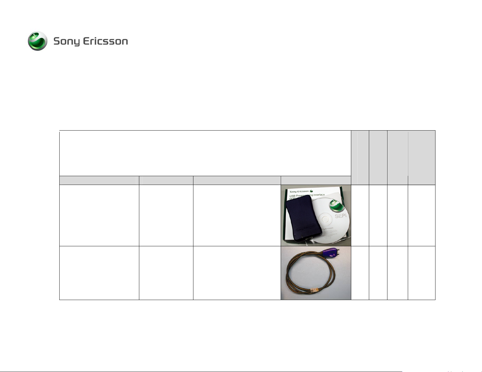
Sony Ericsson
Programming Interface
(SEPI)
LTN 214 1484 The Sony Ericsson
Programming Interface
(SEPI) is used in conjunction
with the SEPI interface
cable, the USB computer
cable and battery charger to
perform calibration on this
product.
Customization
X
SERP
Calibration in
Repair
Sony Ericsson
Programming Interface
(SEPI) cable
1208-3984 1
Company Internal
KRY 101 1119/1 A battery charger needs to
© Sony Ericsson Mobile Communications AB
be connected to this cable
during calibration.
X
3(21)
Page 4
Equipment List, Electrical
Go/No Go Test
Customization
SERP
Calibration in
Repair
Description Part Number Comments Picture
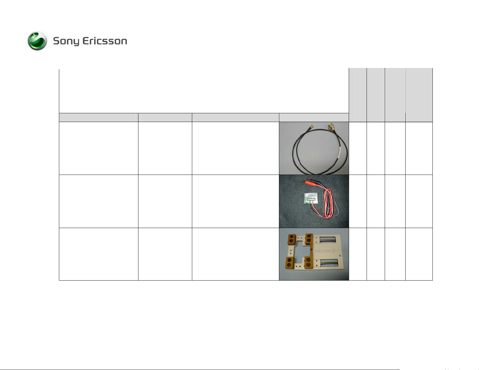
RF Cable RPM 119 855
X X
Dummy Battery
Rework Fixture for PCB LTD 260 273 Used to hold the PCB during
1208-3984 1
Company Internal
1200-4522
© Sony Ericsson Mobile Communications AB
If using the Dummy Battery
to power the handset during
the GNG Test or Calibration
routine you must use a high
quality DC source.
repair.
Z Z Z
X
4(21)
Page 5
Equipment List, Electrical
Go/No Go Test
Customization
SERP
Calibration in
Repair
Description Part Number Comments Picture
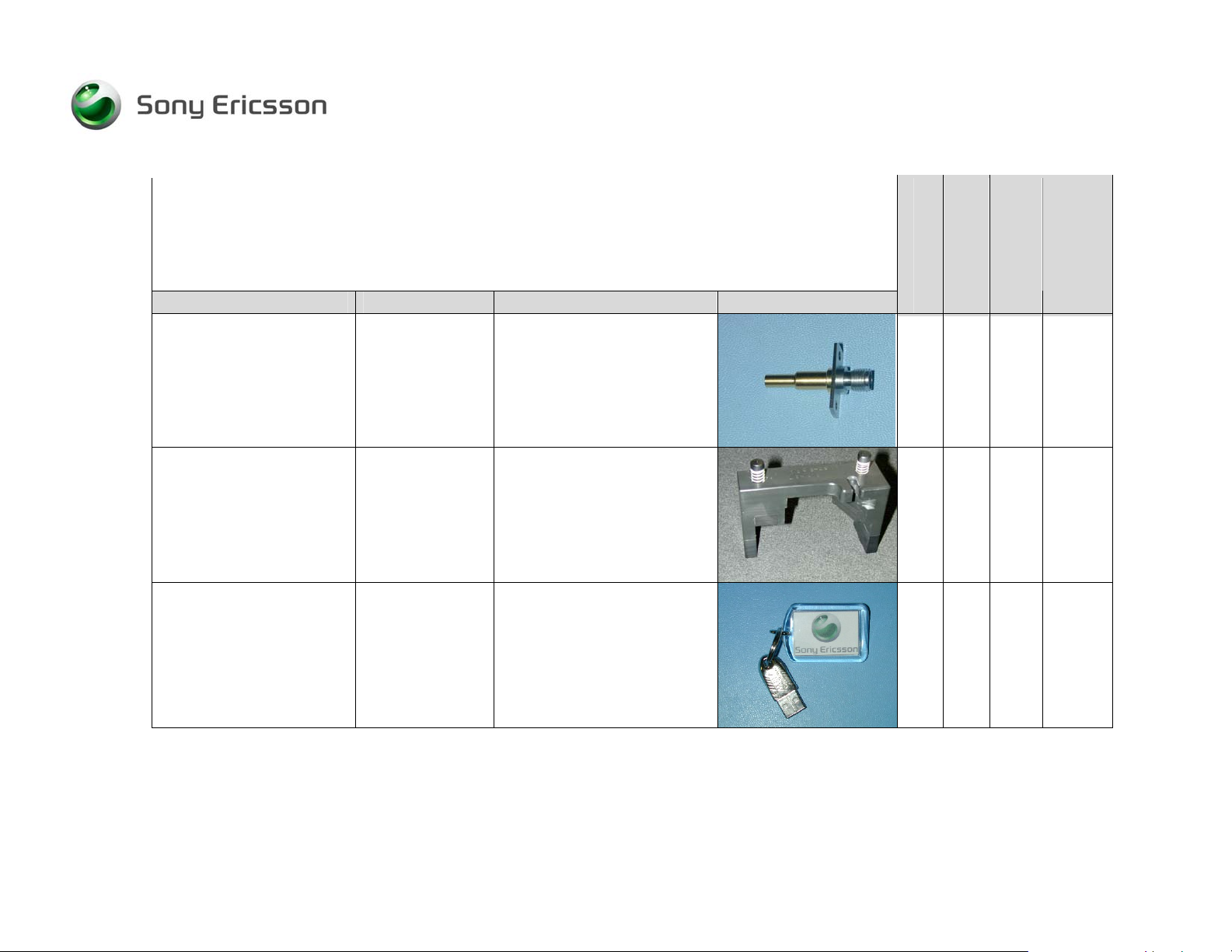
RF Probe
RPM 119 0201 Used together with the RF
Holder and RF Cable.
Z X
RF Holder
USB Activation Dongle NTZ 112 1071 Used for Activation in EMMA
1208-3984 1
Company Internal
1203-2916 Used together with RF probe
and RF cable.
Z X
III
X
5(21)
© Sony Ericsson Mobile Communications AB
Page 6
Equipment List, Electrical
Go/No Go Test
Customization
SERP
Calibration in
Repair
Description Part Number Comments Picture
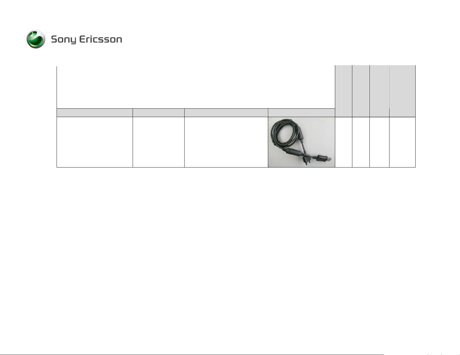
DCU-60/USB Cable KRY 101 1413 This cable is needed for
loading ITP software and
customization/activation.
X
1208-3984 1
Company Internal
6(21)
© Sony Ericsson Mobile Communications AB
Page 7
Equipment List, Electrical
3.2 Repair Equipment that should be obtained from local Suppliers
Description Comments
RF Shield Package
Rohde&Schwarz RF Shield
Package
• CMU-Z10 – Antenna
Coupler
(Partnr: 1150.0801.10)
• CMU-Z11 – RF Shield Cover
(Partnr. 1150.1008.02)
Using an RF shield package is one of the options for testing
the applicable product(s). Testing of the applicable
product(s) can also be performed by using the combination
of an RF Probe and an RF cable.
Spare parts for mobile phone fixation for R&S CMU-Z10 are
available for purchase from Rohde&Schwarz:
• Grid Positioning Plate – 1158.9789.00
• L-shaped bracket – 1158.9808.00
• Stabilizing pieces – 1158.9820.00
NOTE: The Rohde & Schwarz package will require the
use of a precision N-type male to SMA female RF
adapter to mate with the SEMC RF cable.
NOTE: If you are using a different RF Shield Package
than Rohde & Schwartz, special attenuation factors for
Go/No-Go test are required.
Customization
Go/No Go Test
Z
Calibration in
SERP
Repair
1208-3984 1
Company Internal
7(21)
© Sony Ericsson Mobile Communications AB
Page 8

Equipment List, Electrical
Customization
Go/No Go Test
Calibration in
SERP
Description Comments
RF adapter for RF shield box
• The adapter for a Rohde &
Schwarz Shield box must be a
precision N-type male to SMA
female adapter.
Battery Charger
(Standard SEMC charger
applicable for W380, Z555 )
USB Computer Cable Type A to Type B USB cable.
This adapter is used to connect the RF shield box to the RF
cable and is only required if a shield package is going to be
used for testing.
Recommended source:
• Pasternack Enterprises – (949) 261-1920 or
www.pasternack.com
Part number: PE9430
The battery charger needs to be connected to the Sony
Ericsson Programming Interface Cable during calibration.
Also used for Charger Test.
This is part of the hardware needed for performing
calibration. This cable connects the computer to the SEPI.
Z
X
X
Repair
1208-3984 1
Company Internal
8(21)
© Sony Ericsson Mobile Communications AB
Page 9

Equipment List, Electrical
Customization
Go/No Go Test
Calibration in
SERP
Description Comments
Test and Calibration Instrument
(Chose one of the following.)
Anritsu MT 8801B
Required Components:
• MT8801B (Radio Com.
Analyser)
• MT8801B-02 (SG-local)
• MX880115A (GSM
Measurement Software)
Required Software:
• Main 4.02
• System 4.05
Anritsu MT 8801C
Required Components:
• MT8801C (Radio Com.
Analyser)
• MX880115A (GSM
Measurement Software)
Required Software:
• Main 4.02
• System 4.05
If it is preferred to use a test instrument for GNG that is not
specified, the test script must be written according to the
GO/NO GO Test Spec for the W380 or Z555 and approval
of the test script must be obtained from Sony Ericsson.
Note: This instrument does not support the calibration
routine for the Z555 or W380.
Note: It is strongly recommended that the instrument
vendor be contacted before ordering this setup to
ensure that the options stated are still valid or that no
part numbers have changed.
Note: It is strongly recommended that the instrument
vendor be contacted before ordering this setup to
ensure that the options stated are still valid or that no
part numbers have changed.
Note: This instrument does not support the calibration
routine for the Z555 or W380.
X
X
Repair
1208-3984 1
Company Internal
9(21)
© Sony Ericsson Mobile Communications AB
Page 10

Equipment List, Electrical
Customization
Go/No Go Test
Calibration in
SERP
Description Comments
Anritsu MT 8802A
Required Components:
• MT8802A (Radio Com.
Analyser)
• MX880215A (GSM
Measurement Software)
Required Software:
• Main 1.11
• System 2.07
Agilent 8960
Required Components:
• E5515C (8960 Series 10
Mainframe)
• Option E5515C-002 (2nd RF
source)
Required Software
• E1968A-101 GSM and
E1968A-103 EGPRS Test
Application
or
• E1968A-202
GSM/GPRS/EGPRS Test
Application
Note: It is strongly recommended that the instrument
vendor be contacted before ordering this setup to
ensure that the options stated are still valid or that no
part numbers have changed.
Note: This instrument does not support the calibration
routine for the Z555 or W380.
Some older versions of the 8960 Series 10 mainframes may
need to have a hardware upgrade in order to have EDGE
capabilities. See your local Agilent representative for details
E1968A-103 is not necessary for Go/No Go testing only
Calibration.
Note: It is strongly recommended that the instrument
vendor be contacted before ordering this setup to
ensure that the options stated are still valid or that no
part numbers have changed.
X
X X
Repair
1208-3984 1
Company Internal
10(21)
© Sony Ericsson Mobile Communications AB
Page 11

Equipment List, Electrical
Customization
Go/No Go Test
Calibration in
SERP
Description Comments
Willtek 4403/4405
Required Components:
• Option 4460 (GSM System)
• Option 4468 (EDGE
System)
• Option 4477 (OCXO)
• Firmware 4.24 or greater
• The 4403 instrument needs
to have option # M897163
installed.
Willtek 4202
Required Components:
• M101302 - 4202S
Mainframe
• M 248 418 - GSM 850
option
• Firmware 5.50 or greater
Note: It is strongly recommended that the instrument
vendor be contacted before ordering this setup to
ensure that the options stated are still valid or that no
part numbers have changed.
This instrument is only capable of running a stand alone
Go/No Go test. (SERP not required.)
Note: This instrument does not support the calibration
routine.
Note: It is strongly recommended that the instrument
vendor be contacted before ordering this setup to
ensure that the options stated are still valid or that no
part numbers have changed.
X X
X
Repair
1208-3984 1
Company Internal
11(21)
© Sony Ericsson Mobile Communications AB
Page 12

Equipment List, Electrical
Customization
Go/No Go Test
Calibration in
SERP
Description Comments
Rohde & Schwarz CMU200
Required Components
• CMU200 mainframe
(Base Unit)
• Options CMU-B11,
CMU-B21, CMU-B52,
CMU-B54
• Required SW package:
CMU-PK20
Power Supply
(w/digital readout)
NOTE!
If using the Power Supply in
conjunction with the Dummy
Battery to power the phone
during the GNG test or
Calibration routine a high quality
DC source that meets the
following requirements must be
used.
Note: It is strongly recommended that the instrument
vendor be contacted before ordering this setup to
ensure that the options stated are still valid or that no
part numbers have changed.
Device Requirements:
• Output Voltage: 0-5 volt minimum.
• Output Current: 0-2 amps minimum.
• Transient response time: < 100 µs
Some examples of Power Supplies that meet these
requirements are as follows:
• Agilent 66xx ser
• Agilent 663x series
X X
Z Z Z
Repair
1208-3984 1
Company Internal
12(21)
© Sony Ericsson Mobile Communications AB
Page 13

Equipment List, Electrical
Customization
Go/No Go Test
Calibration in
SERP
Description Comments
Small Convection (Hot Air) Device
Large Convection (Hot Air) Device Use this device for large parts, shield cans, and BGA-type
Nozzles for Large Convection (Hot
Air) Device
Temperature Probes
(Thermocouples)
Digital Multi-meter
Microscope
Device Requirements:
• The device should allow variable adjustment over a
temperature range.
• The device should be capable of reaching an upper
temperature of 426.7oC (800oF) or more.
The range of airflow the device is capable of generating
should fall under 20 litre/minute.
components.
• The device should allow variable temperature
adjustment and be capable of reaching an upper
temperature of 426.7oC (800oF) or more.
The range of airflow the device is capable of generating
should be above 20 litre/minute.
NOTE: Only necessary if you have a large convection
device.
Used to measure temperatures on the board when replacing
parts with the Large Convection Device or creating
temperature profiles.
Used for troubleshooting failures.
Minimum magnification required is 10x.
X
X
X
X
Z
X
Repair
1208-3984 1
Company Internal
13(21)
© Sony Ericsson Mobile Communications AB
Page 14

Equipment List, Electrical
Customization
Go/No Go Test
Calibration in
SERP
Description Comments
GPIB Card National Instruments or Keithley
NOTES:
GPIB Cable
Power cable – Red
NOTE: Only necessary if using
the Dummy Battery.
• Drivers are required and should be supplied with a
card.
A GPIB card is not required if testing is being performed
using the Willtek 420x instrument.
This cable is only required if a GPIB card is used.
Cable Requirements:
• Minimum cross sectional area of conductor = 1.2mm2
• Maximum length = 1.5 m
• One end of cable must have a male banana-type
connector to be able to interface with the Dummy
Battery.
The other end of the cable needs whatever connection is
necessary to connect to the power supply that you have.
Z X
Z X
Z Z Z
Repair
1208-3984 1
Company Internal
14(21)
© Sony Ericsson Mobile Communications AB
Page 15

Equipment List, Electrical
Customization
Go/No Go Test
Calibration in
SERP
Description Comments
Power cable – Black
NOTE: Only necessary if using
the Dummy Battery.
Component baking oven
Cable Requirements:
• Minimum cross sectional area of conductor = 1.2mm2
• Maximum length = 1.5 m
• One end of cable must have a male banana-type
connector to be able to interface with the Dummy
Battery.
The other end of the cable needs whatever connection is
necessary to connect to the power supply that you have.
Temperature requirements: 125°C +5°C/-0°C
Required for drying moisture sensitive components.
Below are links to several companies that sell convection
ovens.
http://www.cascadetek.com/forcedlist.php
http://www.wisoven.com/lab1.htm
http://www.shellab.com/products.html
http://www.terrauniversal.com/products/tempcontrol/ovens/i
mperiaivmechcon.php
http://www.labsynergy.com/products_laboratoryovens.asp?k
eyword=*laboratoryovens
Z Z Z
X
Repair
1208-3984 1
Company Internal
15(21)
© Sony Ericsson Mobile Communications AB
Page 16

Equipment List, Electrical
Customization
Go/No Go Test
Calibration in
SERP
Description Comments
FLUX Lead-free solder does not require a special flux. The “No
Clean” flux used with leaded products is acceptable.
Although some manufacturers are developing fluxes
specially made for use with lead-free solder (higher
evaporation temperatures, less smoke, etc.), these are not
required.
Low Static Heat Protection Tape This tape is required to protect adjacent components from
hot air.
Computer One of the following operating systems must be used:
• Windows 2000 with service pack 2 or higher
• Windows XP
Minimum Requirements:
• One unused PCI slot for GPIB card
• 2 USB Ports
The processor and RAM of the computer should at least
meet the the minimum requirements specified by the
operating system’s manufacturer.
Test SIM According to your Instrument supplier X
Printer Optional, but recommended Z
X
X
X Z X
Repair
1208-3984 1
Company Internal
16(21)
© Sony Ericsson Mobile Communications AB
Page 17

Equipment List, Electrical
Customization
Go/No Go Test
Calibration in
SERP
Description Comments
Metal Cutters Use these to trim shield can fences when they obstruct
access to parts.
Cutters should be small enough to cut fences without
damaging parts on the board.
Cutters should be sharp enough to cut fences without
twisting or pulling the fence.
Recommended cutters available at www.MSCDirect.com:
Knipex (left) - Mfr Part #: KN7803-5, MSC #: 32997462
Xuron (right) - Mfr Part #: 2175AS, MSC #: 88356431
Repair
1208-3984 1
Company Internal
X
17(21)
© Sony Ericsson Mobile Communications AB
Page 18

Equipment List, Electrical
3.3 Lead-free Solder Equipment
The items in this table, and any other soldering tools or material that make physical contact with the solder, must remain lead-free.
They must be adequately labelled to make their lead-free status clearly and easily recognized.
Test
Pos Description Comments Picture
Lead-free Solder
Note: The solder must be composed of
Tin, Silver, and Copper, and nothing else.
The exact composition ratio may vary, but
it must be Tin, Silver, and Copper only.
This composition may also be known as
SnAgCu or SAC.
Lead-free labels
(sheet of 24)
SEMC Part # SVF9301379
(These labels are available from the Sony
Ericsson Parts and Tools Warehouse.)
Manufacturers of LF Solder:
- Tamura (www.tamura-kaken.co.jp)
Part # TLF-206-93F
- Multicore (www.multicore.com)
Part # 96SC
- Senju (www.senju-
m.co.jp)
Part # M705
Required for labeling all soldering tools
and materials that contact the solder.
Repair
X
X
1208-3984 1
Company Internal
18(21)
© Sony Ericsson Mobile Communications AB
Page 19

Equipment List, Electrical
Test
Repair
Pos Description Comments Picture
Soldering Tips
X
Soldering Iron
If one work bench is divided to
accommodate both leaded and lead-free
solder, then each side of the bench should
have its own iron.
Wicking Tape
1208-3984 1
Company Internal
© Sony Ericsson Mobile Communications AB
• The device should allow variable
temperature adjustment and be
capable of reaching an upper
temperature of 426.7oC (800oF) or
more.
X
X
19(21)
Page 20

Equipment List, Electrical
Test
Repair
Pos Description Comments Picture
Tip Tinner
Z
Tip Cleaner (steel wool)
Z
1208-3984 1
Company Internal
20(21)
© Sony Ericsson Mobile Communications AB
Page 21

Equipment List, Electrical
4 Revision History
Rev. Date Changes / Comments
1 2008-02-29 Initial release
1208-3984 1
Company Internal
21(21)
© Sony Ericsson Mobile Communications AB
 Loading...