

Page 1

Test Instruction, Electrical
Test Instruction, Electrical
Applicable for W380, Z555
Contents
General...............................................................................................................2
1
2 Go/No-Go Test...................................................................................................2
2.1 Go/No-Go Test Preparations.................................................................2
2.2 Willtek 4202 GNG (Stand alone)...........................................................4
2.3 SERP GNG ...........................................................................................5
3 Calibration..........................................................................................................6
3.1 Flashing the Test Program (ITP) into the Mobile...................................6
3.2 Calibration Instructions..........................................................................7
3.3 Updating the Commercial Software into the Mobile after Calibration....7
4 Revision History................................................................................................7
1208-3977 2
© Sony Ericsson Mobile Communications AB
Page 2
Test Instruction, Electrical
1 General
This document describes the test procedures for the electrical repair package.
2 Go/No-Go Test
This test verifies that the radio parameters of a mobile fulfil the GSM specifications. A
mobile is considered good if all measurements pass. All results will be presented on
the screen and can be printed out if a printer is available.
There are two options available for performing the GNG test, SERP GNG or a Stand
alone GNG.
There are two methods of running a Stand alone GNG test. The first is to use a script
provided by Sony Ericsson for the Willtek 4202 which can be downloaded from
CSPN as described in Installation Instructions, Electrical. The second is to write a
script in accordance with the GO/NO GO Test Script Specification, Electrical which is
located on CSPN.
Repair Instructions-Electrical/ ”Phone Model” / GO/NO GO Test Spec
2.1 Go/No-Go Test Preparations
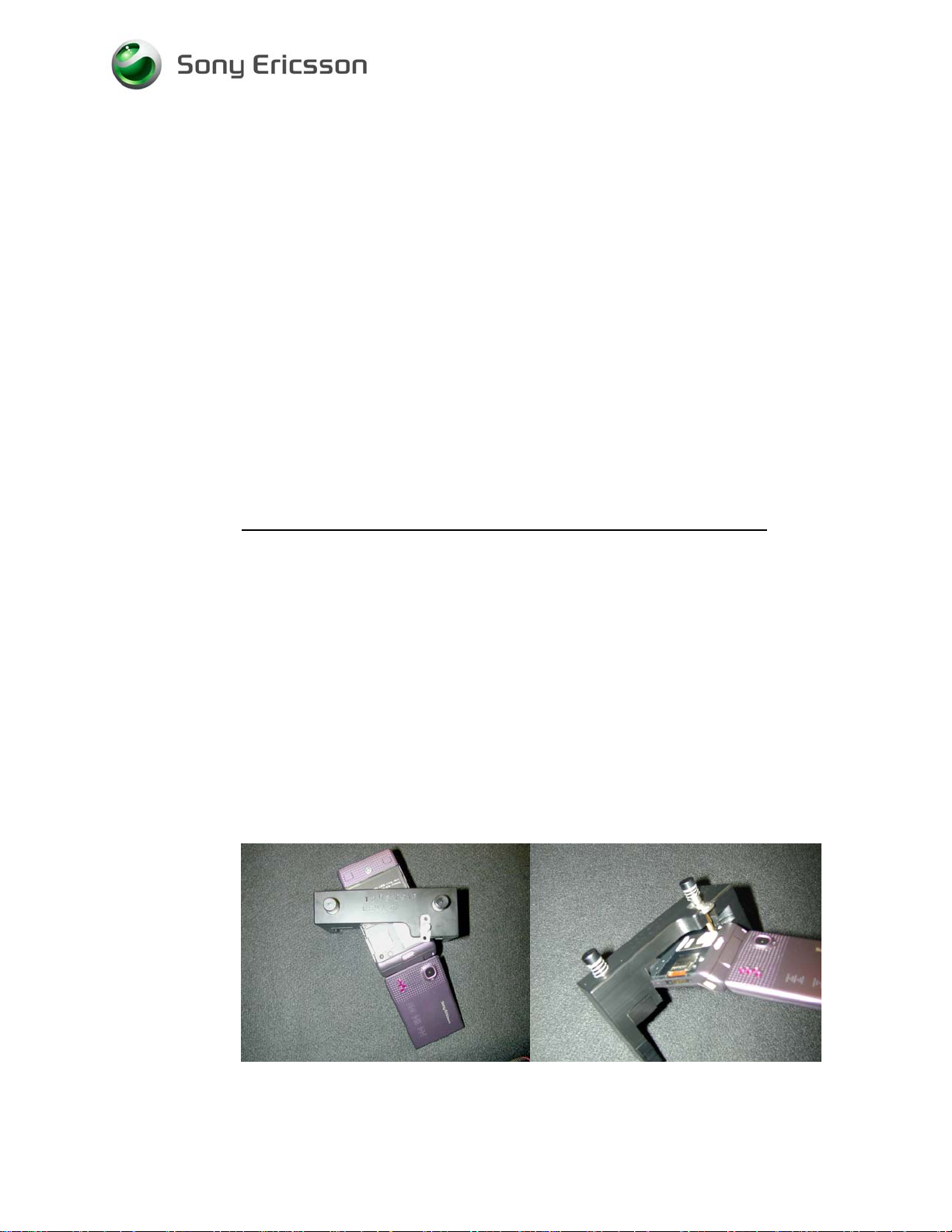
2.1.1 RF Test Fixture (Conducted Test Method)
1. Remove the back cover according to Working Instructions, Mechanical.
2. Insert a test SIM that is compatible with your Test Instrument and install a fully
charged standard battery to the mobile.
NOTE! A Dummy Battery may be used in place of a standard fully charged
battery if you use a power supply that meets the requirements that
are documented in the Electrical Equipment List.
3. Install the RF Probe in the RF Holder and attach to the mobile according to the
picture.
Picture 1 Picture 2
1208-3977 2
© Sony Ericsson Mobile Communications AB
2(7)
Page 3
Test Instruction, Electrical
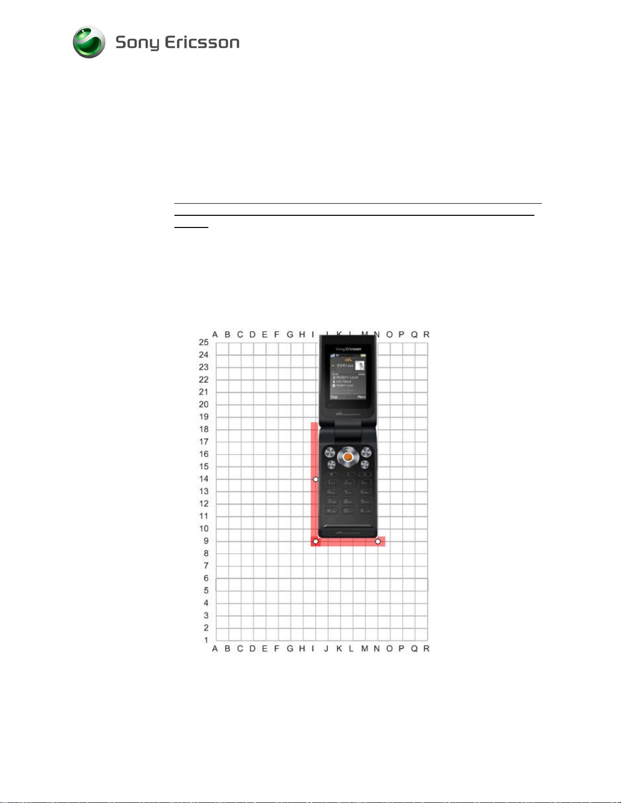
2.1.2 RF Coupler (Radiated Test Method)
1. Insert a test SIM and a fully charged standard battery. It is very important that a
standard fully charged battery is used; otherwise, there is a risk for wrong test
results.
2. Position the handset on the Grid Positioning plate in the coupler as shown with
the Reference point at I9. Additional information on the Grid Positioning plate and
other supported SEMC handsets that utilize the Grid Positioning plate, is
available in “SERPINFO.htm - R&S Grid plate for SERP” which is located on the
windows desktop after SERP is installed.
NOTE! THE GRID POSITION IS APPLICABLE FOR BOTH W380 AND Z555
Rohde & Schwarz Coupler with a Grid Positioning
plate Reference point I.9
1208-3977 2
© Sony Ericsson Mobile Communications AB
3(7)
Page 4

Test Instruction, Electrical
2.2 Willtek 4202 GNG (Stand alone)
1. For the W380a, start the instrument and run the test script:
• “W380a HL” if using the RF fixture.
• “W380a Grid” if using the Rhode & Schwarz coupler.
2. Follow the Instructions presented on the test instrument’s display.
1. For the W380i
• “W380i HL” if using the RF fixture.
• “W380i Grid” if using the Rhode & Schwarz coupler.
2. Follow the Instructions presented on the test instrument’s display.
1. For the Z555a
• “Z555a HL” if using the RF fixture.
• “Z555a Grid” if using the Rhode & Schwarz coupler.
2. Follow the Instructions presented on the test instrument’s display.
1. For the Z555i
• “Z555i HL” if using the RF fixture.
• “Z555i Grid” if using the Rhode & Schwarz coupler.
2. Follow the Instructions presented on the test instrument’s display.
, start the instrument and run the test script:
, start the instrument and run the test script:
, start the instrument and run the test script:
1208-3977 2
© Sony Ericsson Mobile Communications AB
4(7)
Page 5

Test Instruction, Electrical
2.3 SERP GNG
NOTE! FOR COMPLETE AND DETAILED USER INSTRUCTIONS, SEE THE
SERP USERS MANUAL LOCATED IN THE SERPINFO.HTM THAT
GETS PLACED ON THE DESKTOP AFTER SERP IS INSTALLED.
1. On a PC with SERP installed, start the SERP program by double clicking on the
“RepairManager.exe” icon on the desktop.
2. Click on “Settings” in the SERP Window and verify that the test instrument and
the GPIB address correspond.
3. Click on the “Station Setup” tab and verify that the “cable” (or the coupler)
settings are selected under the “RF Connection-GoNogo” Drop down window.
Click on “Apply” and then the “OK” button.
4. Enter (or scan) the IMEI number of the mobile to be tested into the “Enter IMEI”
box in the SERP Window and click on the “Load” button. The appropriate phone
model will be displayed.
5. In the SERP window, check the “Final GoNogo Test” box only. Click on the
“Start Test” button and follow the instructions. (Power on the phone when the
“Call Connection” dialog box appears.)
1208-3977 2
© Sony Ericsson Mobile Communications AB
5(7)
Page 6

Test Instruction, Electrical
3 Calibration
The Calibration Program in SERP should only be run as directed by the Electrical
Troubleshooting Guide or the Electrical Parts List.
NOTE! A TEST PROGRAM MUST BE LOADED IN THE HANDSET BEFORE
PERFORMING THE CALIBRATION ROUTINE. AFTER
CALIBRATION THE HANDSETS MUST BE RE-CUSTOMIZED WITH
SIGNALLING SW.
3.1 Flashing the Test Program (ITP) into the Mobile
Flash the “W380 or Z555 Test Program” software into the mobile by doing the
following:
1. Attach a fully charged battery to the mobile.
2. Open the EMMA III application and log in.
3. Ensure the mobile is powered off.
4. While holding the “C” button, connect the mobile to the USB Flash cable. (Once
the USB Icon appears in the EMMA III window, you may release the “C” button.)
5. Select the “W380 or Z555 ITP” protocol and follow the on screen instructions.
NOTE! UNDER MOST CIRCUMSTANCES, THE DISPLAY ON THE MOBILE
WILL BE BLANK WHEN THE TEST PROGRAM IS INSTALLED.
1208-3977 2
© Sony Ericsson Mobile Communications AB
6(7)
Page 7

Test Instruction, Electrical
3.2 Calibration Instructions
NOTE! FOR COMPLETE AND DETAILED USER INSTRUCTIONS, SEE THE
SERP USERS MANUAL LOCATED IN THE SERPINFO.HTM THAT
GETS PLACED ON THE DESKTOP AFTER SERP IS INSTALLED.
1. On a PC with SERP installed, start the SERP program by double clicking on the
“RepairManager.exe” icon on the desktop.
2. Click on the “Settings” button in the SERP Window to verify the test instrument,
GPIB address and the COM Port matches the SERP settings.
3. Click on the “Station Setup” tab and verify that “cable” is selected under the
“RF Connection-Calibration” Drop down window. Click on “Apply” and then
the “OK” button.
4. Enter (or scan) the IMEI number of the mobile to be calibrated into the “Enter
IMEI” box of the SERP Window and click on the “Load” button.
5. In the SERP window, check the “Calibration” box only.
6. Connect the mobile to the test instrument using the RF fixture (refer to section
2.1.1).
7. Connect the Sony Ericsson Programming Interface Cable to the mobile’s system
connector.
8. Click on the “Start Test” button in the SERP window to start the Calibration
routine (mobile will automatically turn on).
9. Monitor the progress of the calibration routine by viewing the information
presented in the “Test Manager” window.
10. If a calibration routine fails, troubleshoot according to the W380, Z555 Electrical
Troubleshooting Guide.
3.3 Updating the Commercial Software into the Mobile after
Calibration
To be able to use the handset after calibration requires going through the
Customization process which reloads the appropriate signalling code for the desired
operator. Refer to the W380, Z555 Build Swap Customization Instruction document
for further details on the Customization process.
4 Revision History
Rev. Date Changes / Comments
1 2008-02-29 Initial Release
2 2008-03-31 Updated Grid coupler position
1208-3977 2
© Sony Ericsson Mobile Communications AB
7(7)
 Loading...