

Page 1

Working Instruction, Mechanical
Working Instruction, Mechanical
Applicable for W380
CONTENTS
1
Introduction ............................................................................................................3
1.1 View of W380...............................................................................................3
1.2 Tools and Equipment ...................................................................................3
1.3 General Cautions......................................................................................... 4
1.4 Adhesives.....................................................................................................4
1.5 Using Hand and ESD Protection..................................................................4
1.6 Protection of Displays, Lenses, and Windows .............................................5
1.7 Acceptable Pry Tools...................................................................................5
2 Disassembly........................................................................................................... 6
2.1 Overview...................................................................................................... 6
2.1.1 Battery Cover Removal ..................................................................7
2.1.2 Battery Removal.............................................................................8
2.1.3 Screw Cover Removal....................................................................9
2.1.4 Lower Back Screw Removal ..........................................................9
2.1.5 Lower Back Cover Removal.........................................................10
2.1.6 Vibrator Removal.......................................................................... 12
2.1.7 SIM/M2 Flex Removal.................................................................. 13
2.1.8 Lower PCB Removal.................................................................... 15
2.1.9 Main Window Label Removal.......................................................17
2.1.10 Upper Front Screw Removal........................................................ 18
2.1.11 Upper Back Cover Removal.........................................................18
2.1.12 Loudspeaker Removal ................................................................. 21
2.1.13 Outer Display Removal ................................................................22
2.1.14 Upper PBA Removal ....................................................................23
3 Replacement........................................................................................................25
3.1 Antenna Assembly Replacement...............................................................25
3.2 Battery Cover Replacement.......................................................................28
3.3 Camera Replacement................................................................................28
3.4 Coax Cable Gasket Replacement..............................................................29
3.5 Co-brand Inlay Assembly Replacement.....................................................30
3.6 Cover Light Panel Replacement.................................................................32
3.7 Ear Speaker Replacement.........................................................................34
3.8 Flex Plug Replacement..............................................................................35
3.9 Hinge Replacement....................................................................................37
3.10 Hinge FPC Replacement............................................................................39
3.11 Hinge Plug Replacement............................................................................43
3.12 Keyboard Replacement..............................................................................45
3.13 Keyboard FPC Assembly Replacement.....................................................47
3.14 Key Locking Assembly Replacement.........................................................49
3.15 Label Replacement ....................................................................................51
3.16 Loudspeaker Replacement ........................................................................52
3.17 Lower Back Cover Replacement................................................................52
1208-3927 2
Company Internal
Communications AB
© Sony Ericsson Mobile
1(79)
Page 2

Working Instruction, Mechanical
3.18 Liquid Intrusion Indicator Replacement......................................................52
3.19 Lower Front Cover Replacement ...............................................................53
3.20 Main Window Label Replacement..............................................................54
3.21 Outer Display Replacement .......................................................................54
3.22 Screw Cover Replacement.........................................................................54
3.23 SIM Flex Replacement...............................................................................55
3.24 Touch Key Assembly Replacement ...........................................................56
3.25 Upper Back Cover Replacement................................................................58
3.26 Upper Front Assembly Replacement .........................................................58
3.27 Upper PBA Replacement...........................................................................61
3.28 Vibrator Replacement.................................................................................61
3.29 Volume Key Replacement..........................................................................61
4 Reassembly .........................................................................................................63
4.1 Overview.................................................................................................... 63
4.1.1 Upper PBA Installation.................................................................64
4.1.2 Outer Display Installation ............................................................. 66
4.1.3 Loudspeaker Installation .............................................................. 68
4.1.4 Upper Back Cover Installation......................................................69
4.1.5 Upper Front Screw Installation.....................................................70
4.1.6 Main Window Label Installation....................................................71
4.1.7 Lower PCB Installation.................................................................72
4.1.8 Vibrator Installation.......................................................................73
4.1.9 SIM/M2 Flex Installation...............................................................74
4.1.10 Lower Back Cover Installation......................................................76
4.1.11 Lower Back Screw Installation ..................................................... 77
4.1.12 Screw Cover Installation............................................................... 77
4.1.13 Battery Installation........................................................................78
4.1.14 Battery Cover Installation.............................................................79
5 Revision History................................................................................................... 79
1208-3927 2
© Sony Ericsson Mobile Communications AB
2(79)
Page 3
Working Instruction, Mechanical
1 Introduction
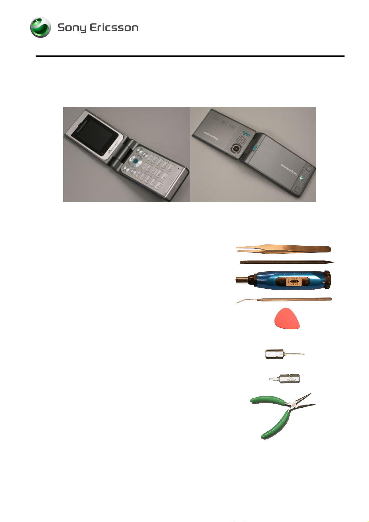
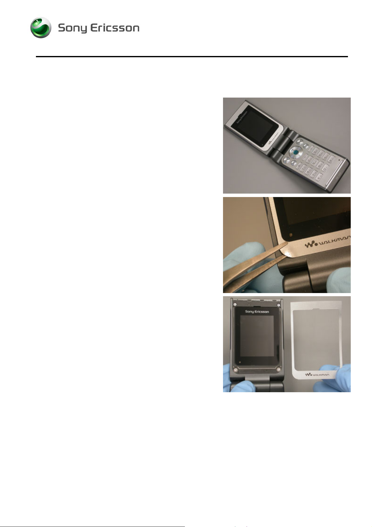
1.1 View of W380
1.2 Tools and Equipment
The following tools and equipment should be available while performing the procedures.
STANDARD TOOLS
• Style 2A Tweezers – Rounded Tip
• Nylon Pointer
• Torque Driver
• Dental Hook
• Plectrum
PRODUCT SPECIFIC TOOLS
• JCIS No. 0 Screw Bit
• T6 screw bit
• Pliers
1208-3927 2
Company Internal
Communications AB
© Sony Ericsson Mobile
3(79)
Page 4
Working Instruction, Mechanical
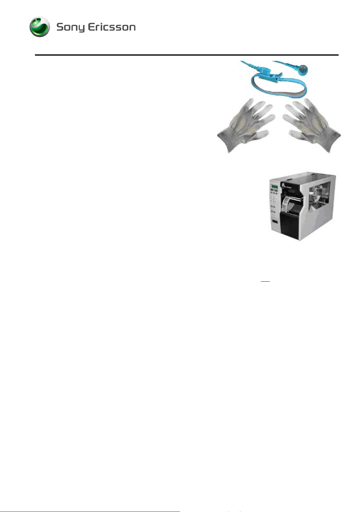
ESD EQUIPMENT
Protect the phone from ESD damage whenever it has been
opened:
Minimum requirements are:
• ESD wristband
• ESD gloves
• ESD mat
LABEL EQUIPMENT
The following special equipment is required when replacing
or installing a new label:
• Zebra printer connected to computer
1.3 General Cautions
The following cautions are considered to be generic for all products and will not be repeated in the
Disassembly, Reassembly, and Replacements sections:
• S
WITCH OFF THE PHONE AND REMOVE ANY MEMORY STICK BEFORE THE START OF THE DISASSEMBLY!
• K
EEP ALL CONTACT SURFACES CLEAN!
• B
E CAREFUL WHEN USING TOOLS LIKE THE DENTIST HOOK, TWEEZERS, PRY TOOLS, ETC. TO AVOID
SCRATCHES OR DAMAGE TO THE EXTERIOR AND INTERIOR PARTS OF THE PHONE!
E CAREFUL NOT TO DAMAGE ANY CONTACT SPRINGS!
• B
• R
EMEMBER TO REMOVE THE PROTECTION FILMS ON NEW PARTS SUCH AS THE FRONT COVER AND LCD!
EVER TOUCH THE DISPLAY GLASS!
• N
1.4 Adhesives
Use a dentist hook, the tweezers, and/or a nylon pointer to remove old adhesives.
Clean the surface with isopropyl alcohol before attaching new adhesives.
1.5 Using Hand and ESD Protection
When handling this product, keep all surfaces clean of dirt, dust, debris, and hand oil. Use
appropriate ESD precautions when working on this product. The use of finger cots or gloves, an ESD
mat, and an ESD wrist strap are required at minimum.
1208-3927 2
© Sony Ericsson Mobile Communications AB
4(79)
Page 5

Working Instruction, Mechanical
1.6 Protection of Displays, Lenses, and Windows
Any time the screen portion of a display assembly, the windows of a display cover, or a camera lens
is unprotected and exposed, add a protective film over the exposed part to reduce the amount of
dust, finger prints, debris, and/or damage that the part may obtain.
1.7 Acceptable Pry Tools
Whenever the phrase “pry tool” is used, a nylon pointer, a plectrum, or a front opening tool may be
used depending on the user’s preference.
1208-3927 2
© Sony Ericsson Mobile Communications AB
5(79)
Page 6
Working Instruction, Mechanical
2 Disassembly
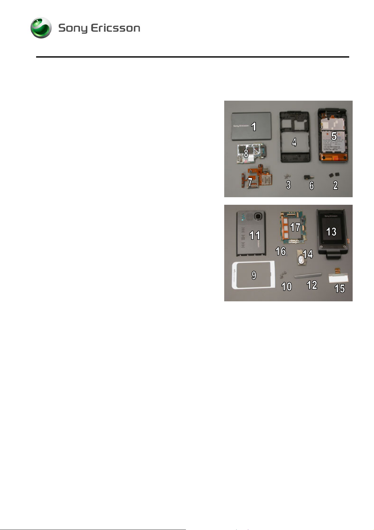
2.1 Overview
Disassemble in the following order:
Lower Half
• Battery Cover (1)
• Battery
• Screw covers (2)
• Lower back screws (3)
• Lower back cover (4) from lower front (5)
• Vibrator (6)
• SIM/M2 Flex (7)
• Lower PCB (8)
Upper Half
• Main window label (9)
• Upper front screws (10)
• Upper back cover (11) and cover light panel assembly
(12) from upper front (13)
• Loudspeaker (14)
• Outer display (15)
• Upper PBA screws (16) and upper PBA (17) from upper
front (13)
1208-3927 2
Company Internal
Communications AB
© Sony Ericsson Mobile
6(79)
Page 7
Working Instruction, Mechanical
Lower Half
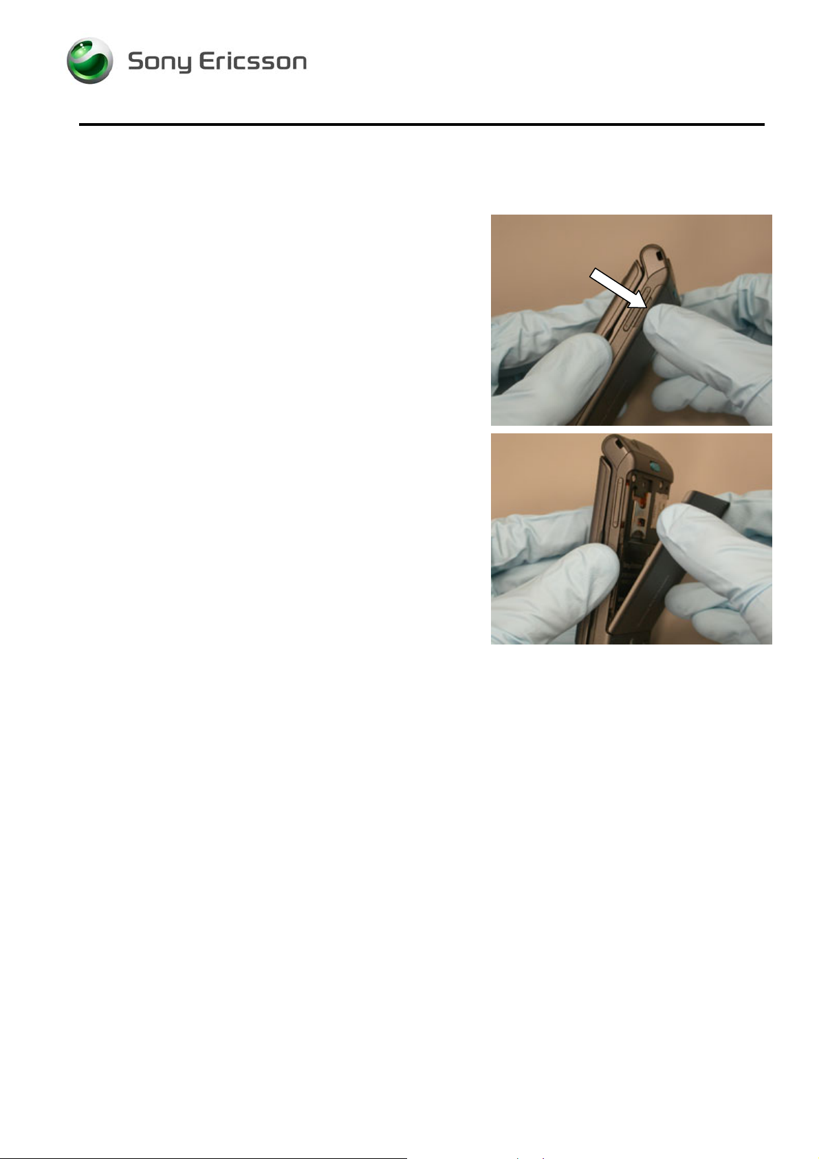
2.1.1 Battery Cover Removal
Lift up on the battery cover at its notch.
Remove battery cover.
1208-3927 2
Company Internal
Communications AB
© Sony Ericsson Mobile
7(79)
Page 8
Working Instruction, Mechanical
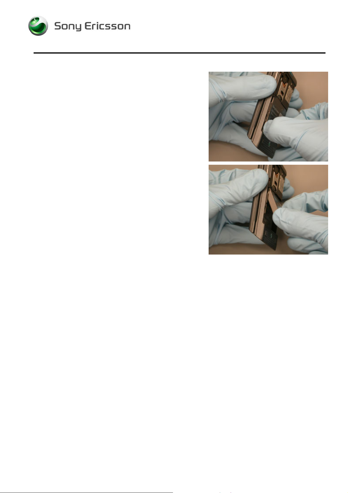
2.1.2 Battery Removal
Lift up on the lower sides of the battery from the notches.
Remove battery.
1208-3927 2
© Sony Ericsson Mobile Communications AB
8(79)
Page 9
Working Instruction, Mechanical
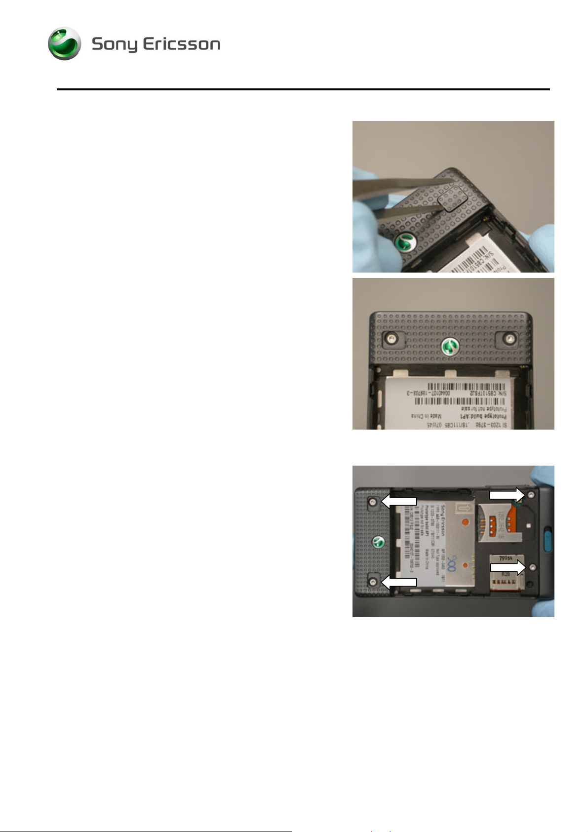
2.1.3 Screw Cover Removal
Pry the screw cover off from the short side using the round
tipped tweezers.
N
OTE: DO NOT REUSE SCREW COVERS
Pry the other screw cover off using round tipped tweezers.
N
OTE: ENSURE NO ADHESIVE RESIDUE REMAINS IN THE
SCREW RECESS.
2.1.4 Lower Back Screw Removal
Remove the 4 screws using a T5 bit.
1208-3927 2
© Sony Ericsson Mobile Communications AB
9(79)
Page 10
Working Instruction, Mechanical
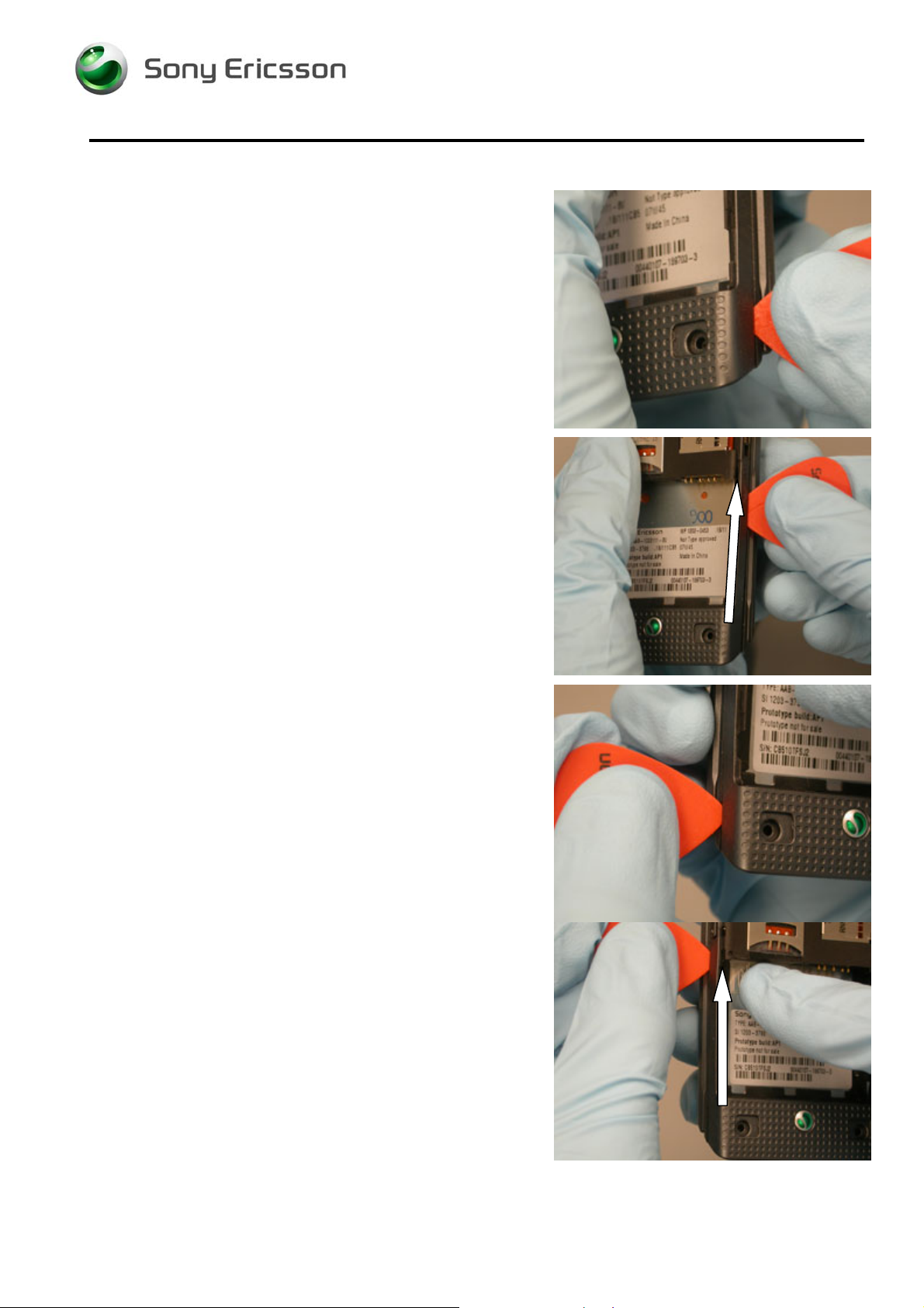
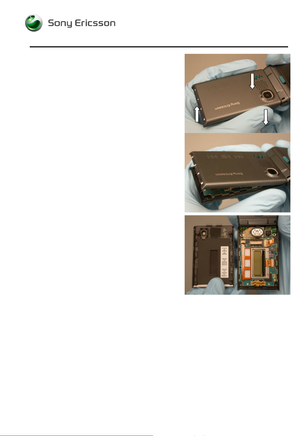
2.1.5 Lower Back Cover Removal
Insert the plectrum between the lower rear cover and the
lower front cover just below the battery cavity.
Slide the plectrum along the seam up to the system
connector or volume key to release the latches.
Repeat for the other side.
1208-3927 2
© Sony Ericsson Mobile Communications AB
10(79)
Page 11
Working Instruction, Mechanical
Insert the plectrum between the lower rear cover and the
SIM card reader as shown and unlatch the tabs.
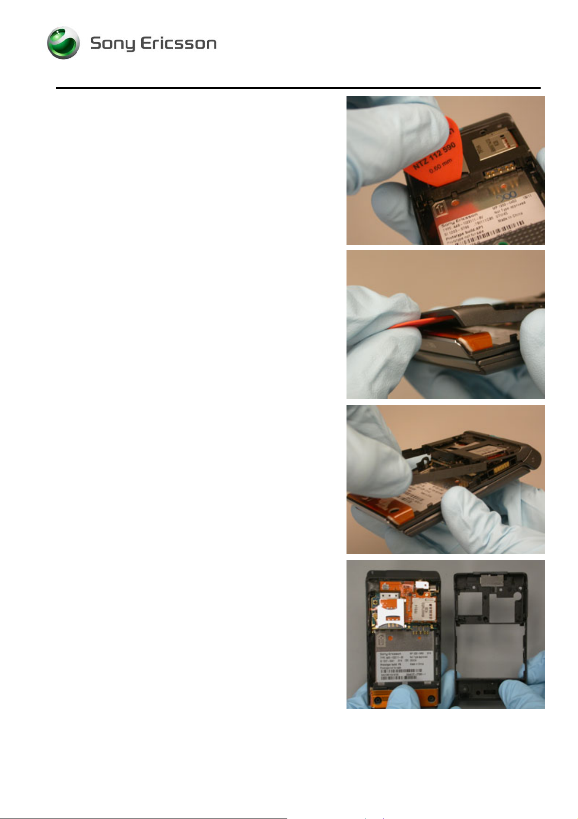
Use the plectrum to separate the lower rear cover from the
antenna.
Lift up on the lower end of the lower rear cover.
Remove the lower rear cover.
1208-3927 2
© Sony Ericsson Mobile Communications AB
11(79)
Page 12
Working Instruction, Mechanical
2.1.6 Vibrator Removal
Lift up on the vibrator cap by inserting the round tipped
tweezers between the flex and the vibrator.
Pull the vibrator out of its housing.
1208-3927 2
© Sony Ericsson Mobile Communications AB
12(79)
Page 13
Working Instruction, Mechanical
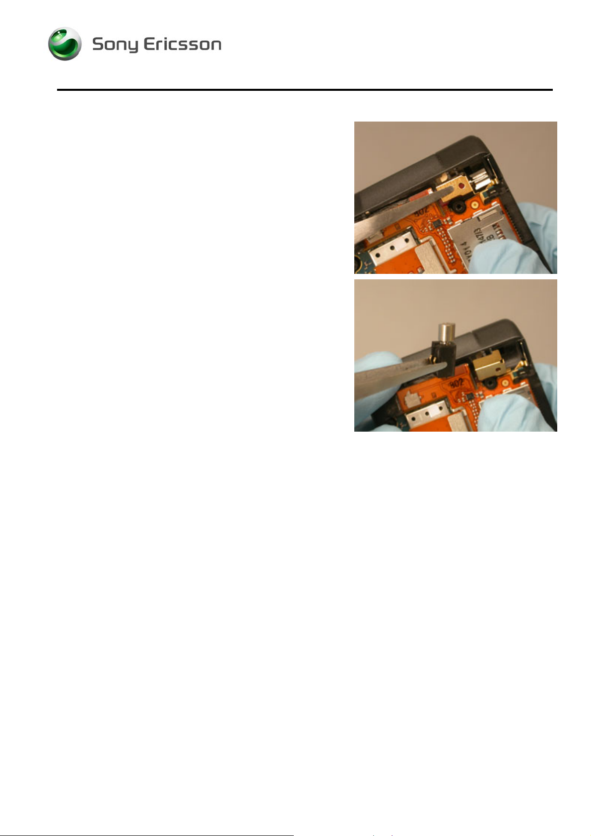
2.1.7 SIM/M2 Flex Removal
Carefully detach the ESD Cushion from the PCB by
wedging up on the edge shown using round tipped
tweezers.
OTE: THE ESD CUSHION ADHESIVE MAY TEAR OFF IF NOT
N
REMOVED PROPERLY
Remove the ESD cushion.
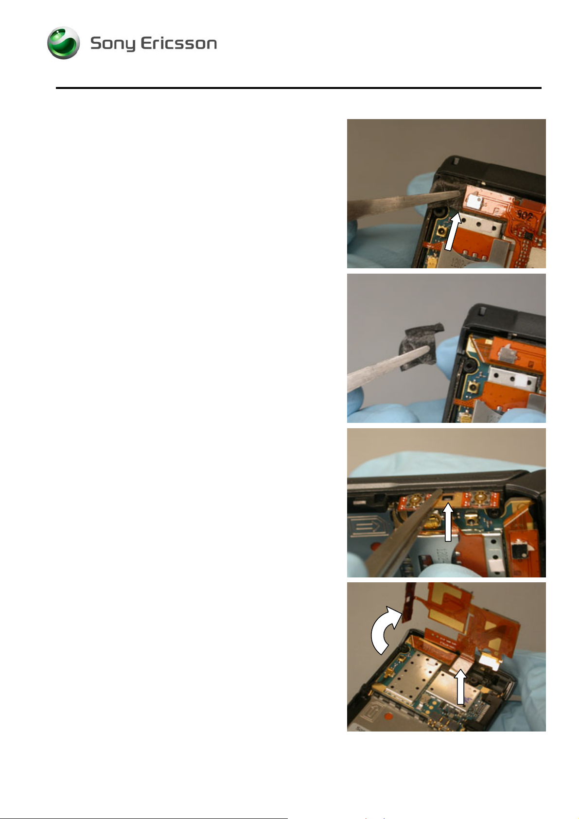
Using the round tipped tweezers, release the side key
portion of the SIM/M2 flex from its positioning latch and lift it
from the lower front cover.
Rotate the SIM/M2 flex up from the circuit board as shown
to expose the flex connector.
1208-3927 2
© Sony Ericsson Mobile Communications AB
13(79)
Page 14
Working Instruction, Mechanical
Separate the flex connector from the PCB by prying with the
pry tool.
N
OTE: DO NOT DAMAGE THE ESD GASKET
Remove the SIM/M2 flex.
1208-3927 2
© Sony Ericsson Mobile Communications AB
14(79)
Page 15
Working Instruction, Mechanical
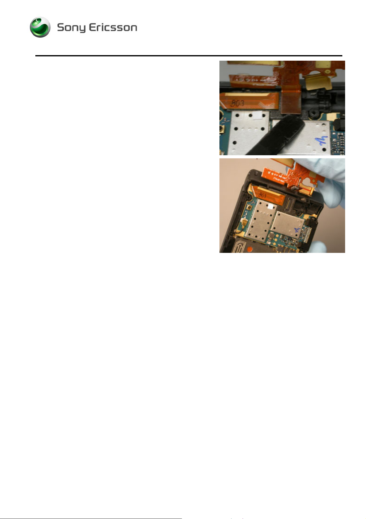
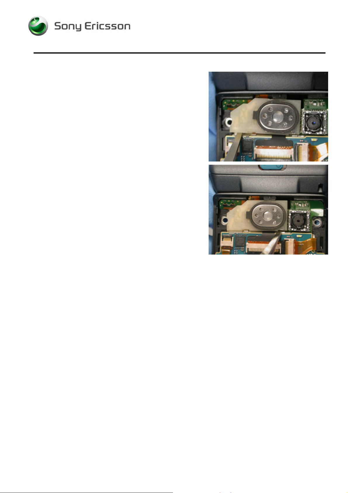
2.1.8 Lower PCB Removal
Pry the flex connector off of the lower PCB using a pry tool.
N
OTE: DO NOT DAMAGE THE ESD GASKET
Remove the ESD gasket using round tipped tweezers.
Disconnect the coax cable.
Pry in the location shown to release the first latch.
1208-3927 2
© Sony Ericsson Mobile Communications AB
15(79)
Page 16
Working Instruction, Mechanical
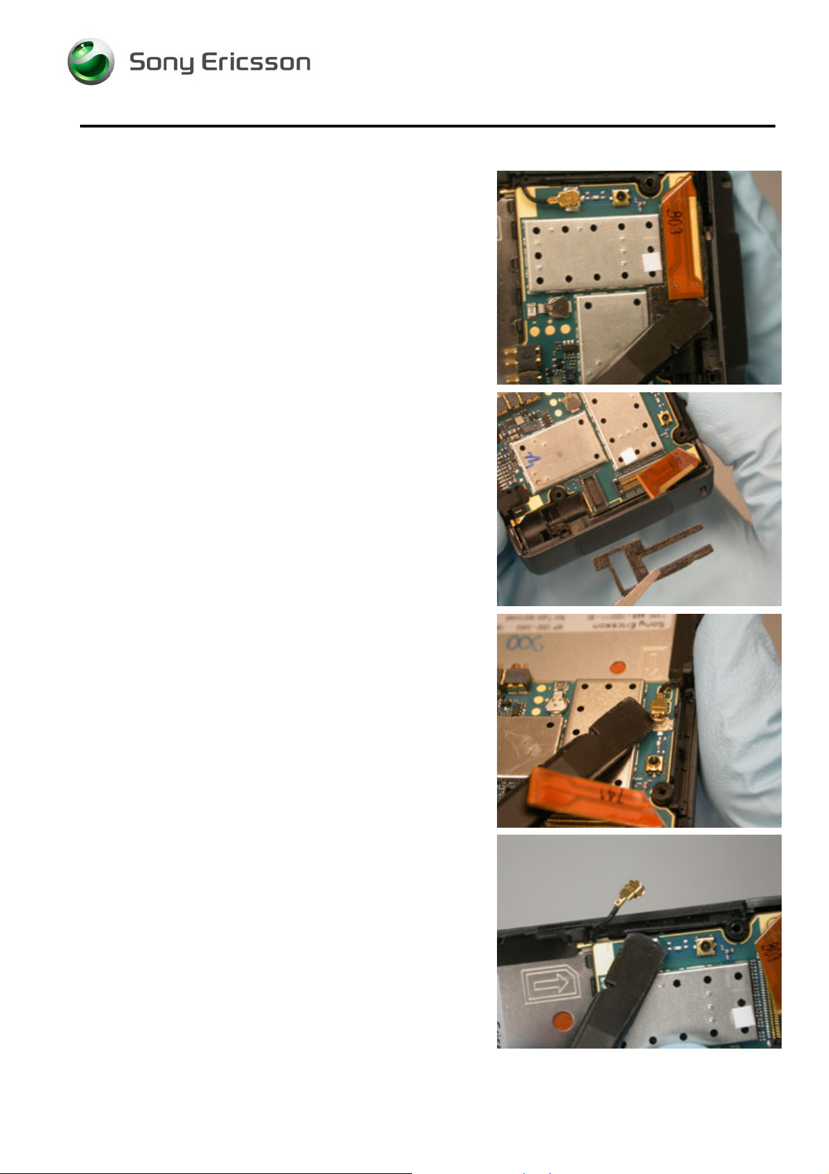
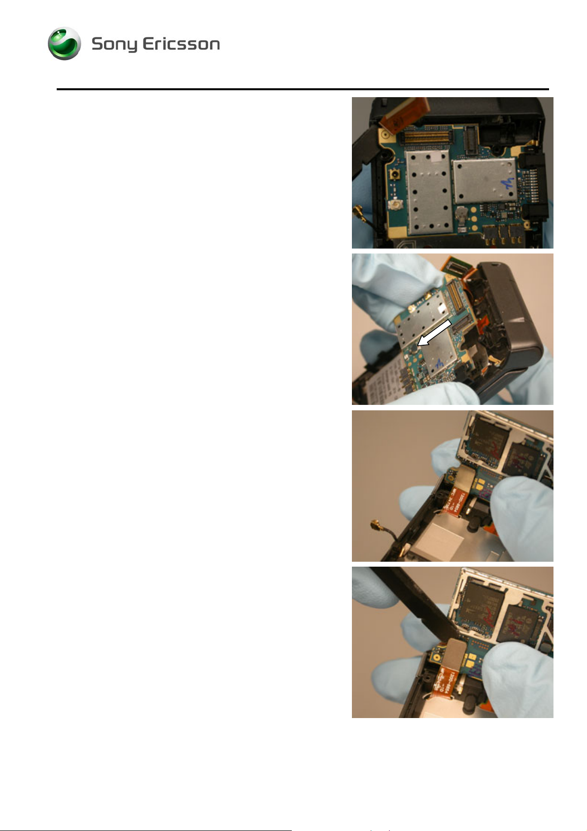
Pry in the location shown to lift the PCB.
Pull the PCB away as shown.
Rotate the PCB away from the lower inner cover so that you
can see the underside.
Unplug the keyboard flex from the PCB using a pry tool.
1208-3927 2
© Sony Ericsson Mobile Communications AB
16(79)
Page 17
Working Instruction, Mechanical
Upper Half
2.1.9 Main Window Label Removal
Open the phone.
Pry the edge of the gasket up with the round tipped
tweezers as shown.
Peel the gasket off the upper front cover.
1208-3927 2
© Sony Ericsson Mobile Communications AB
17(79)
Page 18
Working Instruction, Mechanical
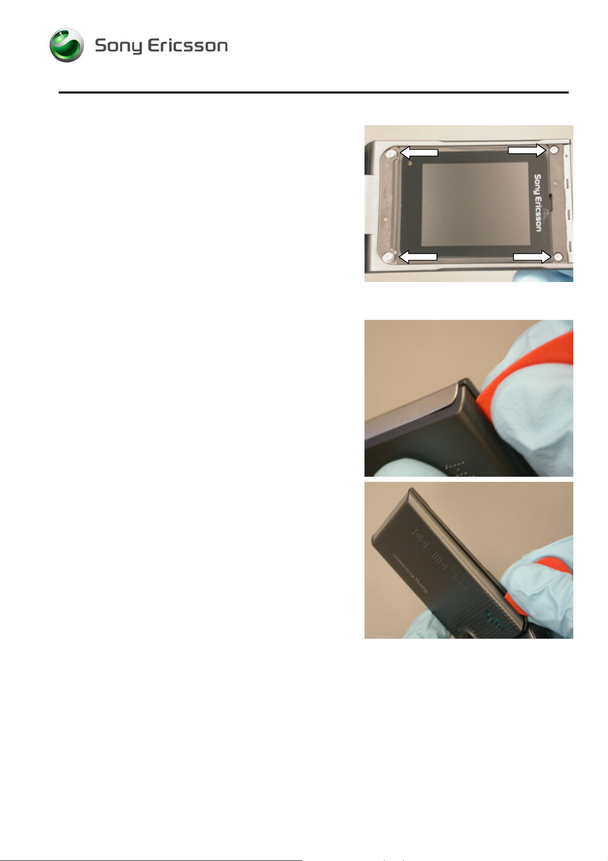
2.1.10 Upper Front Screw Removal
Remove the 4 screws shown using a T5 bit.
2.1.11 Upper Back Cover Removal
Insert the plectrum between the upper back and upper front
covers at the top of the phone. Angle the plectrum and
push it into the seam.
Slide the plectrum along the seam to release the three side
latches.
1208-3927 2
© Sony Ericsson Mobile Communications AB
18(79)
Page 19
Working Instruction, Mechanical
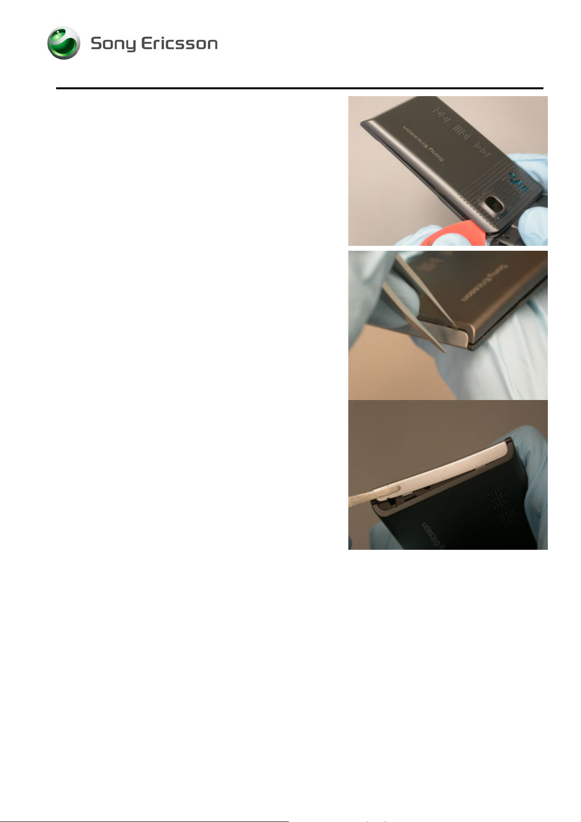
Repeat for the other side.
Pry one end of the cover light panel assembly free using
round tipped tweezers.
Grip the free end of the cover light panel assembly and pull
it off the phone.
OTE: DO NOT REUSE COVER LIGHT PANEL
N
1208-3927 2
© Sony Ericsson Mobile Communications AB
19(79)
Page 20
Working Instruction, Mechanical
Hold the phone as shown. Pull down with your index finger
and thumb while pushing up with your hand to release the
end latch.
Remove upper rear cover.
1208-3927 2
© Sony Ericsson Mobile Communications AB
20(79)
Page 21
Working Instruction, Mechanical
2.1.12 Loudspeaker Removal
Pry the loudspeaker up in the location shown using round
tipped tweezers.
Pry the loudspeaker out in the location shown using round
tipped tweezers.
NOTE:
FEATURES
BE CAREFUL NOT TO DAMAGE METAL HOLDER
1208-3927 2
© Sony Ericsson Mobile Communications AB
21(79)
Page 22
Working Instruction, Mechanical
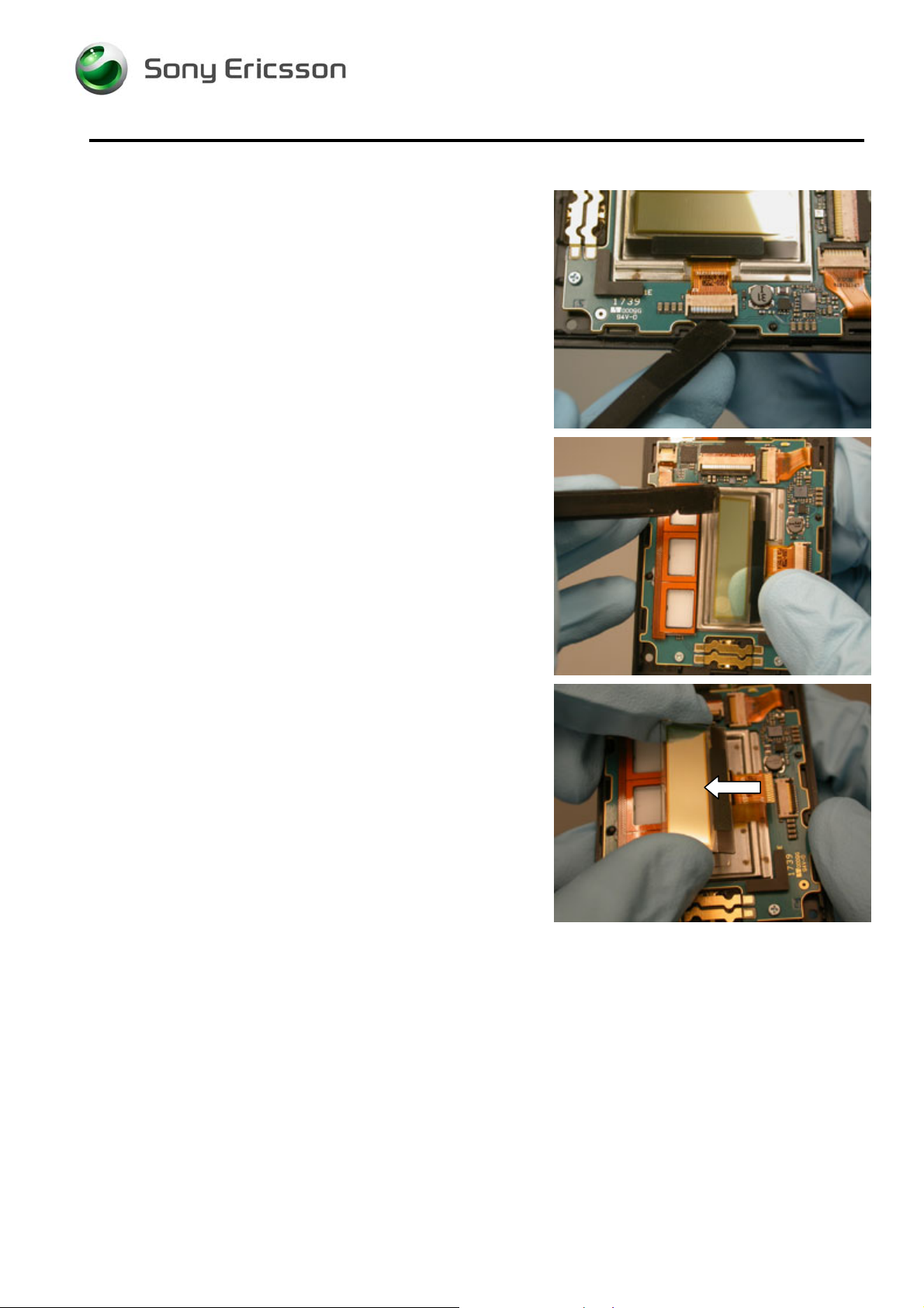
2.1.13 Outer Display Removal
Flip the bar of the ZIF connector up using a pry tool.
Lift up on the display with a pry tool so that you can grab
the sides.
Remove the display.
1208-3927 2
© Sony Ericsson Mobile Communications AB
22(79)
Page 23
Working Instruction, Mechanical
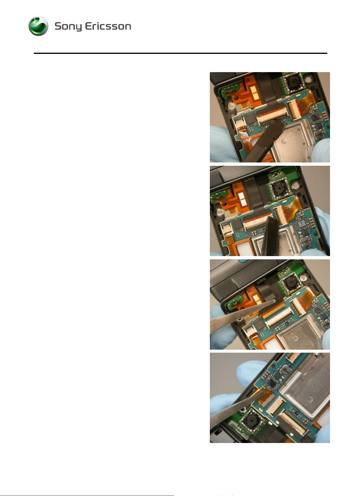
2.1.14 Upper PBA Removal
Open the hinge flex ZIF connector.
Open the display ZIF connector.
Carefully pull the flex out of the hinge ZIF connector using
round tipped tweezers.
Carefully pull the flex out of the display ZIF connector using
round tipped tweezers.
1208-3927 2
© Sony Ericsson Mobile Communications AB
23(79)
Page 24
Working Instruction, Mechanical
Remove the two upper PBA screws using a JCIS No. 0 bit.
Lift on the lower end of the PBA and remove it from the
upper front cover.
1208-3927 2
© Sony Ericsson Mobile Communications AB
24(79)
Page 25

Working Instruction, Mechanical
3 Replacement
3.1 Antenna Assembly Replacement
Complete 2.1.1-2.1.5 of the disassembly instructions.
Remove the ESD cushion.
Removal
Using the round tipped tweezers, release the side key
portion of the SIM/M2 flex from its positioning latch and lift it
from the lower front cover.
Lift up on the vibrator clip.
1208-3927 2
Company Internal
Communications AB
© Sony Ericsson Mobile
25(79)
Page 26

Working Instruction, Mechanical
Lift up on the flex to expose the lower PCB.
Disconnect the coax cable from the lower PCB
Remove the coax cable gasket.
Pry the antenna off the lower front cover.
1208-3927 2
© Sony Ericsson Mobile Communications AB
26(79)
Page 27

Working Instruction, Mechanical
Installation
Obtain a new antenna assembly.
Snap the new antenna into position.
Lay the coax cable into the groove.
NOTE: DO NOT REUSE THE COAX CABLE GASKET
Position the coax cable gasket over the cable so that the
notches on the gasket align with the features along the
edge of the lower front cover.
1208-3927 2
© Sony Ericsson Mobile Communications AB
27(79)
Page 28

Working Instruction, Mechanical
Connect the coax cable to the PCB and position the
connection so that it oriented as shown.
Position the volume key flex around the tab shown using
the round tipped tweezers.
Complete 4.1.10-4.1.14 of the reassembly procedure.
3.2 Battery Cover Replacement
Removal
Complete 2.1.1 of the disassembly procedure.
Installation
Obtain a new battery cover.
Complete 4.1.14 of the reassembly procedure.
3.3 Camera Replacement
See 3.10 Hinge FPC Replacement
1208-3927 2
© Sony Ericsson Mobile Communications AB
28(79)
Page 29

Working Instruction, Mechanical
3.4 Coax Cable Gasket Replacement
Complete 2.1.1-2.1.2 of the disassembly procedure.
Removal
Remove the coax cable gasket using round tipped
tweezers.
Installation
Obtain a new coax cable gasket.
Position the coax cable gasket over the cable so that the
notches on the gasket align with the features along the
edge of the lower front cover.
Complete 4.1.13-4.1.14 of the reassembly procedure.
1208-3927 2
© Sony Ericsson Mobile Communications AB
29(79)
Page 30

Working Instruction, Mechanical
3.5 Co-brand Inlay Assembly Replacement
Removal
Lift up on the co-brand label with round tipped tweezers to
separate the keyboard from the dome foil.
Peel the keyboard off the phone.
1208-3927 2
© Sony Ericsson Mobile Communications AB
30(79)
Page 31

Working Instruction, Mechanical
Installation
Obtain a new keyboard and co-brand label.
Place the co-brand label on the phone as shown and apply
pressure over the surface so a good bond forms.
Line the bottom of the keyboard up with the co-brand label.
Lay the keyboard in the recessed area on the phone and
apply pressure around the edge of the keyboard as shown
so that a good bond forms.
1208-3927 2
© Sony Ericsson Mobile Communications AB
31(79)
Page 32

Working Instruction, Mechanical
3.6 Cover Light Panel Replacement
Complete the removal portion of 3.20 Main Window Label
Replacement.
Removal
Pry one end of the cover light panel free using round tipped
tweezers.
Grip the free end of the cover light panel and pull it off the
phone.
Installation
Obtain a new cover light panel.
1208-3927 2
© Sony Ericsson Mobile Communications AB
32(79)
Page 33

Working Instruction, Mechanical
Place the cover light panel over the end of the phone so
that the four positioning features line up.
Then press the two tabs under the upper rear cover.
Complete the installation portion of 3.20 Main Window
Label Replacement.
1208-3927 2
© Sony Ericsson Mobile Communications AB
33(79)
Page 34

Working Instruction, Mechanical
3.7 Ear Speaker Replacement
Complete 2.1.1-2.1.2 and 2.1.9-2.1.14 of the disassembly
procedure.
Removal
Pry the ear speaker out from the side shown using a pair of
round tipped tweezers.
N
OTE: BE SURE TO REMOVE ANY ADHESIVE RESIDUE
Installation
Obtain a new ear speaker.
Place the ear speaker in the position shown.
N
OTE: DO NOT PRESS ON THE SPRING FINGERS
Complete 4.1.1-4.1.6 and 4.1.13-4.1.14 of the reassembly
procedure.
1208-3927 2
© Sony Ericsson Mobile Communications AB
34(79)
Page 35

Working Instruction, Mechanical
3.8 Flex Plug Replacement
Complete 2.1.1-2.1.8 of the disassembly procedure.
Removal
Pry the flex plug with round tipped tweezers using the frame
for leverage as shown.
Pull the flex plug out.
1208-3927 2
© Sony Ericsson Mobile Communications AB
35(79)
Page 36

Working Instruction, Mechanical
Installation
Obtain a new flex plug.
Position the flex as shown and insert the plug.
Complete 4.1.7-4.1.14 of the reassembly procedure.
1208-3927 2
© Sony Ericsson Mobile Communications AB
36(79)
Page 37

Working Instruction, Mechanical
3.9 Hinge Replacement
Complete 2.1.1-2.1.8 of the disassembly procedure.
Complete the removal portion of 3.11 Hinge Plug
Replacement.
Removal
Grip the sides of the hinge with a pair of needle-nose pliers
and remove it.
Installation
Obtain a new hinge.
1208-3927 2
© Sony Ericsson Mobile Communications AB
37(79)
Page 38

Working Instruction, Mechanical
Insert the hinge using needle-nose pliers with the
orientation shown.
N
OTE: THE NOTCH IN THE HINGE SHOULD FACE THE TAB
WITHIN THE HINGE CAVITY
Complete the installation portion of 3.11 Hinge Plug
Replacement.
Complete 4.1.7-4.1.14 of the reassembly procedure.
1208-3927 2
© Sony Ericsson Mobile Communications AB
38(79)
Page 39

Working Instruction, Mechanical
3.10 Hinge FPC Replacement
Complete 2.1.1-2.1.12 of the disassembly instructions.
Complete the removal portion of 3.8, 3.11, and 3.9.
Removal
Open the hinge FPC ZIF connector.
Pull the flex out using round tipped tweezers.
Lift the hinge FPC off the frame.
1208-3927 2
© Sony Ericsson Mobile Communications AB
39(79)
Page 40

Working Instruction, Mechanical
Wiggle the two phone halves carefully to separate them.
Feed the hinge flex through the cavity in the lower half.
Rotate the flex connector away from you so that you see
the back.
Pull the flex through far enough that you can flip the FPC
over
1208-3927 2
© Sony Ericsson Mobile Communications AB
40(79)
Page 41

Working Instruction, Mechanical
Rotate the connector towards you so that you see the green
side.
Feed the flex through.
Installation
Obtain a new hinge FPC.
Carefully feed the flex connector into the hinge.
Pull the flex through the hinge.
1208-3927 2
© Sony Ericsson Mobile Communications AB
41(79)
Page 42

Working Instruction, Mechanical
Feed the connector through the hinge of the lower half.
Snap the two halves together.
Insert the hinge flex into the ZIF connector.
Close the connector.
Complete the installation portion of 3.9, 3.11, and 3.8.
Complete 4.1.3-4.1.14 of the reassembly instructions.
1208-3927 2
© Sony Ericsson Mobile Communications AB
42(79)
Page 43

Working Instruction, Mechanical
3.11 Hinge Plug Replacement
Complete 2.1.1-2.1.8 of the disassembly procedure.
Removal
Insert the tip of the round tipped tweezers into the opening
shown.
Pry the hinge plug out.
1208-3927 2
© Sony Ericsson Mobile Communications AB
43(79)
Page 44

Working Instruction, Mechanical
Grip the hinge plug with the tweezers as shown and remove
it.
Installation
Obtain a new hinge plug.
Open the phone.
1208-3927 2
© Sony Ericsson Mobile Communications AB
44(79)
Page 45

Working Instruction, Mechanical
Insert the hinge plug into the hinge frame.
Complete 4.1.8-4.1.14 of the reassembly procedure.
3.12 Keyboard Replacement
Removal
Lift up on the co-brand label with round tipped tweezers to
separate the keyboard from the dome foil.
Peel the keyboard off the dome foil.
1208-3927 2
© Sony Ericsson Mobile Communications AB
45(79)
Page 46

Working Instruction, Mechanical
Installation
Obtain a new keyboard and co-brand label.
Place the co-brand label on the phone.
Line the bottom of the keyboard up with the co-brand label.
Lay the keyboard across the phone and press firmly to
create a good bond.
1208-3927 2
© Sony Ericsson Mobile Communications AB
46(79)
Page 47

Working Instruction, Mechanical
3.13 Keyboard FPC Assembly Replacement
Complete 2.1.1-2.1.8 of the disassembly procedure.
Complete the removal portions of 3.5.
Removal
Use the round tipped tweezers to pry the microphone up.
Starting from the bottom right corner, peel the keypad FPC
off the lower front cover.
Remove any remaining adhesive.
1208-3927 2
© Sony Ericsson Mobile Communications AB
47(79)
Page 48

Working Instruction, Mechanical
Installation
Obtain a new keypad FPC.
Insert the connector end and tab into the corresponding
slots.
Line the top of the keypad FPC up with the recess and
smooth the keypad across the phone.
Snap the microphone flex down into the recess.
Complete the installation portions of 3.5.
Complete 4.1.8-4.1.14 of the reassembly instructions.
1208-3927 2
© Sony Ericsson Mobile Communications AB
48(79)
Page 49

Working Instruction, Mechanical
3.14 Key Locking Assembly Replacement
Complete 2.1.1-2.1.5 of the disassembly procedure.
Remove the key locking assembly cover using round tipped
tweezers.
Removal
Remove the key locking assembly with a pair of round
tipped tweezers. Flex the top of the lower back cover to
release the tab.
Installation
Obtain a new key locking assembly.
Insert the key locking assembly.
N
OTE: ENSURE THE TAB LATCHES
1208-3927 2
© Sony Ericsson Mobile Communications AB
49(79)
Page 50

Working Instruction, Mechanical
Insert the keylock cover tab into the gap and snap the cover
into place.
Complete 4.1.11-4.1.14 of the reassembly procedure.
1208-3927 2
© Sony Ericsson Mobile Communications AB
50(79)
Page 51

Working Instruction, Mechanical
3.15 Label Replacement
Complete 2.1.1-2.1.2 of the disassembly procedure.
Removal
Peel up a corner of the label using round tipped tweezers
and remove the label.
Installation
Print a new label.
Align the corner of the label as shown.
Smooth the label out onto the surface.
Complete 4.1.13-4.1.14 of the reassembly procedure.
1208-3927 2
© Sony Ericsson Mobile Communications AB
51(79)
Page 52

Working Instruction, Mechanical
3.16 Loudspeaker Replacement
Complete 2.1.1-2.1.2 and 2.1.9-2.1.12 of the disassembly
procedure.
Installation
Obtain a new loudspeaker.
Complete 4.1.3-4.1.6 and 4.1.13-4.1.14 of the reassembly
procedure.
3.17 Lower Back Cover Replacement
Complete 2.1.1-2.1.5 of the disassembly procedure.
Installation
Obtain a new lower back cover.
Complete 4.1.11-4.1.14 of the reassembly procedure.
3.18 Liquid Intrusion Indicator Replacement
Complete 2.1.1-2.1.7 of the disassembly procedure.
Removal
Remove the liquid intrusion indicator with round tipped
tweezers.
Installation
Obtain a new liquid intrusion indicator.
Place the indicator as shown.
Complete 4.1.9-4.1.14 of the reassembly procedure.
1208-3927 2
© Sony Ericsson Mobile Communications AB
52(79)
Page 53

Working Instruction, Mechanical
3.19 Lower Front Cover Replacement
Complete 2.1.1-2.1.8 of the disassembly procedure.
Complete the removal portions of 3.1, 3.8, 3.11 and 3.9.
Removal
Carefully wiggle the two halves apart.
Feed the hinge flex through the hinge cavity.
Installation
Obtain a new lower front cover assembly.
Feed the hinge flex through the hinge cavity.
1208-3927 2
© Sony Ericsson Mobile Communications AB
53(79)
Page 54

Working Instruction, Mechanical
Snap the two phone halves together.
Complete the installation portions of 3.9, 3.11, 3.8, and 3.1.
Complete 4.1.7-4.1.14 of the reassembly procedure.
3.20 Main Window Label Replacement
Complete 2.1.1-2.1.2 and 2.1.9 of the disassembly section.
Installation
Obtain a new main window label.
Complete 4.1.6 and 4.1.13-4.1.14 of the reassembly
section.
3.21 Outer Display Replacement
Complete 2.1.1-2.1.2 and 2.1.9-2.1.13 of the disassembly
procedure.
Installation
Obtain a new outer display.
Complete 4.1.2-4.1.6 and 4.1.13-4.1.14 of the reassembly
procedure.
3.22 Screw Cover Replacement
Complete 2.1.1-2.1.3 of the disassembly procedure.
Installation
Obtain a new screw cover.
Complete 4.1.12-4.1.14 of the reassembly procedure.
1208-3927 2
© Sony Ericsson Mobile Communications AB
54(79)
Page 55

Working Instruction, Mechanical
3.23 SIM Flex Replacement
Complete 2.1.1-2.1.7 of the disassembly section.
Installation
Obtain a new SIM flex and vibrator cap.
Peel the backing off the adhesive flex strip.
Place the flex strip into the vibrator cap.
Complete 4.1.9-4.1.14 of the reassembly section.
N
OTE: BE SURE TO REPLACE THE ESD CUSHION
1208-3927 2
© Sony Ericsson Mobile Communications AB
55(79)
Page 56

Working Instruction, Mechanical
3.24 T ouch Key Assembly Replacement
Complete 2.1.1-2.1.2 and 2.1.9-2.1.11 of the disassembly
procedure.
Removal
Flip the ZIF connector open using round tipped tweezers.
Carefully pull the flex out of the connector as shown.
Peel the touch keys off the upper PBA.
Installation
Obtain a new touch key assembly.
1208-3927 2
© Sony Ericsson Mobile Communications AB
56(79)
Page 57

Working Instruction, Mechanical
Line the LEDs on the PBA up with the ports on the back of
the touch keys.
Adhere the touch keys to the PBA.
N
OTE: THE TOUCH KEY ASSEMBLY SHOULD CLEAR THE
ALIGNMENT PEG
Insert the flex into the connector using round tipped
tweezers as shown.
Close the ZIF connector.
Complete 4.1.4-4.1.6 and 4.1.13-4.1.14 of the reassembly
procedure.
1208-3927 2
© Sony Ericsson Mobile Communications AB
57(79)
Page 58

Working Instruction, Mechanical
3.25 Upper Back Cover Replacement
Complete 2.1.1-2.1.2 and 2.1.9-2.1.11 of the disassembly
procedure.
Installation
Obtain a new upper back cover.
Complete 4.1.4-4.1.6 and 4.1.13-4.1.14 of the reassembly
procedure.
3.26 Upper Front Assembly Replacement
Complete 2.1.1-2.1.14 of the disassembly instructions.
Complete the removal portion 3.8, 3.11, and 3.9.
Removal
Wiggle the two phone halves carefully to separate them.
Feed the hinge flex through the cavity in the lower half.
1208-3927 2
© Sony Ericsson Mobile Communications AB
58(79)
Page 59

Working Instruction, Mechanical
Rotate the flex connector towards from you so that you see
the back.
Pull the flex through far enough that you can flip the FPC
over
Rotate the connector towards you so that you see the green
side.
Feed the flex through.
Installation
Obtain a new hinge FPC.
1208-3927 2
© Sony Ericsson Mobile Communications AB
59(79)
Page 60

Working Instruction, Mechanical
Carefully feed the flex connector into the hinge.
Pull the flex through the hinge.
Feed the connector through the hinge of the lower half.
Snap the two halves together.
Complete the installation portion of 3.8, 3.9, and 3.11.
Complete 4.1.4-4.1.14 of the reassembly instructions.
1208-3927 2
© Sony Ericsson Mobile Communications AB
60(79)
Page 61

Working Instruction, Mechanical
3.27 Upper PBA Replacement
Complete 2.1.1-2.1.2 and 2.1.9-2.1.14 of the disassembly
procedure.
Installation
Obtain a new upper PBA.
Complete 4.1.1-4.1.6 and 4.1.13-4.1.14 of the reassembly
procedure.
3.28 Vibrator Replacement
Complete 2.1.1-2.1.6 of the disassembly procedure.
Installation
Obtain a new vibrator.
Complete 4.1.9-4.1.14 of the reassembly procedure.
3.29 Volume Key Replacement
Complete 2.1.1-2.1.5 of the disassembly procedure.
Removal
Push the volume key in as shown.
Grip the volume key with round tipped tweezers.
1208-3927 2
© Sony Ericsson Mobile Communications AB
61(79)
Page 62

Working Instruction, Mechanical
Remove the key.
Installation
Obtain a new volume key.
Insert the back of the key in front of the tab on the back
cover.
Push the key into place.
Complete 4.1.10-4.1.14 of the reassembly procedure.
1208-3927 2
© Sony Ericsson Mobile Communications AB
62(79)
Page 63

Working Instruction, Mechanical
4 Reassembly
4.1 Overview
Reassemble in the following order:
Upper Half
• Upper PBA (2) and Upper PBA screws (1) to Upper
Front (6)
• Outer Display (3)
• Loudspeaker (4)
• Upper Back Cover (5) to Upper Front (6)
• Cover Light Panel Assembly (7)
• Upper Front Screws (8)
• Main Window Label (9)
Lower Half
• Lower PCB (10)
• Vibrator (11)
• SIM/M2 Flex (12)
• Lower Back Cover (13) to Lower Front (14)
• Lower Back Screws (15)
• Screw Covers (16)
• Battery
• Battery Cover (17)
1208-3927 2
Company Internal
Communications AB
© Sony Ericsson Mobile
63(79)
Page 64

Working Instruction, Mechanical
4.1.1 Upper PBA Installation
Insert the board under the tab shown.
Lay the board down onto the frame using the alignment
pegs.
NOTE:
ARE NOT UNDER THE BOARD
Insert two inner screws in the locations shown. Tighten to 9
Ncm using a JCIS-0 bit.
MAKE SURE THE HINGE FLEX AND MAIN DISPLAY FLEX
1208-3927 2
© Sony Ericsson Mobile Communications AB
64(79)
Page 65

Working Instruction, Mechanical
Insert the hinge flex into the ZIF connector on the PCB
using round tipped tweezers.
Close the ZIF connector.
Insert the display flex into the ZIF connector.
Close the ZIF connector.
1208-3927 2
© Sony Ericsson Mobile Communications AB
65(79)
Page 66

Working Instruction, Mechanical
4.1.2 Outer Display Installation
Peel off the outer display adhesive using round tipped
tweezers.
Place a new outer display adhesive in the recess, lining the
edge up as shown.
Lay the adhesive flat out over the recess.
Insert the outer display flex into the ZIF connector as
shown.
1208-3927 2
© Sony Ericsson Mobile Communications AB
66(79)
Page 67

Working Instruction, Mechanical
Lay the outer display into place on the upper front cover as
shown.
Close the ZIF connector.
1208-3927 2
© Sony Ericsson Mobile Communications AB
67(79)
Page 68

Working Instruction, Mechanical
4.1.3 Loudspeaker Installation
Insert the tabbed end of the loudspeaker under tab at hinge
opening.
Press down on the edge of the loudspeaker shown so that
the metal tabs that hold that side of the speaker box lock in
place.
N
OTE: ENSURE THE GROUNDING TAB DOES NOT GET BENT
1208-3927 2
© Sony Ericsson Mobile Communications AB
68(79)
Page 69

Working Instruction, Mechanical
4.1.4 Upper Back Cover Installation
Insert the two tabs of the upper back cover into their
notches on the frame.
Snap the end of the cover onto the frame.
Press in the locations shown along the sides to lock the
latches.
1208-3927 2
© Sony Ericsson Mobile Communications AB
69(79)
Page 70

Working Instruction, Mechanical
Place the cover light panel assembly over the end of the
phone so that the four positioning features line up. Press
the two tabs under the upper rear cover.
N
OTE: DO NOT REUSE COVER LIGHT PANEL ASSEMBLY
4.1.5 Upper Front Screw Installation
Insert four screws in the locations shown. Tighten to 13
Ncm using a T5 bit.
1208-3927 2
© Sony Ericsson Mobile Communications AB
70(79)
Page 71

Working Instruction, Mechanical
4.1.6 Main Window Label Installation
Line the bottom of the main window label up with its cavity.
Work the label into its cavity and press over the surface of
the entire gasket so a good bond forms.
1208-3927 2
© Sony Ericsson Mobile Communications AB
71(79)
Page 72

Working Instruction, Mechanical
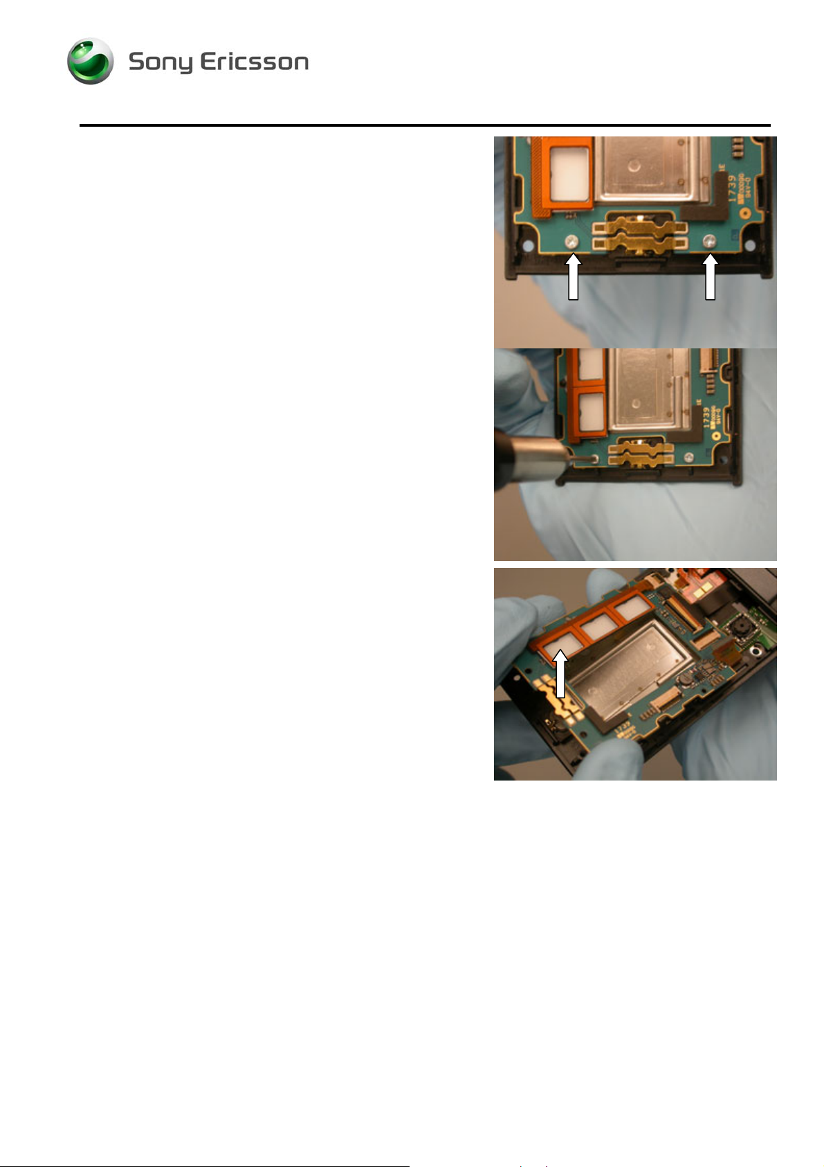
4.1.7 Lower PCB Installation
Connect the PCB and flex as shown.
Lay the board into place and press on the board so that the
two latches snap into place.
OTE: ENSURE THE COAX CABLE IS NOT UNDER THE PCB
N
Lay the foam gasket into place.
1208-3927 2
© Sony Ericsson Mobile Communications AB
72(79)
Page 73

Working Instruction, Mechanical
Connect the flex as shown.
Connect the coax cable and position the connection so that
it oriented as shown.
4.1.8 Vibrator Installation
Place the vibrator in its cavity.
OTE: DO NOT PRESS ON THE CONTACT FINGERS.
N
1208-3927 2
© Sony Ericsson Mobile Communications AB
73(79)
Page 74

Working Instruction, Mechanical
4.1.9 SIM/M2 Flex Installation
Connect the flex to the PCB as shown.
Place the vibrator cap over the vibrator.
N
OTE: THE VIBRATOR CAP SHOULD FIT OUTSIDE THE RUBBER
VIBRATOR GASKET
N
OTE: ENSURE THE VIBRATOR CAP IS ABLE TO SPRING OFF
THE VIBRATOR WHEN PRESSED ON
Position the volume key flex around the tab shown using
the round tipped tweezers.
1208-3927 2
© Sony Ericsson Mobile Communications AB
74(79)
Page 75

Working Instruction, Mechanical
Place the ESD cushion on the hinge flex as shown.
Push the edges of the cushion into the gap as shown.
1208-3927 2
© Sony Ericsson Mobile Communications AB
75(79)
Page 76

Working Instruction, Mechanical
4.1.10 Lower Back Cover Installation
Insert the tab at the key lock end of the lower back cover
under the edge of the lower front cover as shown.
Carefully lay the cover over the SIM/M2 flex and snap it into
place.
Snap the bottom half of the cover into place.
1208-3927 2
© Sony Ericsson Mobile Communications AB
76(79)
Page 77

Working Instruction, Mechanical
4.1.11 Lower Back Screw Installation
Insert the four screws in the locations shown. Tighten to 13
Ncm using a T5 bit.
4.1.12 Screw Cover Installation
Place the screw covers in the screw cavities.
N
OTE: DO NOT REUSE SCREW COVERS
1208-3927 2
© Sony Ericsson Mobile Communications AB
77(79)
Page 78

Working Instruction, Mechanical
4.1.13 Battery Installation
Insert the battery with the contacts aligned with the contact
pins.
Push the battery into place.
1208-3927 2
© Sony Ericsson Mobile Communications AB
78(79)
Page 79

Working Instruction, Mechanical
4.1.14 Battery Cover Installation
Insert the tabs of the battery cover into the slots in the lower
back cover.
Rotate the battery cover onto the phone and snap the
battery cover into place.
5 Revision History
Rev. Date Changes / Comments
1 February 26, 2008 Initial Release
2 April 14, 2008 Updated minor spelling and grammar errors
1208-3927 2
© Sony Ericsson Mobile Communications AB
79(79)
 Loading...