

Page 1

Working Instruction, Mechanical
Working Instruction, Mechanical
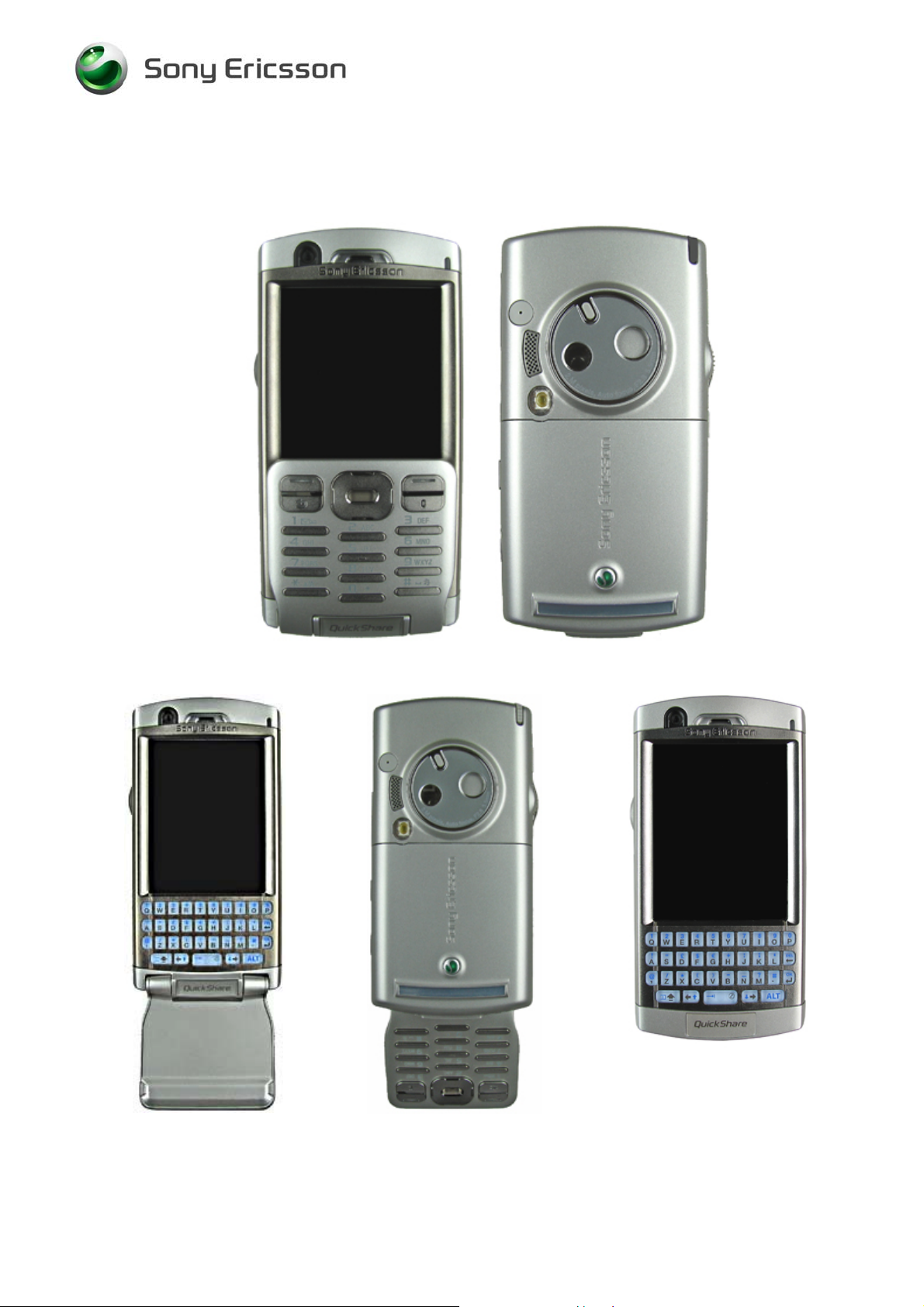
Applicable for P990i
CONTENTS
1 Introduction ..............................................................................3
1.1 Equipment.................................................................................4
1.2 General cautions......................................................................5
2 Disassembly .............................................................................6
2.1 Overview ...................................................................................6
2.1.1 Battery Lid asm & Battery......................................................7
2.1.2 Flip asm.................................................................................8
2.1.3 Bezel Top..............................................................................9
2.1.4 Cabinet Lower Sub asm......................................................10
2.1.5 Cabinet Upper Sub asm......................................................12
3 Replacements.........................................................................13
3.1 Battery Lid...............................................................................14
3.2 Flip...........................................................................................14
3.3 Bezel Top ................................................................................14
3.4 Cabinet Lower Sub.................................................................14
3.5 Cabinet Upper Sub.................................................................14
3.6 Ext Antenna Cap.....................................................................15
3.7 Stylus asm ..............................................................................16
3.8 Co-Branding Plate..................................................................17
3.9 Bezel Replacement asm ........................................................18
3.10 Camera Bezel asm..................................................................20
3.11 Memory Stick Cover...............................................................21
3.12 Dust Cover ..............................................................................22
3.13 System Connector..................................................................23
3.14 Flex Film, Camera Cover Switch...........................................24
3.15 Liquid Intrusion Indicator......................................................26
3.16 Antenna/Acoustic asm...........................................................27
3.17 Box Tape .................................................................................29
3.18 Heat, Conductive 9.4 x 1.5 mm..............................................30
3.19 Heat, Conductive 5.7 x 1.5 mm..............................................31
3.20 Flash Flex asm........................................................................32
3.21 Keyboard QWERTY................................................................33
3.22 LCD Gasket.............................................................................34
3/000 21-1/FEA 209 544/97 A
©
Sony Ericsson Mobile Communications AB
Approved according to FEA matrix doc. no.
Page 2

Working Instruction, Mechanical
3.23 Ear Speaker.............................................................................35
3.24 Vibrator....................................................................................36
3.25 Power Key...............................................................................37
3.26 LCD Frame asm......................................................................38
3.27 Shield Box VGA Camera........................................................41
3.28 Camera Module, VGA.............................................................43
3.29 VGA Support asm...................................................................44
3.30 Camera, 2M Pixel, Shielding Box Mpixel Camera ...............45
3.31 LCD..........................................................................................48
3.32 Isolation Tape.........................................................................50
3.33 Touch Panel asm + Frame.....................................................51
3.34 Label........................................................................................55
4 Reassembly ............................................................................56
4.1 Overview .................................................................................56
4.1.1 Cabinet Upper Sub asm......................................................57
4.1.2 Cabinet Lower Sub asm......................................................58
4.1.3 Bezel Top............................................................................59
4.1.4 Flip asm...............................................................................60
4.1.5 Battery & Battery Lid asm....................................................61
5 Revision history.....................................................................62
3/000 21-1/FEA 209 544/97 A
©
Sony Ericsson Mobile Communications AB
2(62)
Page 3
Working Instruction, Mechanical
1 Introduction
P990i
3/000 21-1/FEA 209 544/97 A
©
Sony Ericsson Mobile Communications AB
3(62)
Page 4
Working Instruction, Mechanical
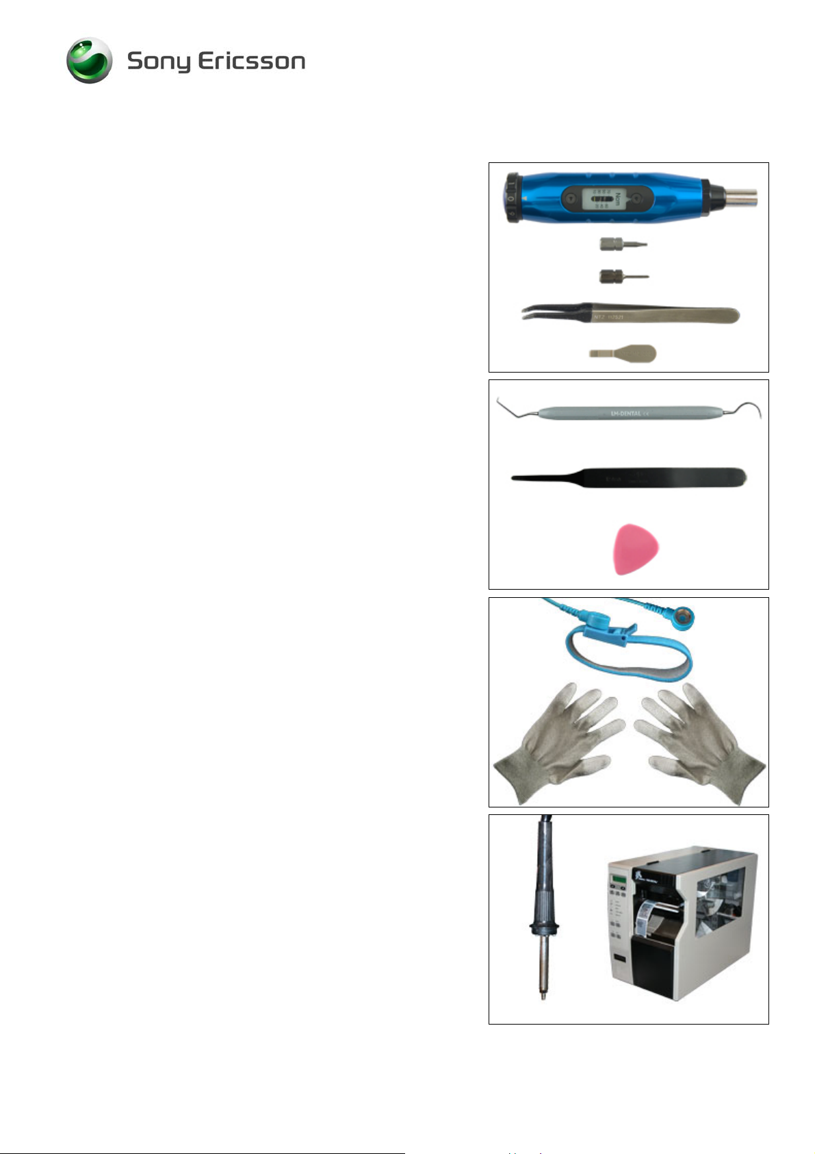
1.1 Equipment
SPECIAL TOOLS
• NTZ 112 459 Torque screwdriver (or equivalent)
• NTZ 112 288 Torx bit no. 6
• NTZ 112 1052 JCIS bit
• NTZ 112 521 Flex film assembly tool
• NTZ 112 302/2 Front opening tool
STANDARD TOOLS
• Dentist hook
• Blunt pair of tweezers
• Guitar pick
ESD EQUIPMENT
Protect the phone from ESD damages whenever it has
been opened by using:
• ESD-wristband
• ESD-gloves
LABEL EQUIPMENT
The following special equipment is required when replacing
or installing a new label:
• Hot air flow solder station
• Zebra printer connected to computer
3/000 21-1/FEA 209 544/97 A
©
Sony Ericsson Mobile Communications AB
4(62)
Page 5
Working Instruction, Mechanical
1.2 General cautions
The following cautions are considered to be generic for all phone models and will not be repeated in
the Disassembly, Replacements and Reassembly sections:
KEEP ALL CONTACT SURFACES CLEAN
•
BE CAREFUL WHEN USING TOOLS LIKE THE DENTIST HOOK, TWEEZERS, OPENING TOOLS, GUITAR PICK
•
ETC. TO AVOID SCRATCHES OR DAMAGES TO THE EXTERIOR AND INTERIOR PARTS OF THE PHONE
•
BE CAREFUL NOT TO DAMAGE ANY CONTACT SPRINGS
NEVER TOUCH THE DISPLAY GLASS
•
USE AIR BLOW EQUIPMENT TO KEEP THE DISPLAY MODULE DUST FREE
•
!
!
!
!
!
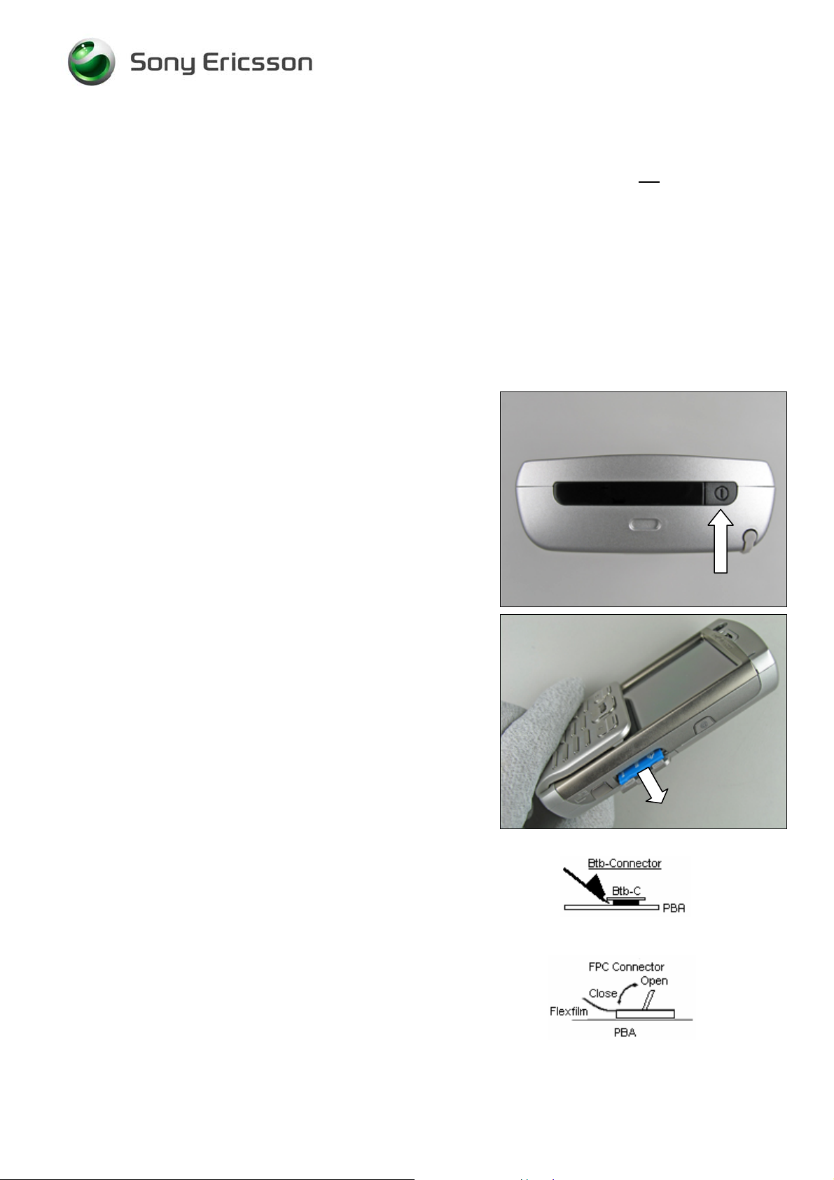
Press the On/Off button to turn off the phone.
Check that the memory stick has been removed.
How to open a board-to-board connector with the front
opening tool.
How to open and close a FPC connector (often done with a
dentist hook).
3/000 21-1/FEA 209 544/97 A
©
Sony Ericsson Mobile Communications AB
5(62)
Page 6
Working Instruction, Mechanical
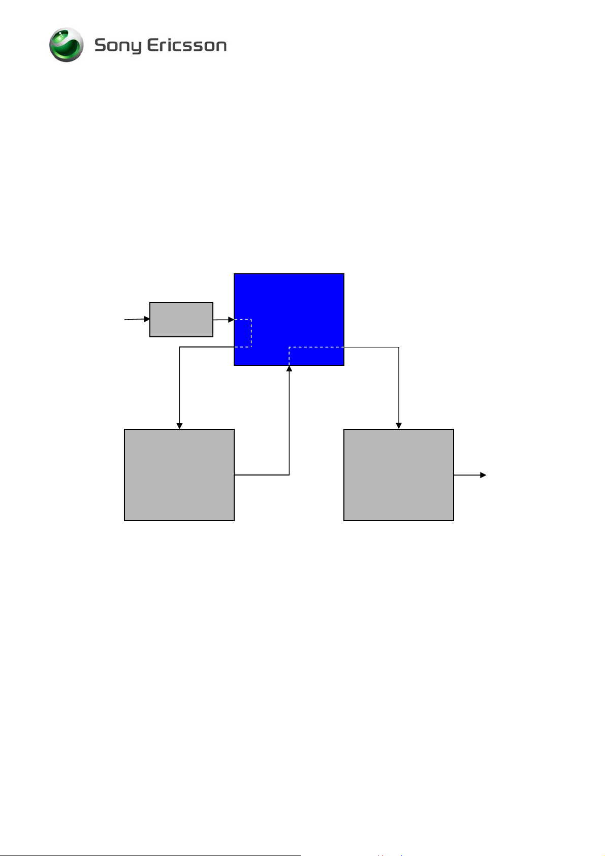
2 Disassembly
When you are going to replace a part being listed in Replacements, the instruction of that section
usually begins by directing you to this Disassembly section with a specification of the instructions you
have to carry out in order to disassemble the phone as far as needed before returning to
Replacements for the actual replacement.
REPLACEMENTS
Start
Contents
page
DISASSEMBLY
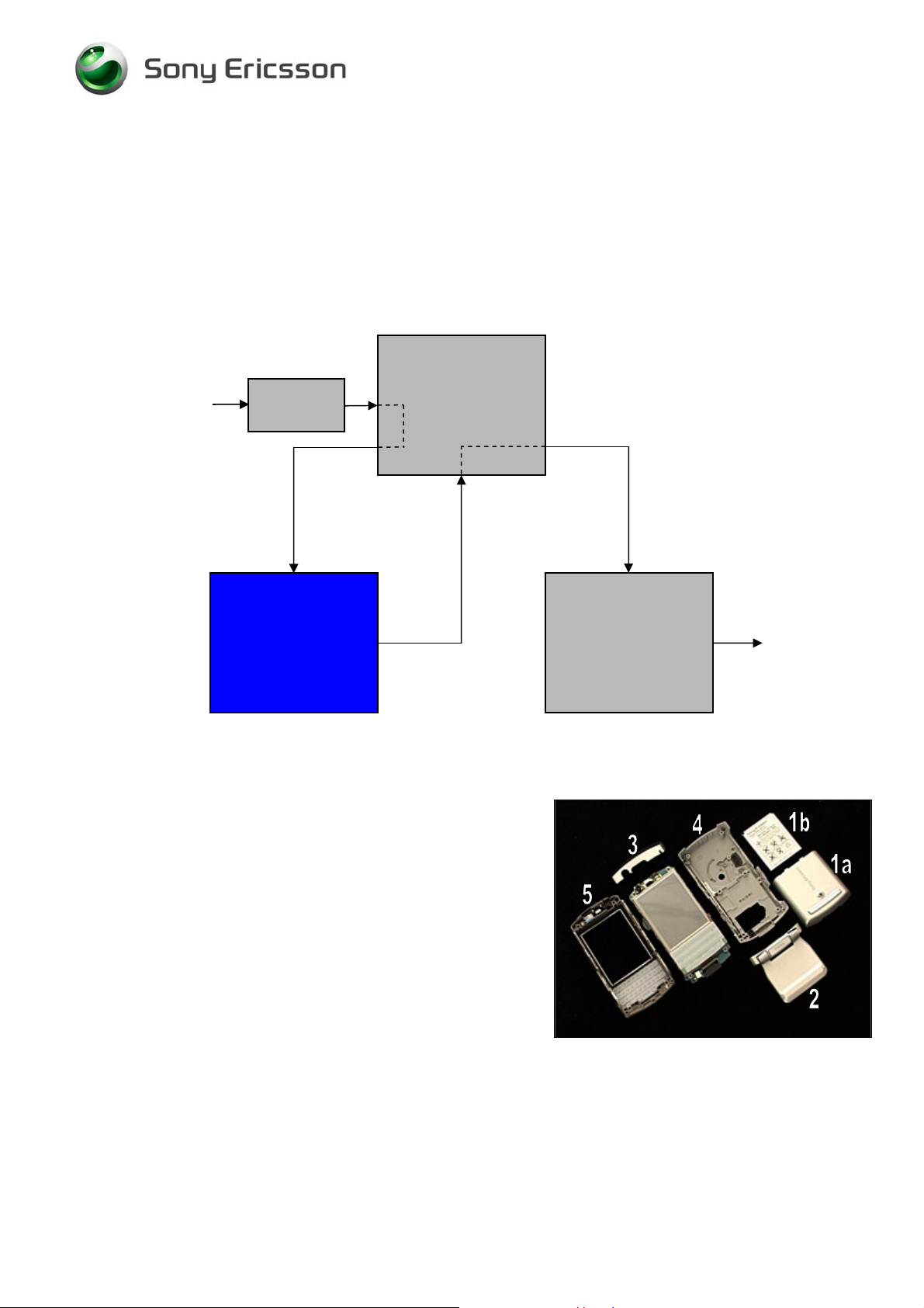
2.1 Overview
The disassembly is done in the following sequence:
1. Battery Lid (a) & Battery (b)
2. Flip
3. Bezel Top
4. Cabinet Lower Sub
5. Cabinet Upper Sub
REASSEMBLY
Done
3/000 21-1/FEA 209 544/97 A
©
Sony Ericsson Mobile Communications AB
6(62)
Page 7
Working Instruction, Mechanical
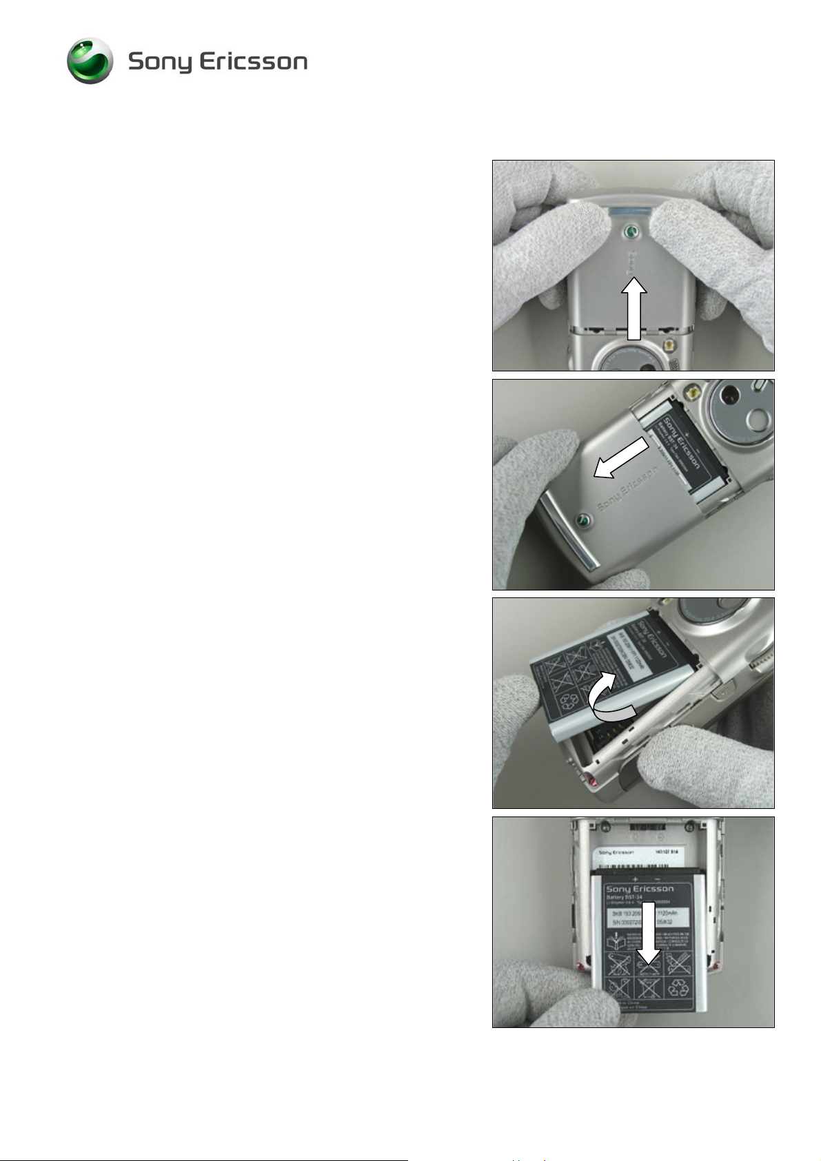
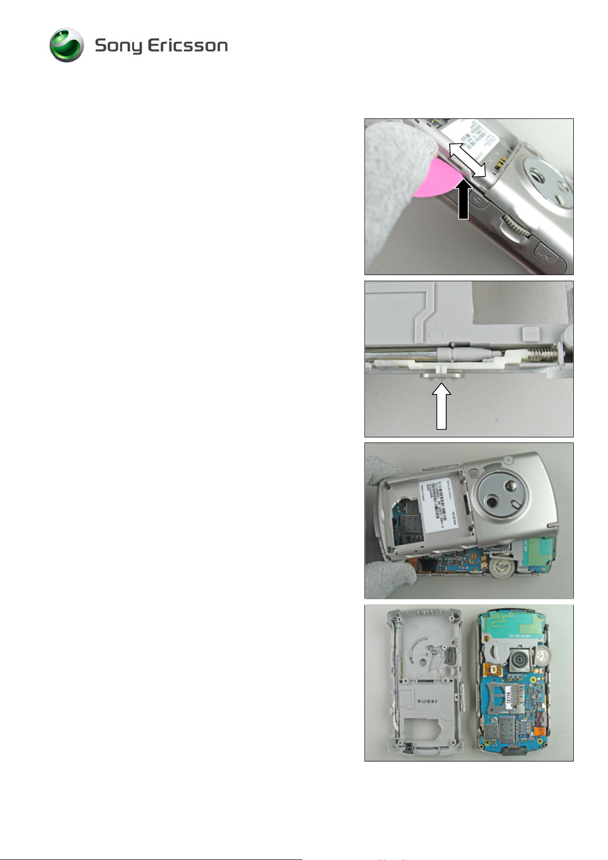
2.1.1 Battery Lid asm & Battery
Press the battery lid backwards until you get a gap by using
your thumbs.
Slide down the battery lid from its mounted position towards
the bottom of the phone and remove it.
Start to remove the battery from the phone with your fingers
or the front opening tool.
Lift up the battery to release it.
If not released, turning the phone around at the same time
will make it become released.
Remove the battery from the phone with your fingers.
3/000 21-1/FEA 209 544/97 A
©
Sony Ericsson Mobile Communications AB
7(62)
Page 8
Working Instruction, Mechanical
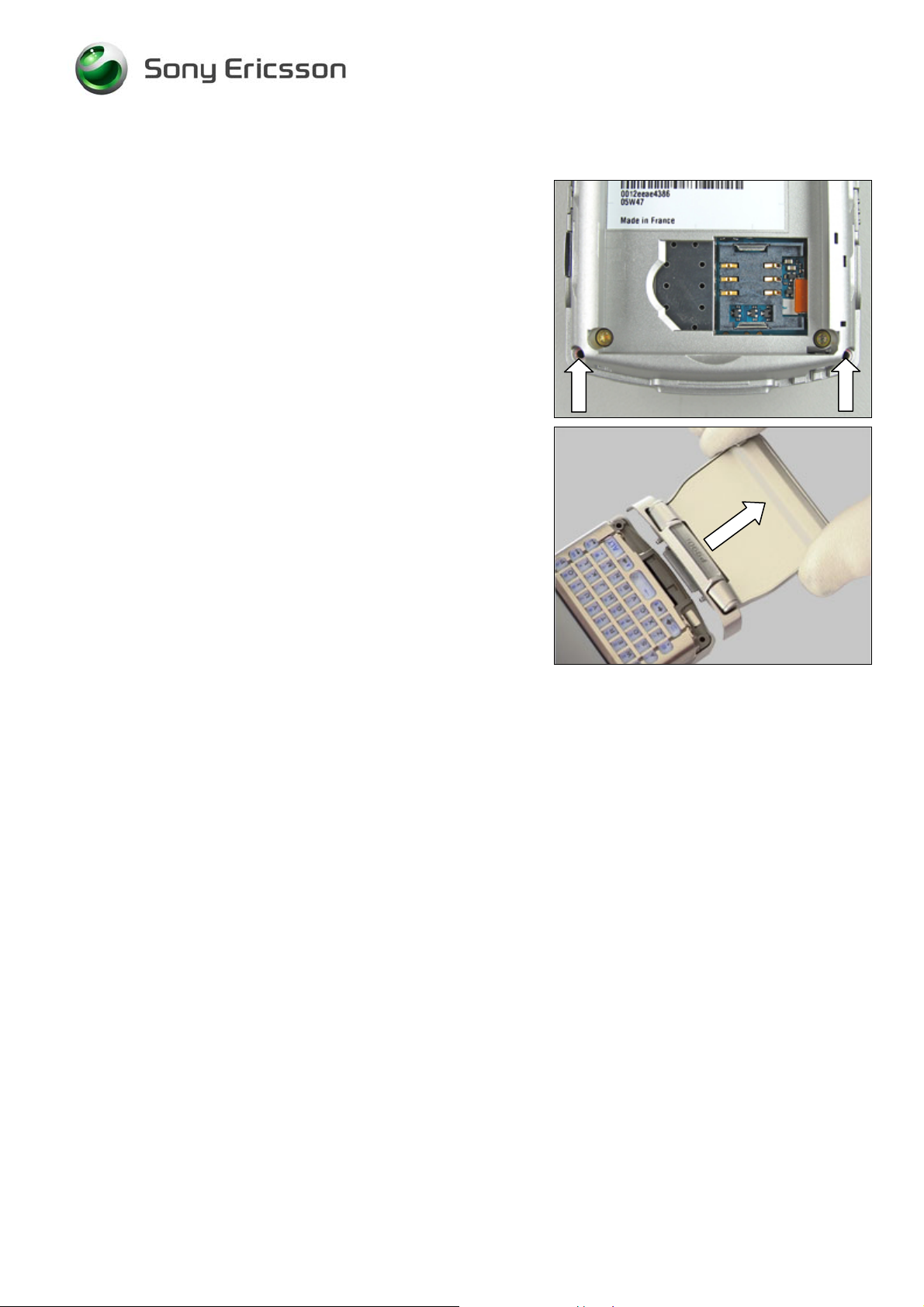
2.1.2 Flip asm
Use the JCIS bit to remove the two screws from the lower
cabinet sub.
EMOVED SCREWS CANNOT BE REUSED AND MUST BE
R
SCRAPPED
!
Pull the flip straight backwards to remove it.
3/000 21-1/FEA 209 544/97 A
©
Sony Ericsson Mobile Communications AB
8(62)
Page 9
Working Instruction, Mechanical
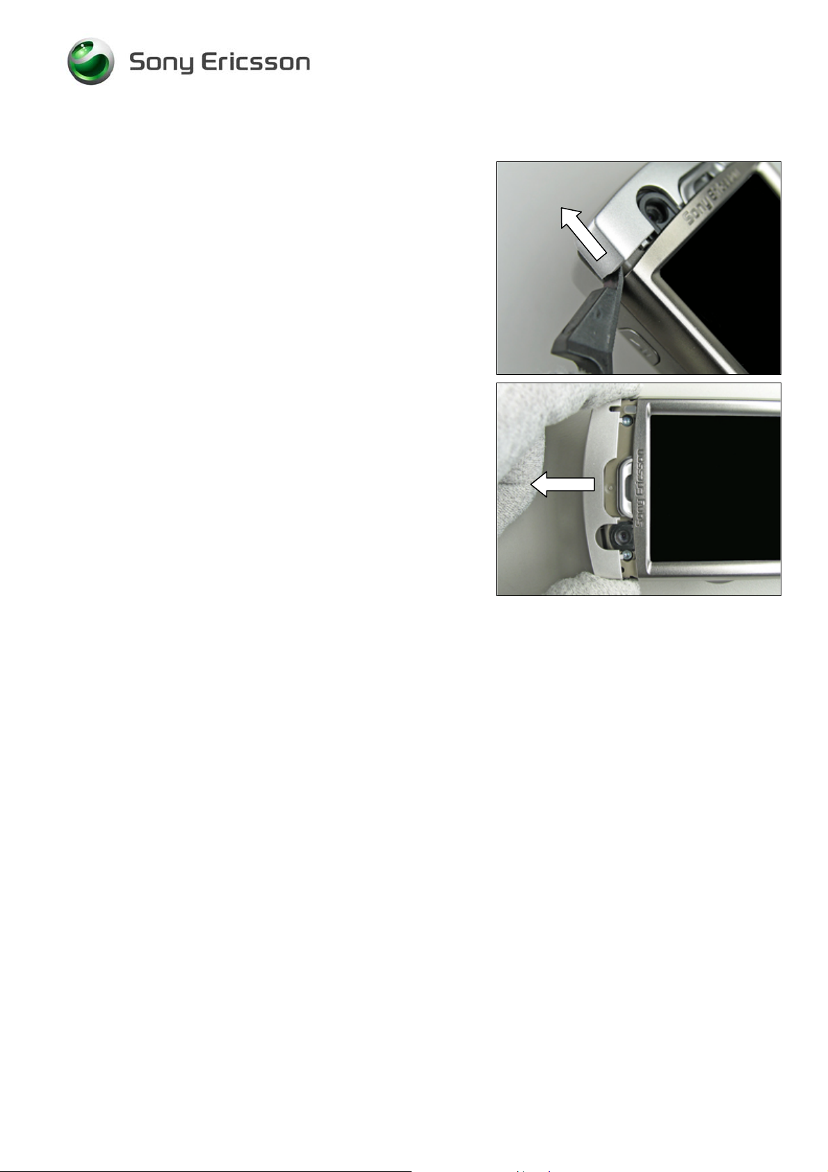
2.1.3 Bezel Top
Press the front opening tool in the joint between the bezel
top and the cabinet upper sub until it becomes loose.
If necessary, do the same thing on the opposite side.
Pull the bezel top straight backwards and remove it by
hand.
3/000 21-1/FEA 209 544/97 A
©
Sony Ericsson Mobile Communications AB
9(62)
Page 10
Working Instruction, Mechanical
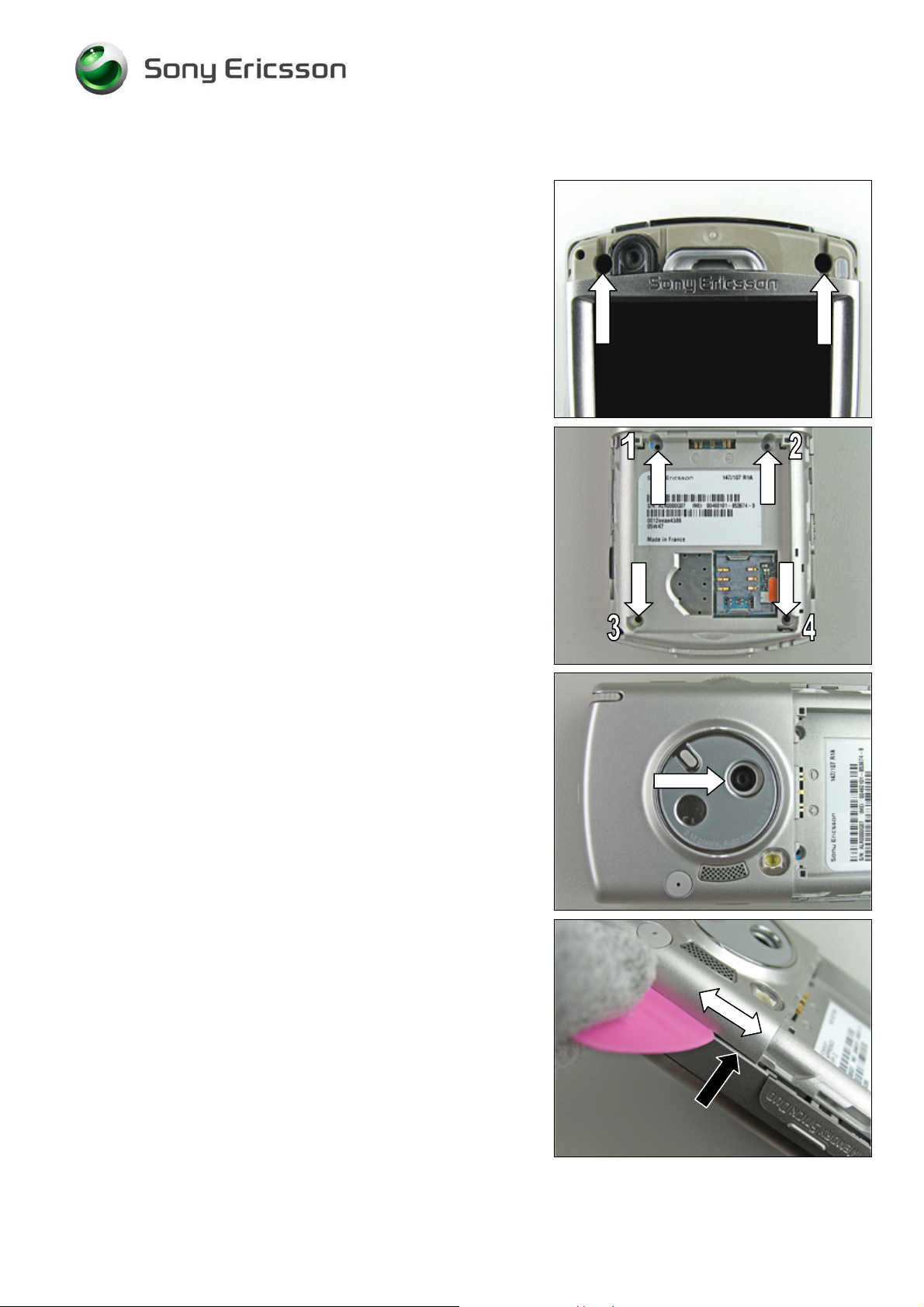
2.1.4 Cabinet Lower Sub asm
Remove the two top screws by using torx bit no. 6.
EMOVED SCREWS CAN BE REUSED IF THEY ARE NOT
R
DAMAGED
Remove the four inside screws by using torx bit no. 6.
EMOVED SCREWS 1 & 2 CANNOT BE REUSED AND MUST BE
R
SCRAPPED
R
EMOVED SCREWS 3 & 4 CAN BE REUSED IF THEY ARE NOT
DAMAGED
!
!
!
T
HE CAMERA LID MUST BE OPEN WHEN THE CABINET LOWER
SUB IS REMOVED FROM THE PHONE
.
Open the camera lid with your fingers.
Gently but firmly move the guitar pick along the gap
(starting where the gap is widest) both ways until the
cabinet lower sub is loose on this side.
The snap hook to be released is located at the position of
the black arrow.
3/000 21-1/FEA 209 544/97 A
©
Sony Ericsson Mobile Communications AB
10(62)
Page 11
Working Instruction, Mechanical
Cabinet Lower Sub asm continued
Continue to do the same thing on the opposite side.
Sometimes during the removal of the cabinet lower sub the
key lock button may fall out.
Remove the cabinet lower sub.
Cabinet lower sub removed.
3/000 21-1/FEA 209 544/97 A
©
Sony Ericsson Mobile Communications AB
11(62)
Page 12
Working Instruction, Mechanical
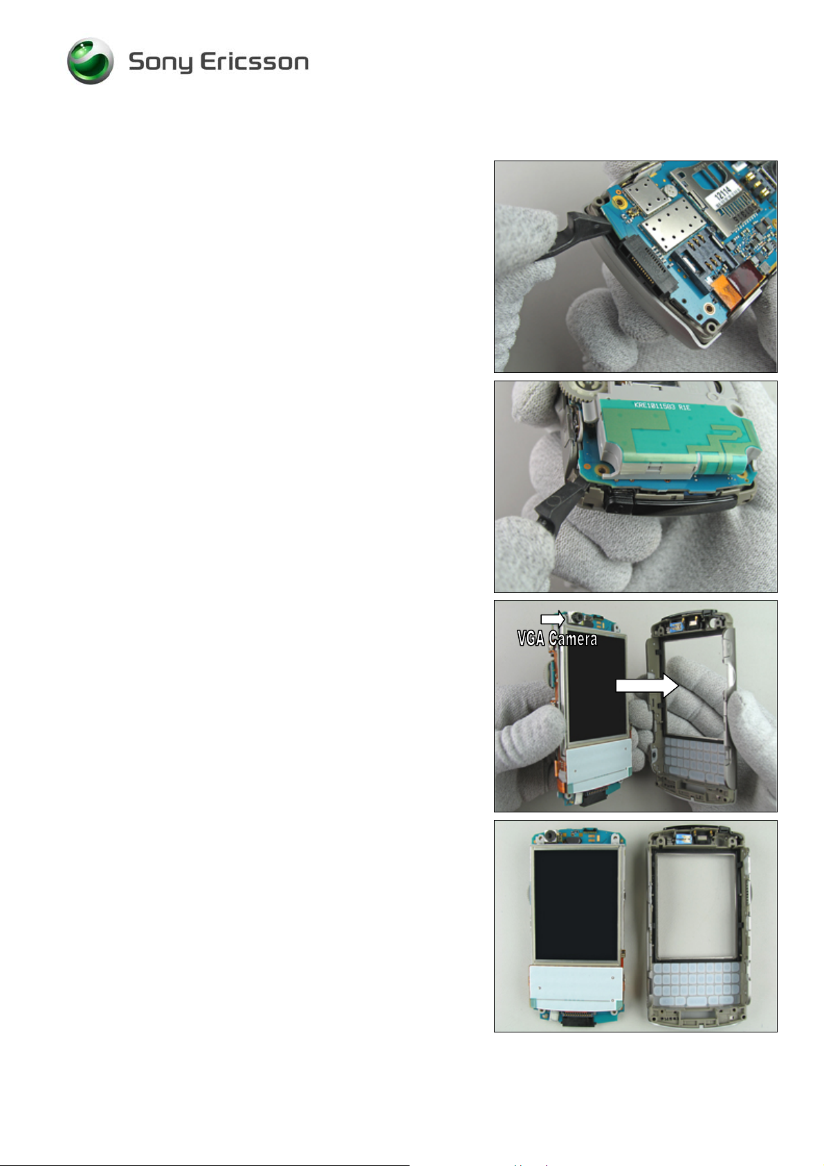
2.1.5 Cabinet Upper Sub asm
Gently bend with the front opening tool under the main PBA
like the picture shows until it starts to become loose at the
bottom of the phone.
Continue to bend under the main PBA like the picture
shows until it is completely free from the front.
B
E CAREFUL WITH THE VGA CAMERA WHEN THE PBA/LCD
SEPARATES FROM THE FRONT
!
Sometimes the keyboard will fall out when the front is
removed.
If necessary, wiggle the front slightly side to side while lifting
the PBA/LCD away from the front.
Cabinet upper sub removed
3/000 21-1/FEA 209 544/97 A
©
Sony Ericsson Mobile Communications AB
12(62)
Page 13
Working Instruction, Mechanical
3 Replacements
Search for the part to be replaced on the Contents page and go to that instruction to be found in this
Replacements section.
The instruction usually begins by directing you to the Disassembly section with a specification of the
instructions you have to carry out in order to disassemble the phone as far as needed before the
actual replacement.
Go back to this Replacements section and carry out the instruction.
The instruction usually ends by directing you to the Reassembly section with a specification of the
instructions you have to carry out in order to reassemble the phone.
REPLACEMENTS
Start
Contents
page
DISASSEMBLY REASSEMBLY
Done
3/000 21-1/FEA 209 544/97 A
©
Sony Ericsson Mobile Communications AB
13(62)
Page 14

Working Instruction, Mechanical
3.1 Battery Lid
Follow the 2.1.1 Disassembly instructions!
Prepare the new battery lid.
Follow the 4.1.5 Reassembly instructions!
3.2 Flip
Follow the 2.1.1 - 2.1.2 Disassembly instructions!
Prepare the new flip.
Follow the 4.1.4 - 4.1.5 Reassembly instructions!
3.3 Bezel Top
Follow the 2.1.3 Disassembly instructions!
Prepare the new bezel top.
Follow the 4.1.3 Reassembly instructions!
3.4 Cabinet Lower Sub
Follow the 2.1.1- 2.1.4 Disassembly instructions!
Prepare the new cabinet lower sub.
Follow the 4.1.2 – 4.1.5 Reassembly instructions!
3.5 Cabinet Upper Sub
Follow the 2.1.1 – 2.1.5 Disassembly instructions!
Prepare the new cabinet upper sub.
Follow the 4.1.1 – 4.1.5 Reassembly instructions!
3/000 21-1/FEA 209 544/97 A
©
Sony Ericsson Mobile Communications AB
14(62)
Page 15
Working Instruction, Mechanical
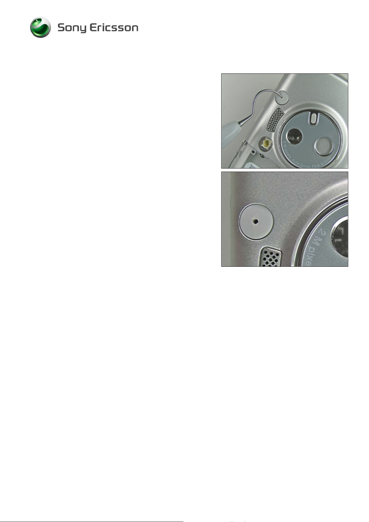
3.6 Ext Antenna Cap
REMOVAL
Remove the external antenna cap with a dentist hook.
INSTALLATION
Insert a new external antenna cap with your fingers.
3/000 21-1/FEA 209 544/97 A
©
Sony Ericsson Mobile Communications AB
15(62)
Page 16
Working Instruction, Mechanical
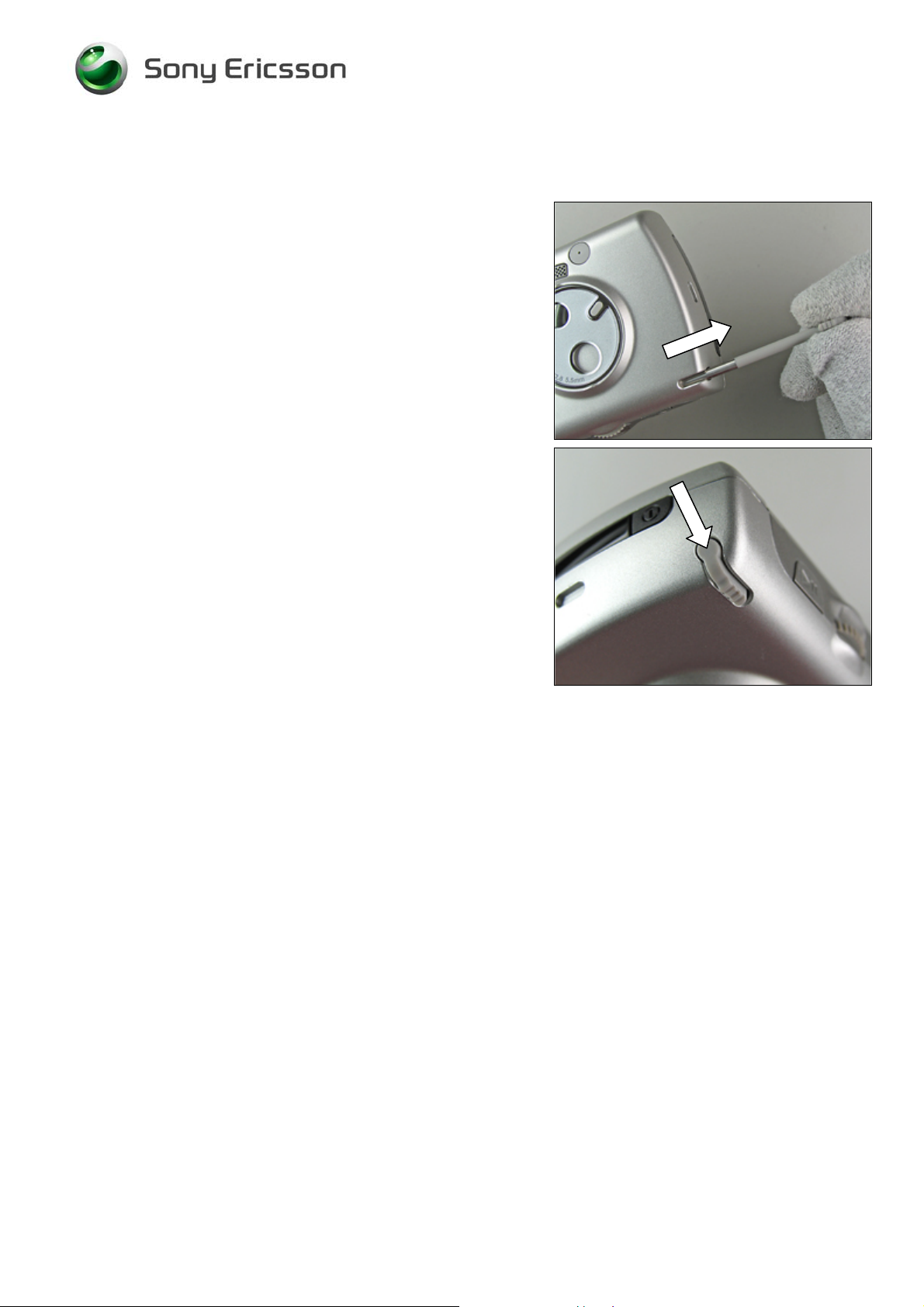
3.7 Stylus asm
REMOVAL
Remove the stylus with your fingers.
INSTALLATION
Insert the stylus with your fingers.
3/000 21-1/FEA 209 544/97 A
©
Sony Ericsson Mobile Communications AB
16(62)
Page 17
Working Instruction, Mechanical
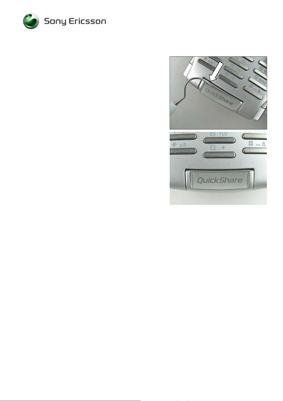
3.8 Co-Branding Plate
REMOVAL
Gently remove the co-branding plate with a dentist hook.
INSTALLATION
Attach the co-branding plate with the tweezers or by hand.
Keep the pressure on for a few seconds to secure a good
attachment.
3/000 21-1/FEA 209 544/97 A
©
Sony Ericsson Mobile Communications AB
17(62)
Page 18
Working Instruction, Mechanical
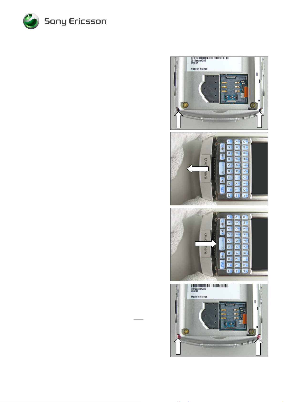
3.9 Bezel Replacement asm
REMOVAL
Follow the 2.1.1 Disassembly instructions!
T
HIS INSTRUCTION DESCRIBES HOW TO REMOVE AND INSTALL
A BEZEL REPLACEMENT ON A PHONE WHERE THE FLIP HAS
BEEN REPLACED BY A BEZEL
Use the JCIS bit to remove the two screws from the cabinet
lower sub.
EMOVED SCREWS CANNOT BE REUSED AND MUST BE
R
SCRAPPED
!
.
Pull the bezel replacement straight backwards to remove it.
INSTALLATION
Gently place the bezel replacement over the cabinet upper
sub.
Apply 15 Ncm ± 2 Ncm of torque for the two new screws
by using the JCIS bit!
3/000 21-1/FEA 209 544/97 A
©
Sony Ericsson Mobile Communications AB
18(62)
Page 19
Working Instruction, Mechanical
Bezel Replacement asm continued
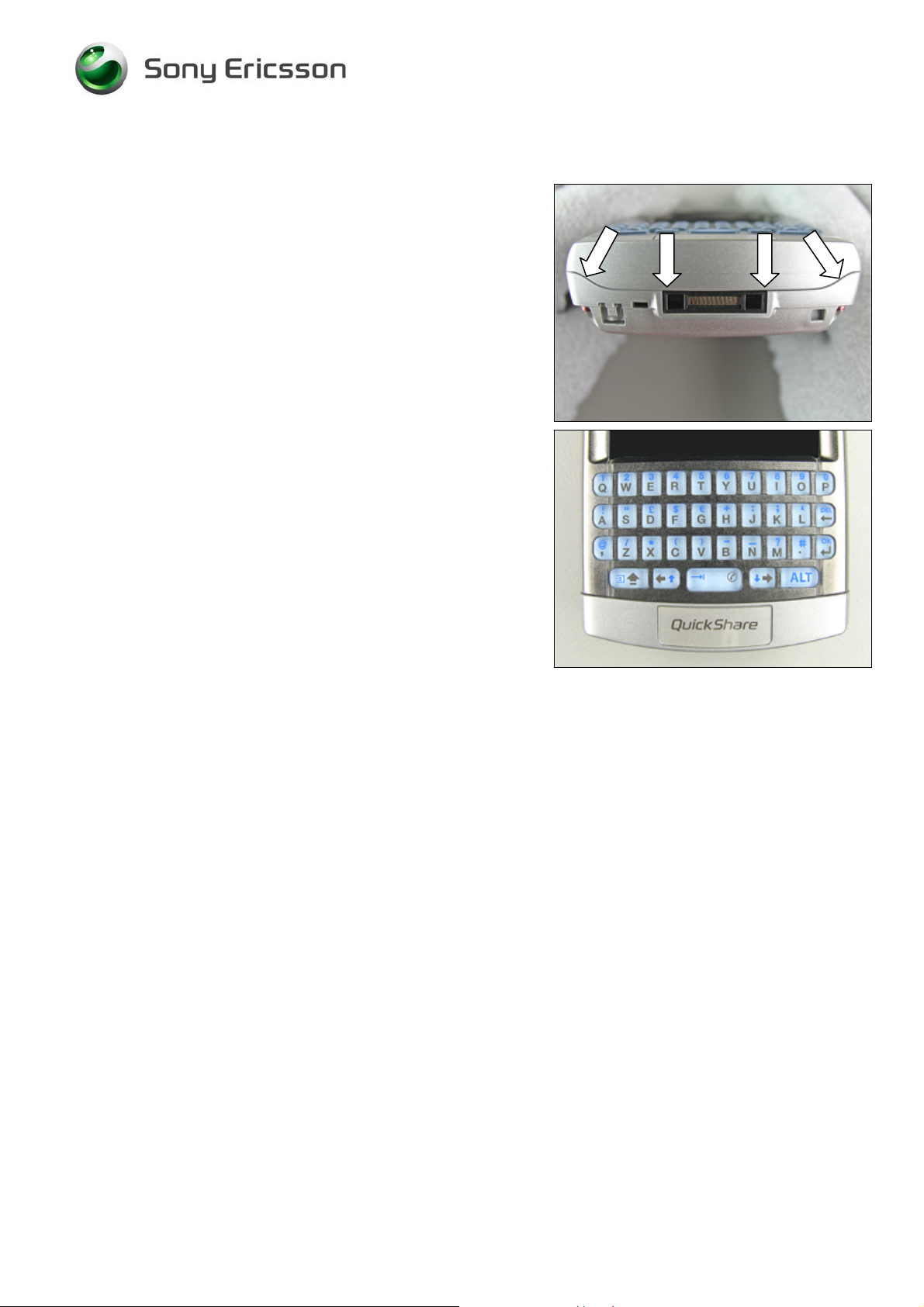
Make sure that there are no gaps around the bezel
replacement.
If there still is a gap recheck your torque setting and
retighten the screws.
Correctly mounted bezel replacement.
Follow the 4.1.5 Reassembly instructions!
3/000 21-1/FEA 209 544/97 A
©
Sony Ericsson Mobile Communications AB
19(62)
Page 20

Working Instruction, Mechanical
3.10 Camera Bezel asm
REMOVAL
Follow the 2.1.3 Disassembly instructions!
Use the tweezers to bend under the camera bezel until it
becomes loose.
Remove the camera bezel with the tweezers.
INSTALLATION
Install a new camera bezel with the tweezers.
Press on the edges to make a secure fit.
Correctly mounted camera bezel.
Follow the 4.1.3 Reassembly instructions!
3/000 21-1/FEA 209 544/97 A
©
Sony Ericsson Mobile Communications AB
20(62)
Page 21

Working Instruction, Mechanical
3.11 Memory Stick Cover
REMOVAL
Follow the 2.1.1 – 2.1.4 Disassembly instructions!
Before the actual removal – turn the memory stick cover 90˚
left or right, and then remove it with your fingers.
INSTALLATION
First turn the memory stick cover 90˚ left or right, then
attach the new memory stick cover over the fastening pin.
Follow the 4.1.2 - 4.1.5 Reassembly instructions!
3/000 21-1/FEA 209 544/97 A
©
Sony Ericsson Mobile Communications AB
21(62)
Page 22

Working Instruction, Mechanical
3.12 Dust Cover
REMOVAL
Follow the 2.1.1 – 2.1.4 Disassembly instructions!
Remove the dust cover with the tweezers.
INSTALLATION
Attach a new dust cover with the tweezers
Follow the 4.1.2 - 4.1.5 Reassembly instructions!
3/000 21-1/FEA 209 544/97 A
©
Sony Ericsson Mobile Communications AB
22(62)
Page 23

Working Instruction, Mechanical
3.13 System Connector
REMOVAL
Follow the 2.1.1 – 2.1.4 Disassembly instructions!
Remove the system connector by hand.
INSTALLATION
Mount a new system connector with your fingers.
Press the system connector firmly to the bottom of the PBA
as shown in picture.
Follow the 4.1.2 - 4.1.5 Reassembly instructions!
3/000 21-1/FEA 209 544/97 A
©
Sony Ericsson Mobile Communications AB
23(62)
Page 24

Working Instruction, Mechanical
3.14 Flex Film, Camera Cover Switch
REMOVAL
Follow the 2.1.1 – 2.1.4 Disassembly instructions!
Gently open the FPC connector with the dentist hook.
Pull the flex film, camera cover switch straight backwards
out of the FPC connector with the flex film assembly tool.
Use the dentist hook to make the flex film become loose
from the speaker box.
Remove the flex film with the flex film assembly tool.
3/000 21-1/FEA 209 544/97 A
©
Sony Ericsson Mobile Communications AB
24(62)
Page 25

Working Instruction, Mechanical
Flex Film, Camera Cover Switch continued
INSTALLATION
Start the installation of a new flex film, camera cover switch
with the flex film assembly tool.
Insert the flex film into the FPC connector with the flex film
assembly tool.
Make sure that the flex film is pushed all the way into the
bottom of the connector.
Close the FPC connector with the dentist hook.
Follow the 4.1.2 - 4.1.5 Reassembly instructions!
3/000 21-1/FEA 209 544/97 A
©
Sony Ericsson Mobile Communications AB
25(62)
Page 26

Working Instruction, Mechanical
3.15 Liquid Intrusion Indicator
REMOVAL
Follow the 2.1.1 – 2.1.4 Disassembly instructions!
Follow the 3.14 Removal instructions!
Remove the two board-to-board connectors with the front
opening tool.
Remove the first liquid intrusion indicator with the dentist
hook.
Remove the second liquid intrusion indicator with a dentist
hook.
INSTALLATION
Attach two new liquid intrusion indicators with the dentist
hook.
Then connect the two board-to-board connectors, starting
with no. 1.
Follow the 3.14 Installation instructions!
Follow the 4.1.2 - 4.1.5 Reassembly instructions!
3/000 21-1/FEA 209 544/97 A
©
Sony Ericsson Mobile Communications AB
26(62)
Page 27

Working Instruction, Mechanical
3.16 Antenna/Acoustic asm
REMOVAL
Follow the 2.1.1 – 2.1.4 Disassembly instructions!
Follow the 3.14 Removal instructions!
Gently bend under the flash LED with a dentist hook until it
becomes loose.
Use the front opening tool to bend under the antenna/
acoustic until it becomes loose.
Lift and remove the antenna/acoustic from the main PBA by
hand.
INSTALLATION
Install the antenna/acoustic onto the main PBA.
3/000 21-1/FEA 209 544/97 A
©
Sony Ericsson Mobile Communications AB
27(62)
Page 28

Working Instruction, Mechanical
Antenna/Acoustic asm continued
Gently fold and attach the flash LED to the antenna/
acoustic.
Make sure it is mounted correctly on the two guide pins.
Follow the 3.14 Installation instructions!
Follow the 4.1.2 - 4.1.5 Reassembly instructions!
3/000 21-1/FEA 209 544/97 A
©
Sony Ericsson Mobile Communications AB
28(62)
Page 29

Working Instruction, Mechanical
3.17 Box Tape
REMOVAL
Follow the 2.1.1 – 2.1.4 Disassembly instructions!
Follow the 3.14 & 3.16 Removal instructions!
Remove the box tape with a dentist hook.
INSTALLATION
Attach a new box tape with the tweezers.
Follow the 3.16 & 3.14 Installation instructions!
Follow the 4.1.2 - 4.1.5 Reassembly instructions!
3/000 21-1/FEA 209 544/97 A
©
Sony Ericsson Mobile Communications AB
29(62)
Page 30

Working Instruction, Mechanical
3.18 Heat, Conductive 9.4 x 1.5 mm
REMOVAL
Follow the 2.1.1 – 2.1.4 Disassembly instructions!
Follow the 3.14 & 3.16 Removal instructions!
Remove the heat conductive with the dentist hook.
INSTALLATION
Attach a new heat conductive with the tweezers.
Follow the 3.16 & 3.14 Installation instructions!
Follow the 4.1.2 - 4.1.5 Reassembly instructions!
3/000 21-1/FEA 209 544/97 A
©
Sony Ericsson Mobile Communications AB
30(62)
Page 31

Working Instruction, Mechanical
3.19 Heat, Conductive 5.7 x 1.5 mm
REMOVAL
Follow the 2.1.1 – 2.1.4 Disassembly instructions!
Follow the 3.14 & 3.16 Removal instructions!
Remove the heat conductive with the dentist hook.
INSTALLATION
Attach a new heat conductive with the tweezers.
Follow the 3.16 & 3.14 Installation instructions!
Follow the 4.1.2 - 4.1.5 Reassembly instructions!
3/000 21-1/FEA 209 544/97 A
©
Sony Ericsson Mobile Communications AB
31(62)
Page 32

Working Instruction, Mechanical
3.20 Flash Flex asm
REMOVAL
Follow the 2.1.1 – 2.1.4 Disassembly instructions!
Follow the 3.14 & 3.16 Removal instructions!
Use the front opening tool to disconnect the board-to-board
connector from the main PBA.
Remove the flash flex by hand.
INSTALLATION
Connect the new flash flex to the board-to-board connector.
Use your finger to gently press on the board-to-board
connector to make a secure connection.
Follow the 3.16 & 3.14 Installation instructions!
Follow the 4.1.2 - 4.1.5 Reassembly instructions!
3/000 21-1/FEA 209 544/97 A
©
Sony Ericsson Mobile Communications AB
32(62)
Page 33

Working Instruction, Mechanical
3.21 Keyboard QWERTY
REMOVAL
Follow the 2.1.1 – 2.1.5 Disassembly instructions!
Remove the keyboard QWERTY with the tweezers or by
hand.
INSTALLATION
Put a new keyboard QWERTY in its proper position by
hand.
Follow the 4.1.1 - 4.1.5 Reassembly instructions!
3/000 21-1/FEA 209 544/97 A
©
Sony Ericsson Mobile Communications AB
33(62)
Page 34

Working Instruction, Mechanical
3.22 LCD Gasket
REMOVAL
Follow the 2.1.1 – 2.1.5 Disassembly instructions!
Remove the LCD gasket with the tweezers or by hand.
INSTALLATION
Attach a new LCD gasket by hand.
Follow the 4.1.1 - 4.1.5 Reassembly instructions!
3/000 21-1/FEA 209 544/97 A
©
Sony Ericsson Mobile Communications AB
34(62)
Page 35

Working Instruction, Mechanical
3.23 Ear Speaker
REMOVAL
Follow the 2.1.1 – 2.1.5 Disassembly instructions!
Start to bend up the ear speaker with the tweezers.
Continue to lift up the ear speaker and remove it with the
tweezers.
INSTALLATION
D
O NOT TOUCH OR BEND THE CONTACT SPRINGS
Press gently on each side of the new ear speaker to the
bottom of the cavity with the tweezers.
Check that the contact springs are in good condition and
that they are not deformed.
Follow the 4.1.1 - 4.1.5 Reassembly instructions!
!
3/000 21-1/FEA 209 544/97 A
©
Sony Ericsson Mobile Communications AB
35(62)
Page 36

Working Instruction, Mechanical
3.24 Vibrator
REMOVAL
Follow the 2.1.1 – 2.1.5 Disassembly instructions!
O NOT TOUCH THE VIBRATOR CONTACT SPRINGS OR DAMAGE
D
THE FLYWHEEL
Lift the vibrator straight up with the tweezers to remove it.
!
INSTALLATION
Press the new vibrator gently to the bottom of the cavity
with the tweezers.
Check that the contact springs are in good condition and
that they are not deformed.
Follow the 4.1.1 - 4.1.5 Reassembly instructions!
3/000 21-1/FEA 209 544/97 A
©
Sony Ericsson Mobile Communications AB
36(62)
Page 37

Working Instruction, Mechanical
3.25 Power Key
REMOVAL
Follow the 2.1.1 – 2.1.5 Disassembly instructions!
Bend gently under the power key with the tweezers until it
becomes loose.
Remove the power key with the tweezers or your fingers.
INSTALLATION
Insert a new power key into its proper position with the
tweezers.
Follow the 4.1.1 - 4.1.5 Reassembly instructions!
3/000 21-1/FEA 209 544/97 A
©
Sony Ericsson Mobile Communications AB
37(62)
Page 38

Working Instruction, Mechanical
3.26 LCD Frame asm
REMOVAL
Follow the 2.1.1 – 2.1.5 Disassembly instructions!
Use the front opening tool to disconnect the two board-toboard connectors from the main PBA (starting like the
picture shows).
These four hooks must be released before you can remove
the LCD frame.
Insert the front opening tool under the main PBA and gently
bend until you get a gap.
Continue until the main PBA is completely free from the
LCD frame.
Continue to do the same on the opposite side, if necessary.
3/000 21-1/FEA 209 544/97 A
©
Sony Ericsson Mobile Communications AB
38(62)
Page 39

Working Instruction, Mechanical
LCD Frame asm continued
Remove the main PBA from the LCD frame.
LCD frame removed from main PBA.
INSTALLATION
Place the main PBA and the LCD frame in your hands like
this.
Gently start to mate the LCD frame over the main PBA.
Turn the main PBA to the left into the LCD frame.
3/000 21-1/FEA 209 544/97 A
©
Sony Ericsson Mobile Communications AB
39(62)
Page 40

Working Instruction, Mechanical
LCD Frame asm continued
Place the LCD frame over the main PBA and snap them
together.
Make sure that the main PBA is in the right position, and
properly latched by the four hooks (two on each side of the
frame).
Gently fold the two flex films to the left (1 and 2).
Connect the two flex film board to board connectors with
your fingers starting with no. 1.
Follow the 4.1.1 - 4.1.5 Reassembly instructions!
3/000 21-1/FEA 209 544/97 A
©
Sony Ericsson Mobile Communications AB
40(62)
Page 41

Working Instruction, Mechanical
3.27 Shield Box VGA Camera
REMOVAL
Follow the 2.1.1 – 2.1.5 Disassembly instructions!
Follow the 3.26 Removal instructions!
Gently release the first hook with a dentist hook.
Release the second one on the opposite side.
Remove the shield box VGA camera with the tweezers.
INSTALLATION
Place the new shield box VGA camera over the camera
with the tweezers.
3/000 21-1/FEA 209 544/97 A
©
Sony Ericsson Mobile Communications AB
41(62)
Page 42

Working Instruction, Mechanical
Shield Box VGA Camera continued
Continue to snap the hooks onto each side of the shield
box.
Make sure that the shield box VGA camera is in the right
position and properly latched by the two hooks (one on
each side of the shield box).
Follow the 3.26 Installation instructions!
Follow the 4.1.1 - 4.1.5 Reassembly instructions!
3/000 21-1/FEA 209 544/97 A
©
Sony Ericsson Mobile Communications AB
42(62)
Page 43

Working Instruction, Mechanical
3.28 Camera Module, VGA
REMOVAL
Follow the 2.1.1 – 2.1.5 Disassembly instructions!
Follow the 3.26 & 3.27 Removal instructions!
Use the front opening tool to disconnect the camera
module, VGA’s board-to-board connector from the main
PBA.
Remove the camera module, VGA with the tweezers.
INSTALLATION
Install a new camera module, VGA.
Use your finger when connecting the board-to-board
connector to the main PBA.
Correctly installed camera mod u le, VGA.
Follow the 3.27 & 3.26 Installation instructions!
Follow the 4.1.1 - 4.1.5 Reassembly instructions!
3/000 21-1/FEA 209 544/97 A
©
Sony Ericsson Mobile Communications AB
43(62)
Page 44

Working Instruction, Mechanical
3.29 VGA Support asm
REMOVAL
Follow the 2.1.1 – 2.1.5 Disassembly instructions!
Follow the 3.26 & 3.27 Removal instructions!
Remove the VGA support with the tweezers.
INSTALLATION
Install a new VGA support by hand.
VGA support together with camera module,VGA.
Follow the 3.27 & 3.26 Installation instructions!
Follow the 4.1.1 - 4.1.5 Reassembly instructions!
3/000 21-1/FEA 209 544/97 A
©
Sony Ericsson Mobile Communications AB
44(62)
Page 45

Working Instruction, Mechanical
3.30 Camera, 2M Pixel, Shielding Box Mpixel Camera
REMOVAL
Follow the 2.1.1 – 2.1.5 Disassembly instructions!
Follow the 3.26 Removal instructions!
Start by removing the shielding box with your fingers.
Use the front opening tool to disconnect the camera, 2M
pixel’s board-to-board connector from the main PBA.
Gently put a guitar pick between the camera, 2M pixel and
the battery connector just enough to unsnap the two hooks
that holds the camera box in place on this side.
N
EVER TOUCH THE CAMERA LENS
!
Close up picture on the two hooks which secure the camera
box against the antenna/acoustic box.
3/000 21-1/FEA 209 544/97 A
©
Sony Ericsson Mobile Communications AB
45(62)
Page 46

Working Instruction, Mechanical
Camera, 2M Pixel, Shielding Box Mpixel Camera continued
Continue on the opposite side, but this time by using the
tweezers to press the two hooks inwards on the camera
box.
Use your fingers to remove the camera.
INSTALLATION
Insert the new camera, 2M pixel.
Press gently from the back of the camera until it snaps into
place.
Make sure that the camera is in the right position and
properly latched by the four hooks (two on each side of the
camera box).
3/000 21-1/FEA 209 544/97 A
©
Sony Ericsson Mobile Communications AB
46(62)
Page 47

Working Instruction, Mechanical
Camera, 2M Pixel, Shielding Box Mpixel Camera continued
Use your finger when connecting the camera’s board-toboard connector to the main PBA.
Reinstall the shielding box with your fingers.
Follow the 3.26 Installation instructions!
Follow the 4.1.1 - 4.1.5 Reassembly instructions!
3/000 21-1/FEA 209 544/97 A
©
Sony Ericsson Mobile Communications AB
47(62)
Page 48

Working Instruction, Mechanical
3.31 LCD
REMOVAL
Follow the 2.1.1 – 2.1.5 Disassembly instructions!
Follow the 3.26 Removal instructions!
Start by sliding the LCD out of the LCD frame by hand.
B
E CAREFUL WITH THE LCD FLEX FILM
!
Turn the LCD frame around and continue to slide the flex
film out of the frame until it gets free.
LCD removed.
INSTALLATION
Start by sliding the LCD into the LCD frame by hand as
shown in the picture.
3/000 21-1/FEA 209 544/97 A
©
Sony Ericsson Mobile Communications AB
48(62)
Page 49

Working Instruction, Mechanical
LCD continued
Turn the LCD frame around and continue to slide until the
LCD is in the correct position.
LCD properly mounted in the LCD frame.
Follow the 3.26 Installation instructions!
Follow the 4.1.1 - 4.1.5 Reassembly instructions!
3/000 21-1/FEA 209 544/97 A
©
Sony Ericsson Mobile Communications AB
49(62)
Page 50

Working Instruction, Mechanical
3.32 Isolation Tape
REMOVAL
Follow the 2.1.1 – 2.1.5 Disassembly instructions!
Follow the 3.26 & 3.31 Removal instructions!
Remove the isolation tape with the tweezers.
INSTALLATION
Attach a new isolation tape.
Follow the 3.31 & 3.26 Installation instructions!
Follow the 4.1.1 - 4.1.5 Reassembly instructions!
3/000 21-1/FEA 209 544/97 A
©
Sony Ericsson Mobile Communications AB
50(62)
Page 51

Working Instruction, Mechanical
3.33 Touch Panel asm + Frame
REMOVAL
Follow the 2.1.1 – 2.1.5 Disassembly instructions!
Follow the 3.26 & 3.31 Removal instructions!
Partly fold the isolation tape to get access to the FPC
connector with the tweezers.
Open up the FPC connector with a dentist hook.
Remove the touch panel flex film with the flex film assembly
tool.
Use the tweezers (or a small screwdriver) to start detaching
the touch screen from the LCD.
3/000 21-1/FEA 209 544/97 A
©
Sony Ericsson Mobile Communications AB
51(62)
Page 52

Working Instruction, Mechanical
Touch Panel asm + Frame continued
Detach all four (two on each side of the LCD) hooks until
the touch screen is loose on all sides.
Remove the touch screen by hand.
INSTALLATION
When installing the new touch screen, do not touch the
inside of the touch screen or the LCD surface.
Use an ionized air gun or blower to remove any dust.
Mount the new touch screen on the LCD.
If it doesn’t fit right on it might help to press on one of the
hooks with the dentist hook.
O NOT USE FORCE
D
Make sure the touch panel is correctly mounted over the
LCD.
!
3/000 21-1/FEA 209 544/97 A
©
Sony Ericsson Mobile Communications AB
52(62)
Page 53

Working Instruction, Mechanical
Touch Panel asm + Frame continued
Connect the touch panel flex film with the flex film assembly
tool.
Close the FPC connector with the dentist hook.
Fold the isolation tape over the FPC connector.
Properly assembled touch panel and LCD.
Follow the 3.31 & 3.26 Installation instructions!
Follow the 4.1.1 - 4.1.5 Reassembly instructions!
3/000 21-1/FEA 209 544/97 A
©
Sony Ericsson Mobile Communications AB
53(62)
Page 54

Working Instruction, Mechanical
Touch Panel asm + Frame continued
Do these seven tests when the phone is reassembled to
check that the LCD unit works properly.
(
2_00021-1_FEA209544_97
• Touch screen test
• Backlight brightness uniformity
• Contrast
• Display position to check correctly aligned
• Dust inspection
• Dot inspection
• Color check
Test instruction mechanical):
3/000 21-1/FEA 209 544/97 A
©
Sony Ericsson Mobile Communications AB
54(62)
Page 55

Working Instruction, Mechanical
3.34 Label
REMOVAL
Follow the 2.1.1 Disassembly instructions!
• Read the old label and/or write the information into the
“Label make” program before removal
• Note the position of the label before removal
• Heat up the label by using hot air, if needed.
• Carefully remove the label without causing scratches
• If there still are residues, clean the surface with isopropyl
alcohol
INSTALLATION
• Check that the proper label format is loaded in the Zebra
printer.
• Write a new label by using the program “Label make”
and check that the printing is OK.
• Take the new label and place it onto the frame as in the
adjacent picture.
O
NE LABEL ONLY IS ALLOWED
Follow the 4.1.5 Reassembly instructions!
!
3/000 21-1/FEA 209 544/97 A
©
Sony Ericsson Mobile Communications AB
55(62)
Page 56

Working Instruction, Mechanical
4 Reassembly
After replacing a part being listed in Replacements, the instruction of that section usually ends by
directing you to this Reassembly section with a specification of the instructions you have to carry out
in order to reassemble the phone.
REPLACEMENTS
Start
Contents
page
DISASSEMBLY
4.1 Overview
REASSEMBLY
Done
The reassembly is done in the following sequence:
1. Cabinet Upper Sub
2. Cabinet Lower Sub
3. Bezel Top
4. Flip
5. Battery (a) & Battery Lid (b)
3/000 21-1/FEA 209 544/97 A
©
Sony Ericsson Mobile Communications AB
56(62)
Page 57

Working Instruction, Mechanical
4.1.1 Cabinet Upper Sub asm
Place the PBA/LCD towards the cabinet upper sub.
Place the top of the PBA/LCD into the top of the cabinet
upper sub.
Gently lower the PBA/LCD completely into the cabinet
upper sub.
Make sure that the PBA/LCD is properly mounted in the
cabinet upper sub and that all four “frame” snap fit hooks
(located by the arrows) are latched.
3/000 21-1/FEA 209 544/97 A
©
Sony Ericsson Mobile Communications AB
57(62)
Page 58

Working Instruction, Mechanical
4.1.2 Cabinet Lower Sub asm
Place the cabinet lower sub over the phone and snap them
together.
Check that there are no gaps along the sides.
If there still is a gap somewhere, gently press the two
halves together with your fingers.
D
ON’T FORGET TO CLOSE THE CAMERA LID
.
Apply 15 Ncm ± 2 Ncm torque when tightening two new
screws (1 and 2) using torx bit no. 6!
Apply 24 Ncm ± 2 Ncm torque when tightening screws 3
and 4 using torx bit no. 6! (can be reused if not damaged)
Apply 24 Ncm ± 2 Ncm torque when tightening the two
screws using torx bit no. 6! (can be reused if not damaged)
3/000 21-1/FEA 209 544/97 A
©
Sony Ericsson Mobile Communications AB
58(62)
Page 59

Working Instruction, Mechanical
4.1.3 Bezel Top
M
AKE SURE THAT THE CAMERA BEZEL IS IN ITS PROPER
POSITION
Slide the bezel top onto the phone and press until it is
securely latched on one side.
!
Continue to press on the other side until the bezel top is
latched on this side as well.
3/000 21-1/FEA 209 544/97 A
©
Sony Ericsson Mobile Communications AB
59(62)
Page 60

Working Instruction, Mechanical
4.1.4 Flip asm
T
HE FLIP MUST BE OPEN WHEN BEING MOUNTED ON THE
PHONE
Gently snap the flip onto the upper cabinet sub.
!
Apply 15 Ncm ± 2 Ncm torque when tightening two new
screws using the JCIS bit!
3/000 21-1/FEA 209 544/97 A
©
Sony Ericsson Mobile Communications AB
60(62)
Page 61

Working Instruction, Mechanical
4.1.5 Battery & Battery Lid asm
Put the top of the battery into the battery compartment.
Slide the battery all the way inside the battery compartment
and press it down at the bottom.
Place the battery lid like this and slide it towards the top.
Push on the battery lid until it becomes completely closed.
3/000 21-1/FEA 209 544/97 A
©
Sony Ericsson Mobile Communications AB
61(62)
Page 62

Working Instruction, Mechanical
5 Revision history
Rev. Date Changes / Comments
A 2006-06-28 Initial release
3/000 21-1/FEA 209 544/97 A
©
Sony Ericsson Mobile Communications AB
62(62)
 Loading...