

Page 1

Product Photo/Illustration
GT47/GT48
Technical Description
Page 2

The information contained in this document is the proprietary information of
Sony Ericsson Mobile Communications International.The contents are confidential
and any disclosure to persons other than the officers, employees, agents or subcontractors
of the owner or licensee of this document, without the prior written consent of
SonyEricsson Mobile Communications International, is strictly prohibited. Further,
no portion of this publication may be reproduced, stored in a retrieval system, or
transmitted in any form or by any means, electronic or mechanical, including
photocopying and recording, without the prior written consent of Sony Ericsson Mobile
Communications International, the copyright holder.
First edition (June 2003)
Sony Ericsson Mobile Communications International publishes this manual without
making any warranty as to the content contained herein. Further Sony Ericsson Mobile
Communications International reserves the right to make modifications, additions and
deletions to this manual due to typographical errors, inaccurate information, or
improvements to programs and/or equipment at any time and without notice. Such
changes will, nevertheless be incorporated into new editions of this manual.
All rights reserved.
© Sony Ericsson Mobile Communications International, 2003
Publication number: LZT 123 7607 R1B
Printed in UK
Page 3

LZT 123 7607 R1B
Contents
1. Introduction .............................................................................................................. 4
1.1 Description ........................................................................................... 4
1.2 Highlights ........................................................................................... 4
1.3 Main Features and Services............................................................................... 5
1.4 Service and Support ......................................................................................... 9
1.5 Precautions ........................................................................................... 9
2. Mechanical Description.......................................................................................... 10
2.1 Overview ......................................................................................... 10
2.2 Physical Dimensions...................................................................................... 11
3. Electrical Description ............................................................................................. 12
3.1 Power Supply and Extended I/O Connector ................................................... 12
3.2 RS232 Serial and Extended I/O Interface ....................................................... 16
3.3 Audio Connector ......................................................................................... 22
3.4 Antenna Connector........................................................................................ 24
3.5 SIM Card Reader ......................................................................................... 25
3.6 Real Time Clock ......................................................................................... 25
3.7 Software Updates ......................................................................................... 26
4. Embedded Applications ......................................................................................... 27
4.1 Features ......................................................................................... 27
4.2 Implementation ......................................................................................... 27
5. TCP/IP Stack........................................................................................................... 29
5.1 Implementation ......................................................................................... 29
6. Operation................................................................................................................. 30
6.1 Switching the GT47 On ................................................................................ 30
6.2 Switching the GT47 Off................................................................................ 30
6.3 Operating States/LED.................................................................................... 30
6.4 Power Save ......................................................................................... 31
6.5 Controller Mode ......................................................................................... 31
7. Technical Data ........................................................................................................ 32
8. AT Command Summary......................................................................................... 36
9. Abbreviations and Definitions............................................................................... 42
Page 4

1. INTRODUCTION
4
LZT 123 7607 R1B
1. Introduction
1.1 Description
The GT47/GT48 is an intelligent GSM/GPRS control terminal that
encapsulates everything you need for wireless M2M capability in one
compact unit. In conjunction with Sony Ericsson’s M2mpower package the
GT47/48 can host and control your wireless application, minimising the
need for extra components. Alternatively, it can be used as a powerful
standalone GPRS modem with its intrinsic TCP/IP stack.
The GT47/48 is a self contained terminal with its own SIM card reader and
standard connector interface, minimising the need for further hardware
development.Its wide and useful range of IOs can be reconfigured to add
functions and features that make your M2M solution both innovative and
cost effective.
The GT47/GT48 can be used to provide a communications link for a
variety of wireless applications including fleet and asset management,
vending, security and alarm monitoring, e-maintenance and other
telemetry applications. The ease of application development and hosting
on the GT47/48 means M2M solutions in area of personal leisure (e.g.boats
and caravans) and around the home can be addressed.
With dual band 900/1800 MHz (GT47) and 850/1900 MHz (GT48)
versions available, your applications can be used all over the world.
The control terminal comes with a library of sample script applications to
give developers a head start where needed.
The GT47/GT48 incorporates Sony Ericsson's GR47/GR48 GSM/GPRS
engine.
Note! When the GT47 is referred to in the text the description covers the GT48
as well; unless specifically mentioned.
All functions described inside this Technical Description are only possible
when the SIM-Card is inserted.
1.2 Highlights
• Intelligent, versatile GSM/GPRS control terminal
• Dual band, EGSM 900/1800 MHz
• Customised applications can be embedded and run independently
• Self contained terminal with standard connectors
• 2 x RS232 interfaces with a useful range of configurable IOs
• TCP/IP stack
• Data: GPRS, HSCSD, CSD, SMS
• Voice: full rate, enhanced full rate, half rate
Page 5

1. INTRODUCTION
5
LZT 123 7607 R1B
• SMS: mobile-originated, mobile-terminated, cell broadcast
• Fax: Group 3, Classes 1 & 2
• 15 way high density connector
•5 V - 32 V d.c. input
• 4-wire audio connection
• Antenna connection (FME male)
• R&TTE type approved (GT47)
1.3 Main Features and Services
The GT47 performs a set of telecom services (TS) according to GSM
standard phase 2+, ETSI and ITU-T. The services and functions of the
GT47 are implemented by issuing customised applications embedded on
the device, or by AT commands issued internally, or over the RS232 serial
interface.
1.3.1 Types of Mobile Station
The GT47 is a dual band control terminal with the GSM radio
characteristics shown in the table below.
GT47 E-GSM 900 GSM 1800
Frequency Range (MHz) TX: 880-915
RX: 925-960
TX: 1710-1785
RX: 1805-188 0
Channel spacing 200 kHz 200 kHz
Number of channels 174 carriers *8 time slots
E-GSM: channels 0 to 124
channels 975 to 1023
374 carriers *8 time slots
DCS: channels 51 2 to 885
Modulation GMSK GMSK
TX phase accuracy < 5º RMS phase error (burst) < 5º RMS phase error (burst)
Duplex spacing 45 MHz 95 MHz
Receiver sensitivity at
antenna connector
< –102 dBm < –102 dBm
Transmitter output power at
antenna connector
Class 4
2 W (33 dBm)
Class 1
1 W (30 dBm)
Automatic hand-over betwe en EGS M 900 and GSM 1800
Page 6

1. INTRODUCTION
6
LZT 123 7607 R1B
1.3.2 Short Me ss ag e Service
The GT47 supports the following SMS services:
• Sending; MO (mobile-originated) with both PDU (protocol data unit)
and text mode supported.
• Receiving; MT (mobile-terminated) with both PDU and text mode
supported.
• CBM (cell broadcast message); a service in which a message is sent to all
subscribers located in one or more specific cells in the GSM network
(for example, traffic reports). This feature is network dependent.
• SMS STATUS REPORT according to GSM 03.40.
• SMS COMMAND according to GSM 03.40.
The maximum length of an SMS message is 160 characters when using 7bit encoding. For 8-bit data, the maximum length is 140 characters. The
GT47 supports up to 6 concatenated messages to extend this function.
1.3.3 Voice Services
The GT47 offers the capability of mobile originated and mobile
terminated voice calls, as well as supporting emergency calls. Multi-party,
call waiting and call divert features are available. Some of these features are
network-operator specific.
For the inter-connection of audio, the GT47 offers a balanced 4-wire
analogue interface.
DTMF (Dual Tone Multi Frequency) is supported.
The GT48 also supports the Adaptive Multi Rate (AMR) type of vocoder.
GT48 GSM 850 GSM 1900
Frequency Range (MHz) TX: 824-849
RX: 869-894
TX: 1850-1910
RX: 1930-1990
Channel spacing 200 kHz 200 kHz
Number of channels 124 carriers *8 time slots
GSM: channels 128 to 251
299 carriers *8 time slots
PCS: channels 512 to 810
Modulation GMSK GMSK
TX Phase Accuracy < 5º RMS phase error (burst) < 5º RMS phase error (burst)
Duplex spacing 45 MHz 80 MHz
Receiver sensitivity at
antenna connector
< –102 dBm < –102 dBm
Transmitter output power
at antenna connector
Class 4
2W (33 dBm)
Class 1
1 W (30 dBm)
Automatic hand-over bet we en GS M 850 and GS M 1900
Page 7

1. INTRODUCTION
7
LZT 123 7607 R1B
1.3.4 Data Services
The GT47 supports the following data protocols:
• *356*HQHUDO3DFNHW5DGLR6HUYLFH
GT47 is a Class B terminals, which provide simultaneous activation
and attachment of GPRS and GSM services. GT47 is a GPRS class 8
(4+1) enabled devices, which are capable of transmitting in one
timeslot per frame (up link), and receiving at a maximum of four
timeslots per frame (down link).
• &6'&LUFXLW6ZLWFKHG'DWD
GT47 is a capable of establishing a CSD communication at 9.6 kbps.
• +6&6'+LJK6SHHG&LUFXLW6ZLWFKHG'DWD
GT47 supports HSCSD class 2 (2+1) communication, with one
timeslot per frame capacity in the up link and two timeslots per frame
capacity in the down link.
1.3.5 Fax Servi c es
The GT47 allows fax transmissions to be sent and received by commercial
fax software installed on the application computer. Group 3 fax Classes 1
and 2 are supported.
1.3.6 Supple m en t ar y Se rv ic e s
• Call forwarding
• Call hold, waiting and multiparty
• Calling/called number identification
• Advice of charge
•USSD
• Alternate line service
• Customer service profile
• Preferred networks
• Operator selection
• Network registration
• Call barring
• Call transfer
1.3.7 Serial Com m u n ic a tio n
The GT47 enables an end-to-end communication path to be established
between the telemetry/telematics application, either hosted internal or
connected externally, and a remote terminal or host, via the GSM network.
Page 8

1. INTRODUCTION
8
LZT 123 7607 R1B
Once a path has been set up, voice or data communication can take place.
An RS232 9-signal serial interface is available via the GT47’s 15-way high
density data connector.
This primary serial interface can be used to:
1. Control the GT47 via an external PC or micro-controller using AT
commands;
2. Send and receive data.
The GT47 supports the full set of AT commands according to GSM 07.05
and GSM 07.07. It also supports an extended set of Ericsson proprietary AT
commands to add extra functionality.
AT commands are used to operate the GT47 with a broad range of
functions including:
• configuring general parameters of the GT47
• setting up and controlling communications to and from the GSM
network
• obtaining GSM network status information
Additionally the GT47 provides a second RS232 serial interface, operating
as a 4-signal and GND interface, with hardware flow control (Rx, Tx, CTS
and RTS). This 4-signal serial interface is controllable via embedded
applications and may be used to control external accessories e.g. a GPS
receiver.
For more detail on the AT commands supported by the GT47 see “AT
Command Summary”, page 36.
1.3.8 Extended I/O Interface
The control terminal contains several general purpose, configurable, input
and output signals. Signals may be reconfigured by AT command or by
intrinsic function when using embedded applications.
• 1 analogue input
• 3 digital inputs
• 5 digital outputs
• + 4.8V DC output
In addition, 6 of the control signals on the primary RS232 interface can be
reconfigured for use as digital inputs or outputs if required.
The drivers controlling certain outputs have been designed to carry higher
currents than normal logic IOs. They can be used to activate or power
external devices, for example a switch or a relay.
A+4.8V output is available, if required, to power external devices.
Page 9

1. INTRODUCTION
9
LZT 123 7607 R1B
1.3.9 Interfacing with the GT47
The GT47 uses the following industry standard connectors;
• 15 pin high density socket (RS232 serial port and extended I/O
interface)
• RJ12 (plug-in power supply and extended I/O connector)
• RJ9 (handset audio connector)
• Integral SIM card reader
• FME male (antenna connector)
1.4 Service and Support
To contact customer support please use the details below:
Customer Support
Sony Ericsson Mobile Communications
Maplewood Building
Chineham Business Park
Basingstoke
RG24 8YB
E-mail: [email protected]
or
Information about Sony Ericsson and its products is available on the
following web site:
http://www.SonyEricsson.com/M2M
1.5 Precautions
The GT47 as a standalone item is designed for indoor use only. To use
outdoors it must be integrated into a weatherproof enclosure. Do not
exceed the environmental and electrical limits as specified in “Technical
Data”, page 32.
Page 10
2. MECHANICAL DESCR I PTIO N
10
LZT 123 7607 R1B
2. Mechanical Description
2.1 Overview
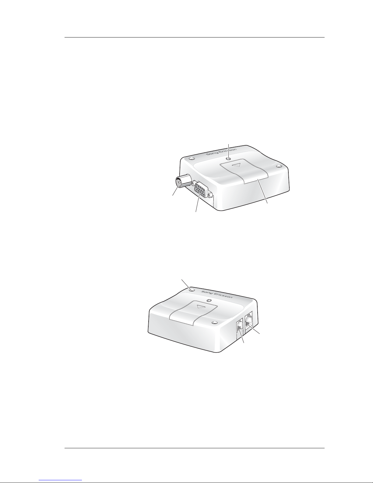
The pictures below show the mechanical design of the module along with
the positions of the different connectors and mounting holes. The module
case is made of durable PC/ABS plastic.
Figure 2.1 Module viewed from the left side
Figure 2.2 Module viewed from the right side
A
ntenna
connector
RS232 serial and
extended I/O connector
LED
Access to
SIM card
Mounting hole (x2)
Audio
connector
Power supply and
extended I/O connecto
r
Page 11
2. MECHANICAL DESCR I PTIO N
11
LZT 123 7607 R1B
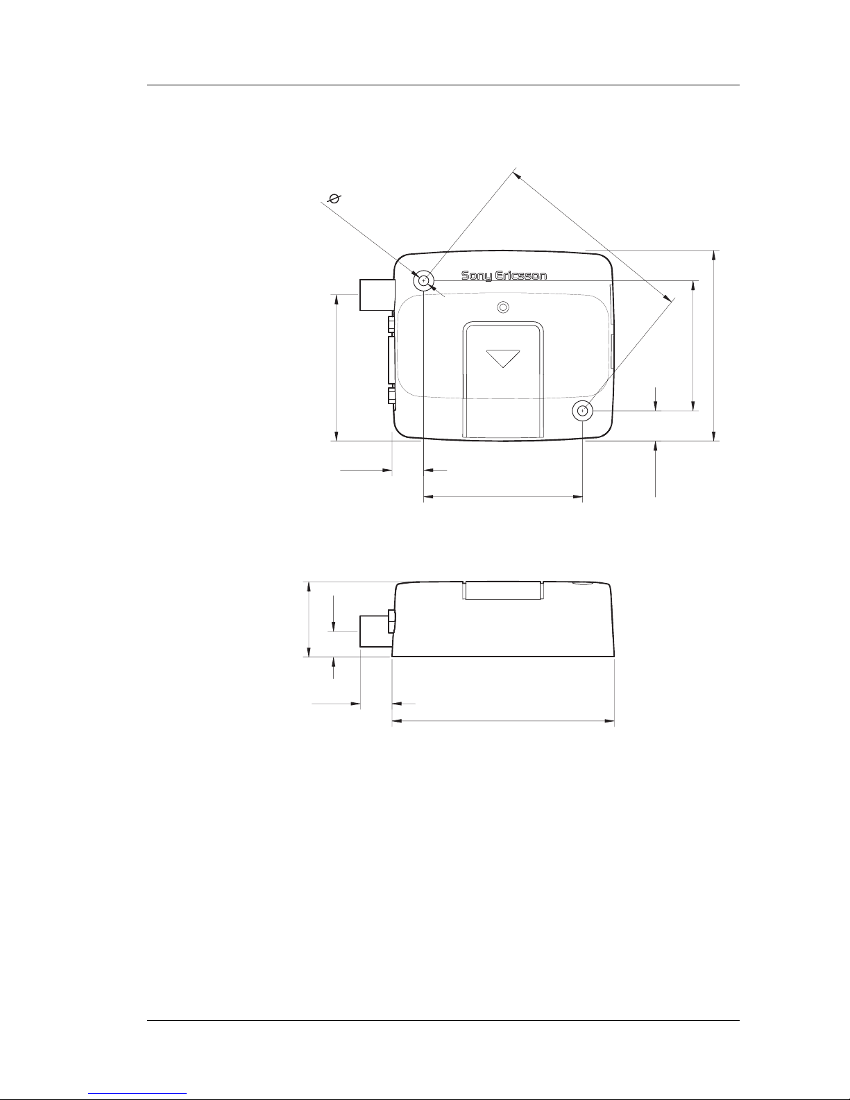
2.2 Physical Dimensions
Measurements are given in millimetres. See also “Technical Data”, page 32.
71.5
66.4
77.4
26.2
11.0
55.3
45.3
10.6
11.0
9.0
51.0
(x2)
3.5
Page 12
3. ELECTRICAL DESCRIPTION
12
LZT 123 7607 R1B
3. Electrical Description
All electrical connections to the module are protected in compliance with
the standard air (8
kV) and contact (4 kV) Electrostatic Discharge (ESD)
tests, of EN 61000-4-2.
The module uses the following industry standard connectors:
• High density 15 pin (RS232 serial and extended I/O interface)
• RJ12 6-way (power supply and extended I/O connector)
• RJ9 4-way (handset connector)
• SIM card reader
• FME male coaxial jack (antenna connector)
3.1 Power Supply and Extended I/O Connector
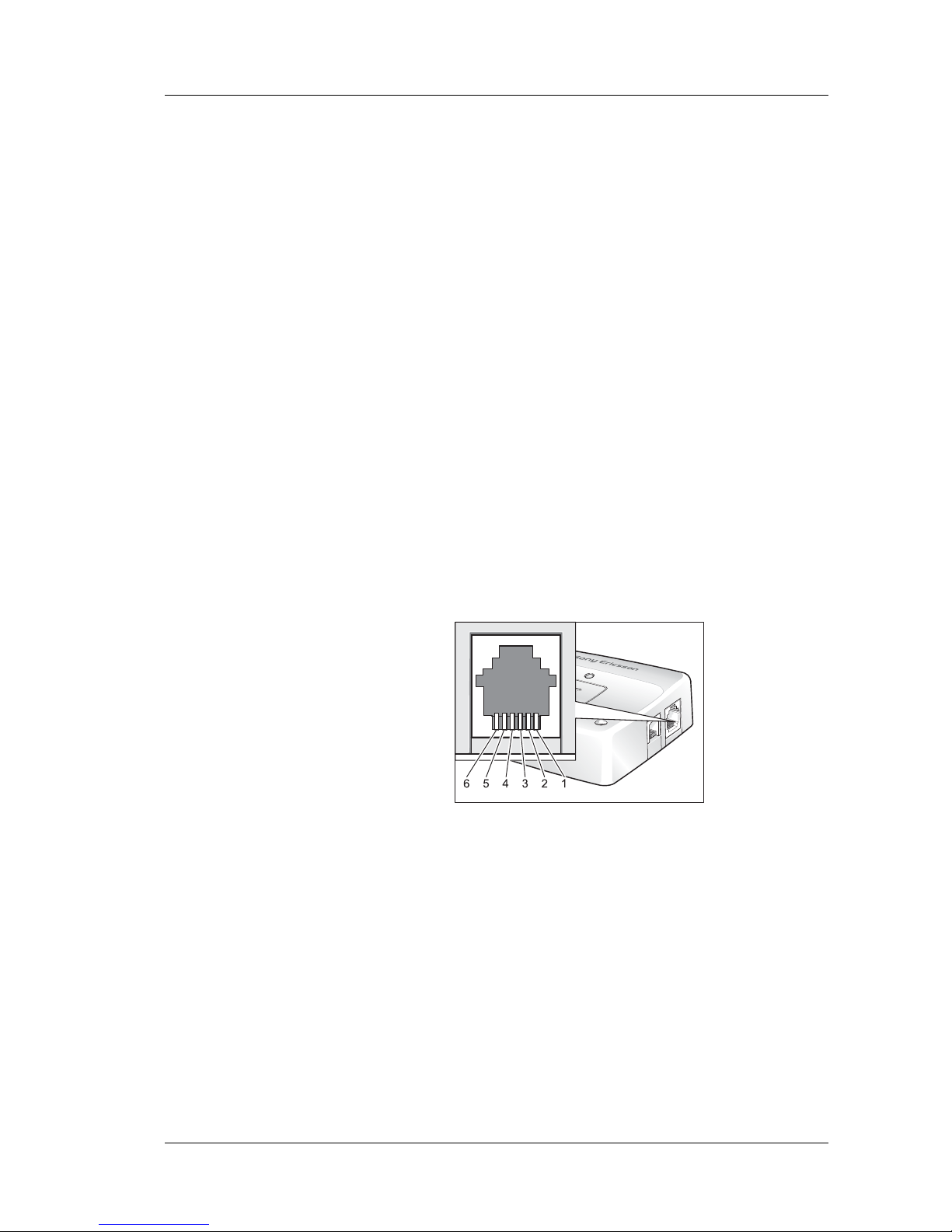
An RJ12 6-way connector, as shown and described below, serves as a means
of supplying and controlling d.c. power to the modem. Additionally there
are several extended input/output signals available that can be used to
control or interface external systems and devices.
General signal description:
1 V
IN
2 OUT-2
3 IN-1
4 TO_IN
5 OUT-1
6 GND
Page 13

3. ELECTRICAL DESCRIPTION
13
LZT 123 7607 R1B
The power connector electrical characteristics are listed below:
Note! Signal OUT-2 on the RJ12 connector is switched in parallel to signal
OUT-4 on the 15-pin high density socket. The individual output signals
are generated by two different low side switches inside the module driven
from a common control signal.
3.1.1 Power Supply Interface
The supply voltage VIN, required by the GT47, is in the range 5V - 32V
d.c. V
IN
and GND are reverse polarity and over voltage protected.
The GT47 switches on automatically once the 5V-32V dc supply voltage
is applied.
Note! The GT47 will not switch on if TO_IN is shorted to ground when the dc
supply is applied.
Note! For more information on switching the GT47 on and off please see section
“6. Operation”, page 30.
Note! Please be aware that the total current carried via either the V
IN
or GND
pins will be the sum of the intrinsic power consumption of the GT47 and
any drive current supplied via OUT-1 or OUT-2 (or other IOs). The
current on either of the VIN or GND pins must not exceed 1.5A.
Caution! It is recommended that the system integrator provides appropriate fusing
otherwise the GT47 may be damaged.
Pin Signal Dir Limits Description
1 V
IN
I 5 - 32 V Positive p ower input
2 OUT-2 O 32V, 0.25A Low side switch, short circuit protected
3 IN-1 I –0.5 - 32 V Digital Input
VIH > 3V, VIL < 2.8 V
Internal Pull Down of 40KΩ
4 TO_IN I –0.5 - 32 V Active low control line used to switch
the GT47 off/on.
VIH > 5 V, VIL < 2 V
Power off/on: t > 0.2 s
Internal Pull Up to VIN of 20KΩ
5 OUT-1 O VIN, 0.4A High side switch, short circuit protected
6 GND I - Negative power (groun d) input and
return path for TO_IN and the extended
inputs and outputs
Page 14
3. ELECTRICAL DESCRIPTION
14
LZT 123 7607 R1B
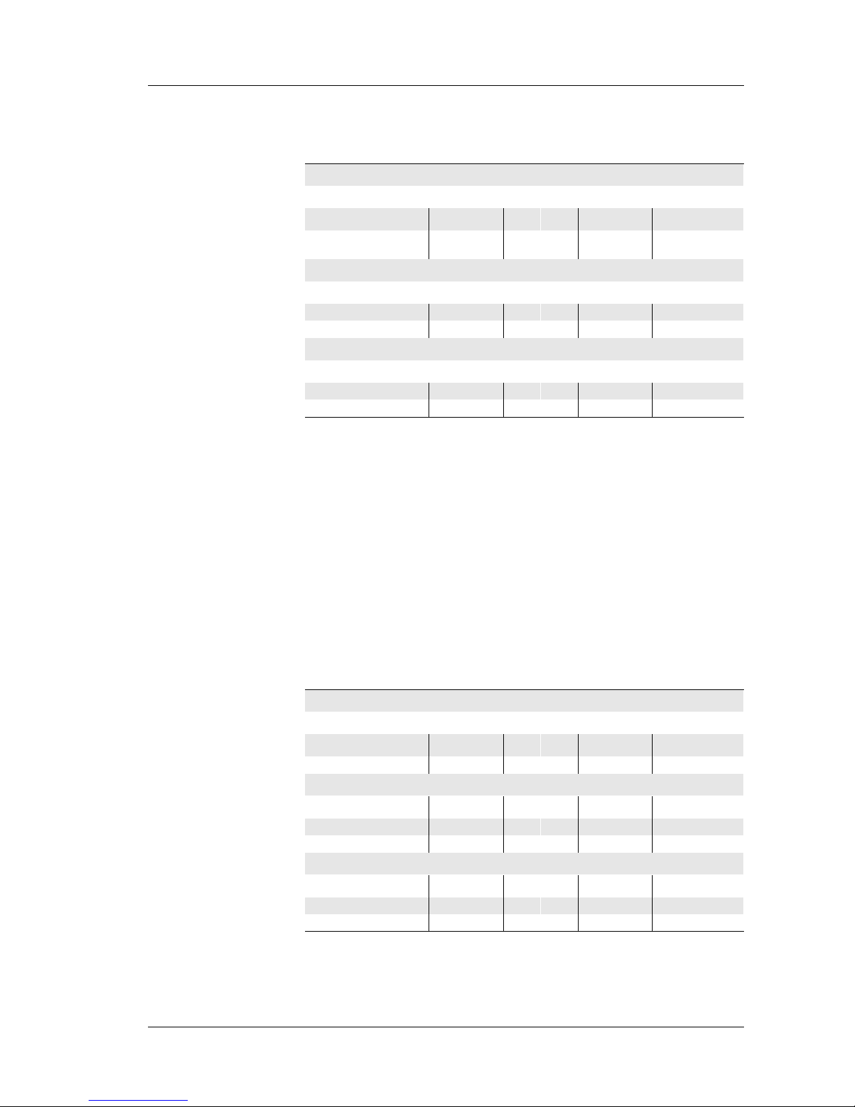
Current Consumption at Standard Operation
Notes! Power Down Mode: DC power is applied but the GT47 is switched OFF.
Standby Mode: The module is switched ON and camped on to the
network. No call in progress.
Talk Mode: The module is switched ON and a voice/data call is in
progress.
The power consumption during transmission in Talk Mode is measured at
maximum transmitted power.
The power consumption in Standby Mode is measured at the maximum
paging rate (Paging Rate 2).
Current Consumption with external +4.8V Supply Active
For the following calculations it was assumed that the external +4.8V load
is 70mA.
Note! These tables do not include the power consumption associated with any
drive current supplied via further GT47 outputs, e.g. OUT-1 or OUT-2.
Supply Voltage 5V 12V 32V
Power Down Mode:
AV Max AV Max AV Max
5 15 5 15 20 50
mA
Standby Mode (typical):
Frequency AV Max AV Max AV Max
850/900 MHz 26 110 9 43 6 20 mA
1900/1800 MHz 26 120 9 45 6 19 mA
Talk Mode (typical):
Frequency AV Max AV Max AV Max
850/900 MHz 220 1230 90 520 40 200 mA
1900/1800 MHz 170 960 70 350 30 140 mA
Supply Voltage 5V 12V 32V
Power Down Mode:
AV Max AV Max AV Max
5 15 5 15 20 50 mA
Standby Mode (typical):
Frequency AV Max AV Max AV Max
850/900 MHz 112 196 45 79 19 33 mA
1900/1800 MHz 112 206 45 81 19 32 mA
Talk Mode (typical):
Frequency AV Max AV Max AV Max
850/900 MHz 306 1316 126 556 53 213 mA
1900/1800 MHz 256 1046 106 386 43 153 mA
Page 15

3. ELECTRICAL DESCRIPTION
15
LZT 123 7607 R1B
([WHQGHG,26LJQDOV
Digital Inputs
The digital input IN-1 is available on pin 3 of the RJ12 connector. Its state
is detected by IO5 of the embedded GR47 engine, see GT47-GR47 signal
cross reference table, page 21.
The distinction between low level and high level signals is at the voltage
level of 3 V. Voltages above 3 V are detected as high level voltages and
voltages below 2.8 V are detected as low level.
Digital Outputs
The RJ12 power supply connector has two different output drivers:
• OUT-1 is driven by a high side switch that applies VIN to pin 5 of the
RJ12 connector. IO1 of the embedded GR47 engine is used to activate
the OUT-1 signal, see GT47-GR47 signal cross reference table,
page 21.
• OUT-2 is driven by a low side switch that shorts pin 2 of the RJ12
connector to ground when activated. IO3 of the embedded GR47
engine is used to activate OUT-2, see GT47-GR47 signal cross
reference table, page 21.
VIN Monitoring
The voltage, VIN, can be monitored internally by the GT47, for example if
the control terminal is supplied from an external battery. ADC1 on the
GR47 is used for this purpose, see GT47-GR47 signal cross reference table,
and is calibrated to operate in the voltage range 0 – 31.875 V. The
resolution of the 8 bit converter, ADC1, provides a measurement accuracy
of approximately 3%.
Page 16
3. ELECTRICAL DESCRIPTION
16
LZT 123 7607 R1B
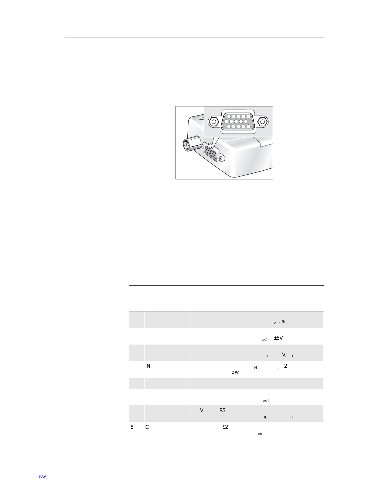
3.2 RS232 Serial and Extended I/O Interface
The GT47 supports a standard 9 signal RS232 serial interface (EIA/TIA
574) on the 15 pin high density connector together with a range of
configurabe I/Os including a second 4-wire RS232 interface.
Signals that support an alternative configuration can be reconfigured using
the appropriate AT command (e.g. AT+E2IO) or via an intrinsic function
if using an embedded application.
Note! When reconfiguring a GT47 signal, via AT command or intrinsic
function, the corresponding GR47 signal name must be used, see GT47GR47 signal cross reference table
, page 21.
The electrical characteristics of the serial port signals are shown below:
1 DCD
2 RD
3 TD
4 IN-3
5 OUT-3
6 DSR
7 RTS
8 CTS
9 4.8V
123
678
13 14
10
10 RI
11 IN-2
12 OUT-4
13 DTR
14 GND
15 ANA_IN
4
5
9
11
12
15
Pin GT47
Signal
Dir Max.
Voltage
limits
Description
1 DCD O ±13.2V RS232 signal
Data carrier detect V
RXW
≥ ±5V
2 RD O ±13.2V RS232 signal:
Received data V
RXW
≥ ±5V
3 TD I ± 25V RS232 signal:
Transmitted data V,/ < 0.6V, V,+ > 2.4V
4 IN-3 I -0.5 - 32V Digital input V,+ > 3V, V,/ < 2.8V
PullDown with 40KΩ
5 OUT-3 O 32V, 0.25A low side switch, short circuit protected
6 DSR O ±13.2V RS232 signal:
Data set ready V
RXW
≥ ±5V
7 RTS I ±25V RS232 signal:
Request to send V,/ < 0.6V, V,+ > 2.4V
8 CTS O ±13.2V RS23 2 s i gn al :
Clear to send V
RXW
≥ ±5V
Page 17
3. ELECTRICAL DESCRIPTION
17
LZT 123 7607 R1B
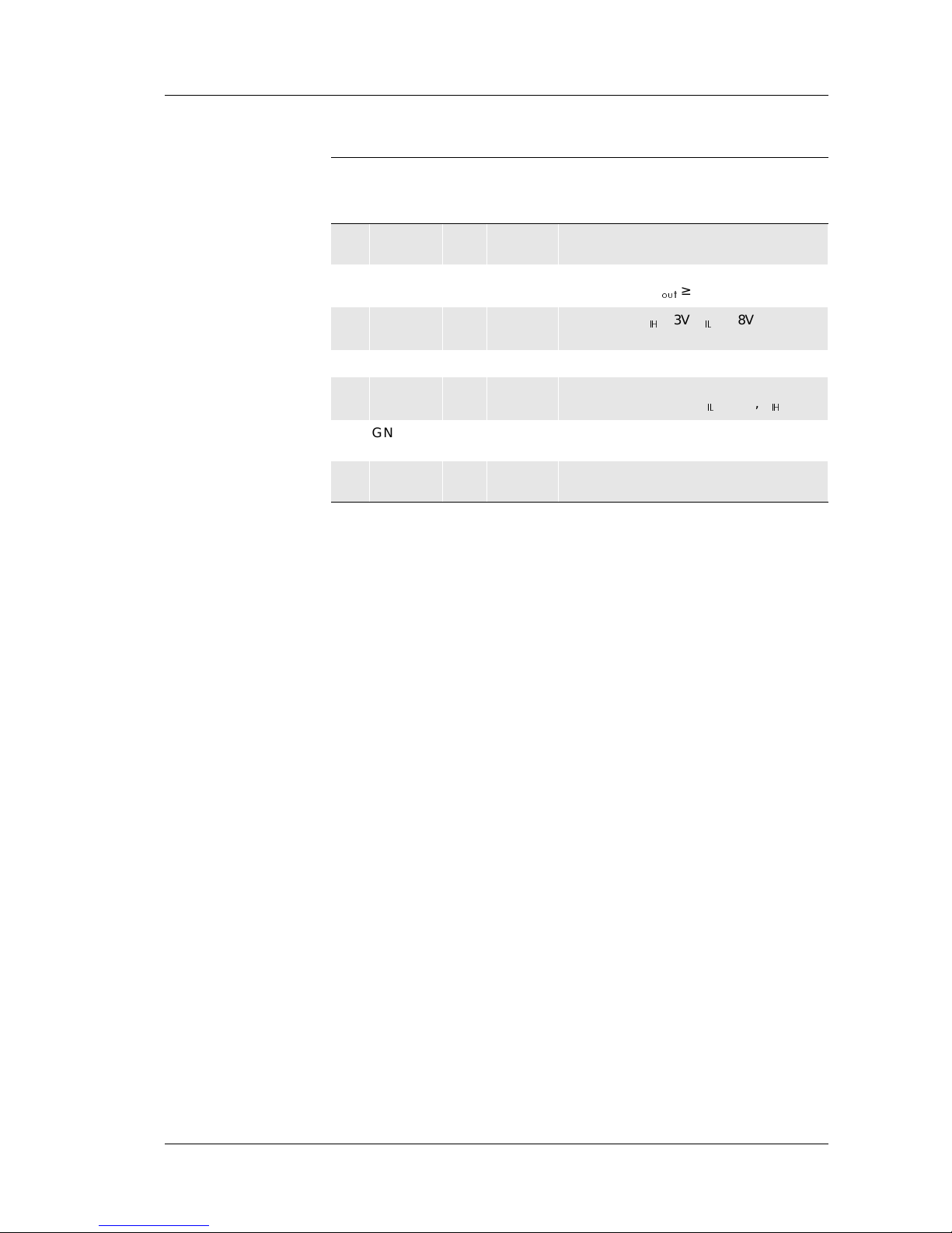
3.2.1 Standard RS 232 Serial interface and Signals
The module supports a standard RS232 serial interface (EIA/TIA 574) via
its 15 pin high density connector, shown above.
3.2.2 Serial Da t a
The GT47 supports the standard data character format of 1 start bit, 8 bit
data, no parity plus 1 stop bit, in total 10 bits per character. In line with
serial communication terminology the module is the data circuitterminating equipment (DCE) and the external application or computer is
the data terminating equipment (DTE).
3.2.3 Serial Data Signals - RD, TD
The default baud rate is 9.6 kbps, however higher bit rates up to 230.4 kbps
are supported and can be set by AT commands. At start-up the module
transmits and receives data at the default rate of 9.6 kbps in either standard
AT mode or binary mode (the first received data - AT or binary format determines the operating mode).
6HULDO'DWD)URP*75' 3LQ
RD is an output signal that the GT47 uses to send data to the external
application.
6HULDO'DWD7R*77' 3LQ
TD is an input signal, used by the external application to send data to the
GT47.
9 4.8V O 0 - +4.8V,
75mA
Voltage supply for external devices
Supply voltage +4.8V, max. current 75mA
10 RI O ±13.2V RS232 signal:
Ring indicator V
RXW
≥ ±5V
11 IN-2 I -0.5 - 32V Digital input V,+ > 3V, V,/ < 2.8V
PullDown with 40KΩ
12 OUT-4 O 32V, 0.25A low side switch, short circuit protected
13 DTR I ±25V RS232 signal:
Data Terminal Ready V,/ < 0.6V, V,+ > 2.4V
14 GND I - Ground connection and return path for
the extended inputs/outputs
15 ANA_IN I -0.5 - 32V Analog input measurement range: 0 -
12.75V
Pin GT47
Signal
Dir Max.
Voltage
limits
Description
Page 18

3. ELECTRICAL DESCRIPTION
18
LZT 123 7607 R1B
3.2.4 Control Signals - RTS, CTS, DTR, DSR, DCD, RI
RTS and CTS are capable of transmitting at 1/10 th of the data
transmission speed for data rates up to 230.4kbps (byte-oriented flow
control mechanism).
5HTXHVWWR6HQG576 3LQ
Used to condition the GT47 for data transmission. The default level is
inactive by internal pull down.
The exact behaviour of RTS is defined by an AT command. Software or
hardware control can be selected. Hardware flow is the default control.
The application must pull RTS high to enable transmission from the
GT47.
&OHDU7R6HQG&76 3LQ
CTS indicates that the GT47 is ready to transmit data. The default level is
high. You can define the exact behaviour of CTS through an AT command,
and can select software or hardware flow control.
'DWD7HUPLQDO5HDG\'75 3LQ
DTR indicates that the DTE is ready to send and receive data. It also acts
as a hardware ‘hang-up’, terminating calls when switched low. The signal
is active high. You can define the exact behaviour of DTR with an AT
command.
'DWD6HW5HDG\'65 3LQ
An active DSR signal is sent from the GT47 to the application (DTE) to
confirm that a communications path has been established. DSR has two
modes of operation, use the AT command AT&S to set the mode.
'DWD&DUULHU'HWHFW'&' 3LQ
DCD indicates that the GT47 is receiving a valid carrier (data signal) when
high. You can define the exact behaviour of DCD with an AT command.
5LQJ,QGLFDWRU5, 3LQ
RI indicates that a ringing signal is being received by the GT47 when
high. You can define the exact behaviour or RI with an AT command.
Page 19

3. ELECTRICAL DESCRIPTION
19
LZT 123 7607 R1B
Alternative Configuration
It is possible to reconfigure one or more of the signals in this section (RTS,
CTS, DTR, DSR DCD and RI) to be used as digital inputs or outputs if the
full RS232 serial interface is not required. Configuration is achieved using
AT command (AT+E2IO) or via embedded application intrinsic functions,
please refer to GT47-GR47 signal cross reference table, page 21.
To be reconfigured as a digital IO, each signal must retain the direction and
the logic voltage levels attributed to it when used as an RS232 signal. For
example DSR can only be reconfigured as a digital output with V
RXW
≥ ±5V.
3.2.5 Extended I/O Signals
Please refer to GT47-GR47 signal cross reference table, page 21, for more
information on the relationship between signal names and pin numbers of
the GT47 and the embedded GR47 engine.
'LJLWDO,QSXWV 3LQ
Digital inputs IN-2 and IN-3 are available on the HD15 connector via pins
11 and 4 respectively. The inputs are detected via signals IO4 and IO7 of
the embedded GR47 engine.
Note! As an alternative configuration signals IN-2 and IN-3 can be used to
support a second RS232 serial interface as RTS-2 and TD-2. Further
information is given below.
$QDORJ,QSXW 3LQ
The signal ANA_IN can be used for measuring analog input values in the
range 0 -12.75V. ADC2 of the embedded GR47 is used to detect
ANA_IN.
The resolution of the converter is 8 bit with an measurement accuracy of
about 3%.
The input impedance of the ANA_IN pin is 50 KΩ.
'LJLWDO2XWSXWV 3LQ
Digital outputs OUT-3 and OUT-4 are available on the HD15 connector
via pins 5 and 12 respectively. The outputs are controlled via signals IO8
and IO3 of the embedded GR47 engine.
Signal OUT-4 on the HD15 connector is switched in parallel to signal
OUT-2 on the RJ12 connector. The individual output signals are
generated by two different low side switches inside the terminal driven
from the common control signal, IO3. All GT47 output signals driven by
Page 20

3. ELECTRICAL DESCRIPTION
20
LZT 123 7607 R1B
low side switches return to open circuit when deactivated. This allows the
external application hardware to determine the desired logic voltage levels
with the appropriate pull-up.
The output drivers are low side switches which short the pin to GND if
they are activated.
Note! As an alternative configuration signals OUT-3 and OUT-4 can be used to
support a second RS232 serial interface as CTS-2 and RD-2. Further
information is given below.
92XWSXW6XSSO\ 3LQ
There is a voltage regulator implemented inside the module that is capable
of supplying an external voltage source of +4.8V with a maximum current
of 75 mA.
The voltage source can be switched on/off with the DAC signal of the
internal GR47 GSM engine.
By default the voltage source is switched on. A high level of 2.75V at the
DAC output of the GR47 GSM engine will switch the voltage source off.
Note! The +4.8V source may be switched on/off via an embedded or external
application and so may be used as an optional digital output with levels of
+4.8V and open circuit.
3.2.6 Second RS232 Serial Interface
IN-3 and OUT-3 can be automatically reconfigured as signals TD-2 and
RD-2, of a second serial interface, by enabling UART3 of the internal
GR47. UART 3 may be enabled using AT command or intrinsic function.
In addition, IN-2 and OUT-4 can be automatically reconfigured as signals
CTS-2 and RTS-2 of the second serial interface by enabling hardware flow
control for UART3 on the internal GR47. Hardware flow control can be
enabled using intrinsic function only.
Note! The signal level thresholds for each of the digital inputs of the second serial
interface are: 3V<V,+<32V and V,/< 2.8V.
An external RS232 transceiver component may be used to convert the serial
interface to standard RS232 electrical levels. The GT47’s +4.8 V output
can be used to provide power for the transceiver.
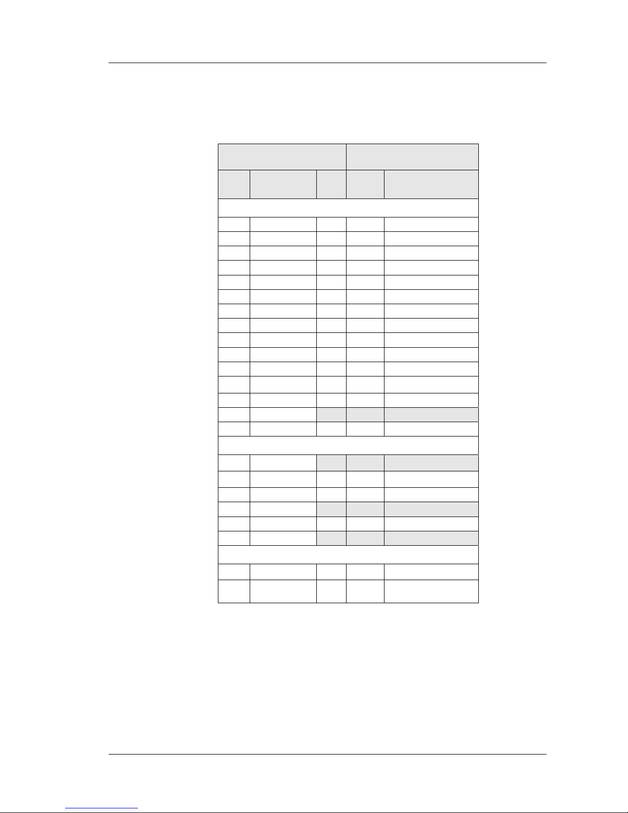
3.2.7 Relationship between GT47 and GR47 signals
When reconfiguring a GT47 signal, via AT command or intrinsic
function, the corresponding GR47 signal name must be used, see the
GT47-GR47 signal cross reference tables overleaf.
Page 21
3. ELECTRICAL DESCRIPTION
21
LZT 123 7607 R1B
GT47 - GR47 Signal Cross-reference Table A
†
IO3 on the embedded GR47 provides the common control signal for both
GT47 signals OUT-2 and OUT-4.
GT47 / GT48 Relationship to the
GR47/GR48 engine
GT47
Pin
GT47 Primary
Signal
Dir.
GR47
Pin
Corresponding GR47
Signal
HD15 Connector
1 DCD O 38 DCD
2 RD I 42 RD
3 TD O 41 TD
4 IN-3 I 43 IO7
5 OUT-3 O 44 IO8
6 DSR O 32 DSR
7 RTS I 39 RTS
8 CTS O 40 CTS
9 +4.8V O 20 DAC
10 RI O 36 RI
11 IN-2 I 24 IO4
12 OUT-4 O 23
IO3
†
13 DTR I 37 DTR
14 GND
15 ANA_IN I 27 ADC2
RJ12 Connector
1 V
IN
2 OUT-2 O 23
IO3
†
3 IN-1 I 13 I05
4 TO_IN
5 OUT-1 O 21 IO1
6 GND
GT47 Internal Function
V
IN
Monitoring I 26 ADC1
Power Save
Mode
O 22 IO2
Page 22
3. ELECTRICAL DESCRIPTION
22
LZT 123 7607 R1B
GT47-GR47 Signal Cross-reference Table B
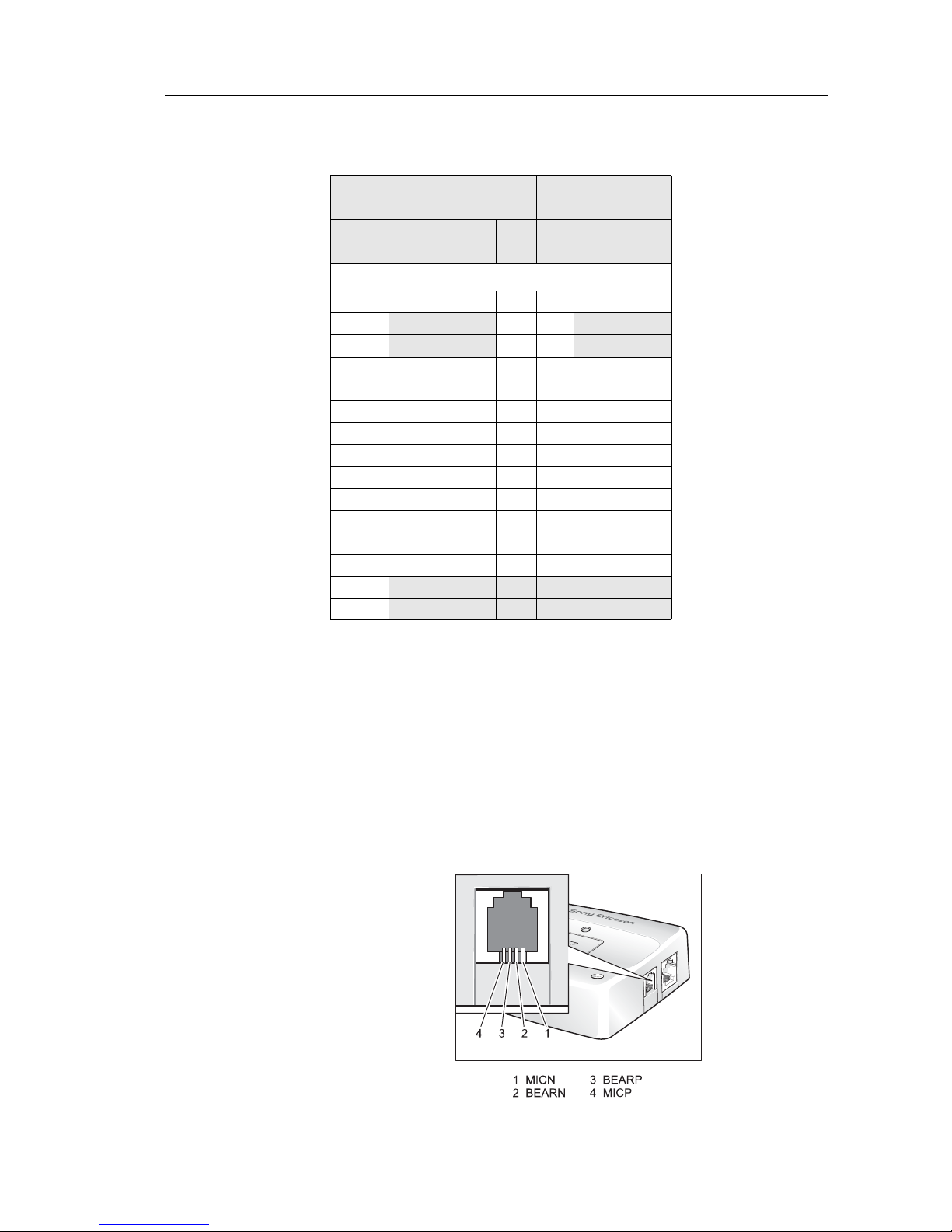
3.3 Audio Connector
A 4-way RJ9 connector, as shown below, allows a telephone handset to be
plugged into the GT47, giving access to the microphone and earpiece
signals. The connector may also be used to drive other analogue audio subsystems or devices.
The module is configured to work with a range of handsets. If necessary,
changes can be made to the characteristics of the audio interface by sending
the GT47 appropriate AT commands.
GT47 / GT48 Relationship to
GR47/GR48 engine
GT47
Pin
GT Alternative
signal
Dir. Pin Corresponding
GR47 Signal
HD15 Connector
1 OUT-6 O 38 O1
2 I 42
3 O 41
4 TD-2 I 43 TD3
5 RD-2 O 44 RD3
6 OUT-7 O 32 O3
7 IN-4 I 39 IO9
8 OUT-8 O 40 O4
9 OUT-5 O 20 DAC
10 OUT-9 O 36 O2
11 RTS-2 I 24 IO4
12 CTS-2 O 23 IO3
13 IN-5 I 37 IN1
14
15
Page 23

3. ELECTRICAL DESCRIPTION
23
LZT 123 7607 R1B
Audio signal descriptions are listed below:
MICP and MICN are balanced differential microphone input signals.
These inputs are compatible with an electret microphone.
BEARP and BEARN are the speaker output signals. These are
differential-mode outputs. The electrical characteristics are given in the
table below.
The following table shows the ear piece impedances that can be connected
to BEARP and BEARN.
Pin Signal Dir Description
1 MICN I Microphone negative input
2 BEARN O Earpiec e negative output
3 BEARP O Earpiece positive output
4 MICP I Microphone positive input
Parameter Limit
Output level (differential) ≥ 4.0 V
SS
Output level (dynamic load = 32 Ω) ≥ 2.8 V
SS
Distortion at 1 kHz and maximum output level ≤ 5 %
Offset, BEARP to BEARN ± 30 mV
Ear piece mute switch atte nuation ≥ 40 dB
Ear piece model Impedance Tolerance
Dynamic ear piece [32 Ω + 800 µH] // 100 pF ± 20 %
Dynamic ear piece [150 Ω + 800 µH] // 100 pF ± 20 %
Piezo ear piece 1 kΩ + 60 nF ± 20 %
Page 24
3. ELECTRICAL DESCRIPTION
24
LZT 123 7607 R1B
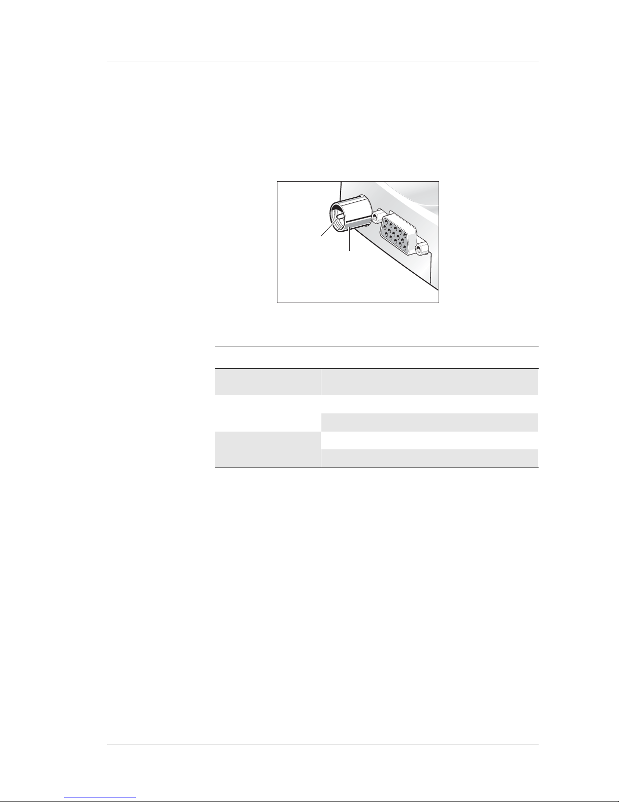
3.4 Antenna Connector
The antenna connector allows transmission of radio frequency (RF) signals
between the GT47 and an external customer-supplied antenna. The
module is fitted with a 50 Ω, FME male coaxial jack as shown below.
The table below shows the antenna electrical characteristics:
Parameter Limit Description
Nominal impedance 50 Ω (SWR better than
2.5:1)
Output Power
2 Watt peak (Class 4) EGSM 850/ 900
1 Watt peak (Class 1) GSM 1800/1900
Static Sensitivity
Better than –102 dBm EGSM 850/ 900
Better than –102 dBm GSM 1800/1900
RF Signal
GND
Page 25
3. ELECTRICAL DESCRIPTION
25
LZT 123 7607 R1B
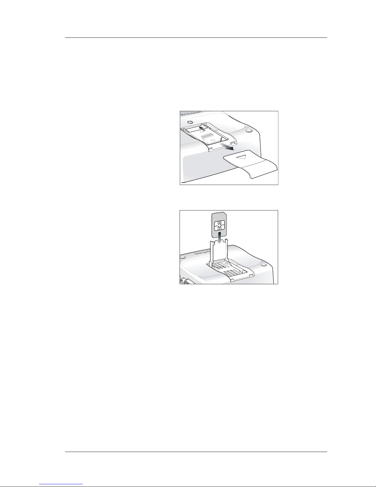
3.5 SIM Card Reader
The module is fitted with a SIM card reader designed for 3 V and 5 V SIM
cards. It is the flip-up type which is lockable in the horizontal position and
is accessed through a removable panel as shown below.
The SIM card reader incorporates a SIM presence switch which detects
whether a SIM card is inserted. The full operation of the GT47 relies on a
SIM card being inserted.
Caution! Some GT47 functionality may be lost if you try to operate the control
terminal without a SIM card.
The SIM presence switch also ensures that when a SIM card is inserted or
removed the unit is reset, as long as the GT47 is switched ON.
3.6 Real Time Clock
The module contains a real time clock (RTC) to maintain accurate
timekeeping and to enable “timestamping” of messages.
The RTC is powered all the time that the GT47 is turned on. When the
GT47 is powered off, a storage energy device within the module provides
back-up power to maintain the RTC for several hours - please contact Sony
Ericsson Customer Support for more information.
Page 26

3. ELECTRICAL DESCRIPTION
26
LZT 123 7607 R1B
3.7 Software Updates
It is possible, and sometimes necessary, to update the module software.
Updates must be carried out by a Sony Ericsson approved technician. Please
contact your supplier for details (see “Service and Support”, page 9).
Page 27

4. EMBEDDED APPLICATIONS
27
LZT 123 7607 R1B
4. Embedded Applications
The module has the capability to store and run customer written code in
the form of a script during the processors idle time, through the use of an
on board interpreter.
4.1 Features
Main features of embedded applications are as follows.
• C based scripting language (Sony Ericsson specific)
• Over the air upgrade of scripts (NOT GSM software)
• Library of intrinsic functions
• Multiple on radio device script support
4.2 Implementation
The module has up to 44kbytes of space available for storage of two scripts
in the scripting language and 25kbytes of operating RAM. Structures
included in this language are:
• If - then - else statements
• While loops
• For loops
All hardware interfaces that are normally available to the module through
the AT commands are available to the embedded application. Further
drivers have been written such as M bus and I2C for use by the embedded
application (EA) through the use of the I/O pins.
4.2.1 Limita tio n s
Since the module is processing the script using its own memory,
limitations are placed onto the scripts that are run.
• A direct comparison cannot be made to a fully compiled C program in
terms of size but a gauge of script size is that if each line were 128
characters long in the script then the script could be 350 lines long.
• Processing power is something that needs to be considered as the script
is run as a low priority process within the software. However, controller
mode stops GSM operation and provides all the processing power for
the script to be run. See the Application Guide for more details.
• Code cannot be ported directly from an existing application and loaded
directly onto the radio device. It must be re written in the Sony
Ericsson Mobile script language so that the radio device interpreter can
function correctly.
Page 28

4. EMBEDDED APPLICATIONS
28
LZT 123 7607 R1B
4.2.2 M2mpower IDE (Integrated Developers Environment)
The IDE is a windows based package which allows the user to write,
simulate, debug and download the application into a radio device with the
embedded application (EA) software. The standard version is designed to
run on Windows XP and 2000, other versions are available for 98 if
required.
A guide is available for implementing applications using the developers kit
and the embedded application (EA) functionality.
This is a required package to be able to implement an embedded
application (EA).
For further information please contact SEM customer support.
Page 29

5. TCP/IP STACK
29
LZT 123 7607 R1B
5. TCP/IP Stack
An on board IP/TCP/UDP stack has been integrated into the software
negating the need for the customer to implement one in their own code
base.
For early software releases this is only accessible through the embedded
applications (see previous section) using intrinsic functions.
5.1 Implementation
The following types of commands allow various functions:
• Open/closing IP connection - Negotiates/closes a dynamic IP address
with the web server.
• Send/Receive TCP packets - Performs all TCP operations to send and
receive packets.
• Send/Receive UDP packets - Performs all UDP operations to send and
receive packets.
• Resolve URL to an IP address - Similar to nslookup command in DOS
When the unit is set up and controlled using the embedded applications
either the embedded applications or an external application can generate
data to be sent and pass it to the radio device for transmission.
This effectively provides a transparent communication link to an internet
server from the application over GPRS.
Page 30
6. OPERATION
30
LZT 123 7607 R1B
6. Operation
6.1 Switching the GT47 On
The GT47 is turned ON automatically once DC power is applied. If the
GT47 is turned OFF, using one of the methods described in 6.2, the
control terminal can be turned ON again through one of two methods:
• pull signal TO_IN to ground for t >0.2s, then release.
• activate the main RS232 control line DTR, low to high for >0.2s
The GT47 is fully operational after 4 seconds. Logging onto a network may
take longer than this and is outside the control of the GT47.
Note! The GT47 will not switch on if TO_IN is shorted to ground when the dc
supply is applied.
6.2 Switching the GT47 Off
There are two ways to switch off the GT47 as described below.
• Use the appropriate AT command (AT+CFUN);
• pull signal TO_IN to ground for t >0.2s, then release.
6.3 Operating States/LED
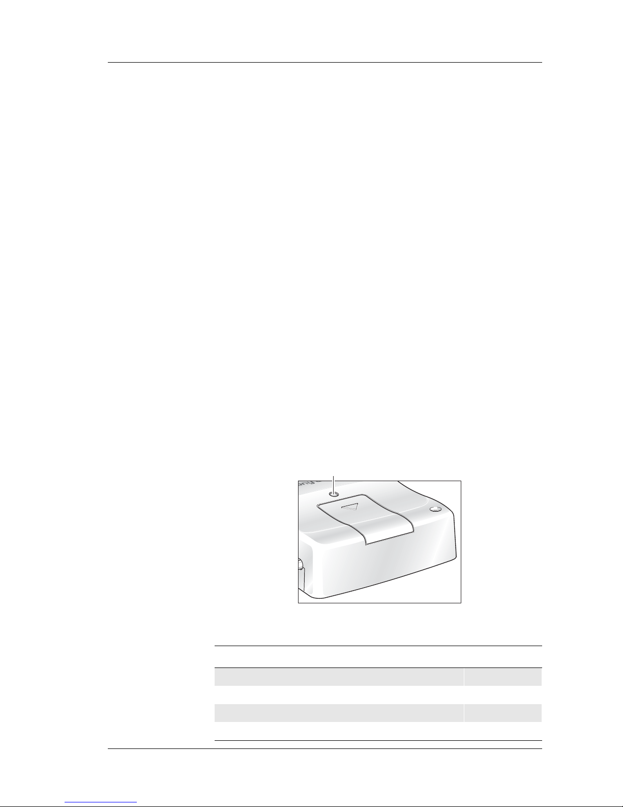
The GT47 has a green LED, as depicted below, which is used to indicate
various operating states. These states are described in following table.
Operating state LED
After switching on the GT47 On after 4 s
GT47 switched off or power removed from the module Off
Standby or talk Flashing
No network, network search, no SIM card, no PIN entered On
LED
Page 31

6. OPERATION
31
LZT 123 7607 R1B
6.4 Power Save
The GT47 can power down the main RS232 IC when not needed in order
to minimise power consumption. The IC is powered up automatically at
start-up but can be powered down by setting the output of IO2 on the
embedded GR47 (pin22) to low via AT command or embedded
application. Once powered down, the IC can be woken up by setting the
output of IO2 high on the GR47 via AT Command.
Even when powered down the IC is able to pass a DTR signal received on
the serial interface. Therefore an embedded application that monitors
DTR, while the IC is powered down, can be made to wake up the IC, if a
signal is received, by setting IO2 on the GR47 high.
6.5 Controller Mode
The GT47, when powered up, will normally start up its GSM signalling
software and look to register on the GSM network. Any embedded
application script runs as a background process as and when the GSM
software is idle. As a feature available via embedded applications the GT47
can be placed in ‘controller mode’ whereby the GT47 powers up with a
minimal subset of radio functionality. The GSM signalling software is
halted and the embedded applications script has full control of the
processor.
Controller mode allows an application to run with more predictable
response times.
Page 32

7. TECHNICAL DATA
32
LZT 123 7607 R1B
7. Technical Data
'DWD)HDWXUHV
6KRUW0HVVDJH6HUYLFH)HDWXUHV
9RLFH)HDWXUHV
)D[)HDWXUHV
CSD Up to 9.6 kbps, transparent and non-
transparent
HSCSD (2+1) Up to 28.8 kbps
GPRS Class B (4+1)
- P channels
- Coding schemes CS1 - CS4
85.6 kbps (subject to network support and
terminal location)
GSM 07.10 multiplexing protocol
SMS
Text and PDU
Point to point (MT/MO)
Cell broadcast
concatenation of up to 6 SMS
Full Rate, Enhanced Full Rate and Half Rate
(FR/EFR/HR)
Echo Cancellation and Noise Reduction
Dual Tone Multi Frequency (DTMF)
Group 3
Class 1 and 2
Page 33

7. TECHNICAL DATA
33
LZT 123 7607 R1B
'DWD6WRUDJH
3RZHU6XSSO\
5DGLR6SHFLILFDWLRQV
$XGLR6SHFLILFDWLRQV
SMS storage capacity 40 in the module
In addition, the unit can handle as many SMS
as the SIM can store
Phone book capacity 100
Supply voltage range 5 - 32 V d.c.
Frequency ran g e GT47: EGSM 900 MHz and 1800 MHz (dual band)
Maximum RF output
power
2 W (900 MHz) and 1 W (1800 MHz)
Antenna impedance 50 Ω
Static sensitivity Better than –102 dBm
Parameter Limit
Output level (differential) ≥ 4.0 V
SS
Output level (dynamic load = 32 Ω) ≥ 2.8 V
SS
Distortion at 1 kHz and maximum output level ≤ 5 %
Offset, BEARP to BEARN ± 30 mV
Ear-piece mute -s w i tc h at tenuation ≥ 40 dB
Ear piece model Impedance Tolerance
Dynamic ear piece [32 Ω + 800 µH] // 100 pF ± 20 %
Dynamic ear piece [150 Ω + 800 µH] // 100 pF ± 20 %
Piezo ear piece 1 kΩ + 60 nF ± 20 %
Page 34

7. TECHNICAL DATA
34
LZT 123 7607 R1B
6,0&DUG5HDGHU
(OHFWULFDO&RQQHFWRUVDQG/('
0HFKDQLFDO6SHFLILFDWLRQ
Voltage type Support for 3 V and 5 V SI M cards
Plug-in power supply
connector and extended I/O
RJ12 6-way
Handset audio connector RJ9 4-way
Antenna connector FME male
RS232 port high density socket, 15 pin
LED Green
Length 77.4 mm
Width 66.4 mm
Height 26.2 mm
Weight < 110 g
Page 35

7. TECHNICAL DATA
35
LZT 123 7607 R1B
(QYLURQPHQWDOVSHFLILFDWLRQV
&HUWLILFDWLRQ
Operating temperature
range
–30 °C to +75 °C
Storage temperature
range
–40 °C to +85 °C
Relative humidity 5 - 95 %, non-condensing
Stationary vibration,
sinusoidal
Displacement: 7.5 mm
Acceleration amplitude: 20 m/s² and 40 m/s²
Frequency ran ge: 2-8 Hz, 8-200 Hz, 200-500 Hz
Stationary vibration,
random
Acceleration spectral density (m²/s²):
0.96, 2.88, 0. 96
Frequency ran ge:
5-10 Hz, 10-200 Hz, 200-500 Hz, 60 min/axis
Non-stationary vibration,
including shock
Shock response spectrum I, peak acceleration:
3 shocks in each axis and direction;
300 m/s², 11 ms
Shock response spectrum II, peak acceleration:
3 shocks in each axis and direction;
1000 m/s², 6 ms
Bump Acceleration: 250 m/s²
Free fall transportation 1.2 m
Rolling pitching
transportation
Angle: ±35 degrees; period: 8 s
Static load 10 kPa
Low air pressure/high air
pressure
70 kPa/106 kPa
Directive 1999/5/ E C
EMC: EN 301 489-1
EMC: EN 301 489-7
Safety: EN 60950-1
GSM 3GPP TS 51.010-1
Tested according to GCF-CC
Page 36

8. AT COMMAND SUMMARY
36
LZT 123 7607 R1B
8. AT Command Summary
The AT standard is a line-oriented command language. AT is an
abbreviation of ATtention and it is always used to start sending a command
line from the terminal equipment (TE) to the terminal adaptor (TA).
The command line consists of a string of alphanumeric characters. It is sent
to the GT47 to instruct it to perform the commands specified by the
characters.
As the list of AT commands supported occasionally changes, it is wise to
check the latest listing with Sony Ericsson before starting any software
development (see
“Service and Support”, page 9).
The AT commands listed below are supported by the GR47/48 (italic)
within the GT47. Be aware that not all AT commands will perform valid
operations in the GT47 owing to its modified range of IOs.
AT Command Description
AT Attention Command
AT&C Circuit 109 (DCD) Control
AT&D Ci rcuit 108 (DTR) Response
AT&F Set to Factory Defined Configuration
AT&S Circuit 107 (DSR) response
AT&W Store User Profile
AT* List all Supported AT Commands
AT*E2APC Application Program Control
AT*E2APD Application Program Download
AT*E2APR M2M Audio Profile Manipulation
AT*E2CD Ericsson M2M Cell Description
AT*E2EAMS Ericsson M2M Audio Profile Modification
AT*E2EMM Ericsson M2M Engineering Monitoring Mode
AT*E2ESC M2M Escape Sequence Guard Time
AT*E2FAX Ericsson M2M Fax Comm. Baud Rate Modification
AT*E2IO Ericsson M2M Input/Output Read/Write
AT*E2OTR Operational Temperature Reporting
AT*E2NBTS Ericsson M2M Neighbour BTS
AT*E2NMPR Ericsson M2M Set NMEA (GPS) Port Rate
AT*E2PBCS Ericsson M2M Phonebook Check Sum
AT*E2PHFB Portable Handsfree Button Sense Enable
Page 37

8. AT COMMAND SUMMARY
37
LZT 123 7607 R1B
AT*E2SMSRI Ri ng Indicator for SMS
AT*E2SPI Se rial Peripheral Interf ace
AT*E2SPN M2M Service Provider Indication
A T*E2SSD M2M Supplementary Service Dispatch
A T*E2SSI M2M Supplementary Service Indications
A T*E2SSN Ericsson M2M SIM Serial Number
AT*E2STKC M2M STK Set Up Call
AT*E2STKD M2M STK Display Text
AT*E2STKG M2M STK Get Inkey
AT*E2STKI M2M STK Get Input
AT*E2STKL M2M STK Select Item
AT*E2STKM M2M STK Set Up Menu
AT*E2STKN M2M STK Envelope (Menu Selection)
AT*E2STKS SIM Application Toolkit Settings
AT*E2STKTO SIM Application Toolkit Settings
AT*EALR Ericsson Audio Line Request
AT*EALS Ericsson Request ALS Status
AT*EAMS Ericsson Audio Mode Selection
AT*EARS Ericsson Audio Ring Signal
AT*ECAM Ericsson Call Monitoring
AT*ECPI Ciphering Indicator
AT*ECSP Ericsson Customer Service Profile
AT*EDIF Ericsson Divert Function
AT*EDST Ericsson Daylight Saving Time
AT*EENMEA NMEA (GPS) Mode on UART2
AT*EGIR Ericsson Group Item Read
AT*EIPS Identity Presentation Set
AT*ELAM Ericsson Local Audio Mode
AT*ELIN Ericsson Line Set
AT*EMAR Ericsson Master Reset
AT*EMIC Ericsson Microphone Mode
AT*EMIR Ericsson Music Mute Indication Request
AT*EPEE Ericsson Pin Event
AT Command De scription
Page 38

8. AT COMMAND SUMMARY
38
LZT 123 7607 R1B
AT*EPNR Ericsson Read SIM Preferred Network
AT*EPNW Ericsson Write SIM Preferre d Network
AT*ESAG Ericsson Add to Group
AT*ESCG Ericsson Create Group
AT*ESCN Ericsson Set Credit Card Number
AT*ESDG Ericsson Delete Group
AT*ESDI Ericsson Delete Group Item
AT*ESGR Ericsson Group Read
AT*ESIL Ericsson Silence Command
AT*ESLN Ericsson Set Line Name
AT*ESMA Ericsson Set Message Alert Sound
AT*ESMM Ericsson Settings Minute Minder
AT*ESNU Ericsson Settings Number
AT+CACM Accumulated Call Meter
AT+CALA Set Alarm
AT+CALD Alarm Delete
AT+CAMM Accumulated Call Meter Maximum
AT+CAOC Advice of C harge
AT+CBST Select Bearer Service Type
AT+CCFC Call Forwarding Number and Conditions
AT+CCLK Set Clock and Date
AT+CCWA Call Waiting
AT+CEER Extended Error Report
AT+CFUN Set ME Func tionality
AT+CGACT PDP C o ntext Activate or Deactivate
AT+CGATT GPRS Attach or Detach
AT+CGDATA Enter Data State
AT+CGDCONT Define PDP Context
AT+CGEREP GPRS Event Reporting
AT+CGMI Read MS Manufacturer Identification
AT+CGMM Read MS Model Identification
AT+CGMR Read MS Revision Identifi cation
AT+CGPADDR Show PDP Address
AT Command De scription
Page 39

8. AT COMMAND SUMMARY
39
LZT 123 7607 R1B
AT+CGQMIN Quality of Service Profile (Minimum Acceptable)
AT+CGQREQ Quality of Service Profile (Requested)
AT+CGREG GPRS Network Registration Status
AT+CGSMS Select Service for MO SMS Messages
AT+CGSN Read MS Product Serial Number Identification
AT+CHLD Call Hold and Multiparty
AT+CHSC HSCSD Current Call Parameters
AT+CHSD HSCSD Device Parameters
AT+CHSN HSCSD Non Transparent Call Configuration
AT+CHSR HSCSD Parameters Report
AT+CHSU HSCSD Automatic User Initiated Upgrading
AT+CHUP Hang Up Call
AT+CIMI Subscriber Identification
AT+CIND Indicator Control
AT+CLAC List All Available AT Commands
AT+CLCK Facility Lock
AT+CLIP Calling Line Identification
AT+CLIR Calling Line Identification Restriction
AT+CMEE Mobile Equipment Error
AT+CMER Mobile Equipment Event Reporting
AT+CMGC Send Command
AT+CMGD Delete Message
AT+CMGF Message Format
AT+CMGL List Message
AT+CMGR Read Message
AT+CMGS Send Message
AT+CMGW Write Message to Memory
AT+CMOD Call Mode
AT+CMSS Send From Storage
AT+CMUX Switch to 07.10 Multiplex Protocol
AT+CNMI New Message Indications to TE
AT+CNUM Subscriber Number
AT+COLP Connected Line Identification on Presentation
AT Command De scription
Page 40

8. AT COMMAND SUMMARY
40
LZT 123 7607 R1B
AT+COPS Operator Selection
AT+CPAS ME Ac ti v i ty St a tus
AT+CPBF Phonebook Find
AT+CPBR Phonebook Read
AT+CPBS ME Storage
AT+CPBW Phonebook Write
AT+CPIN PIN Control
AT+CPMS Preferred Message Storage
AT+CPUC Price Per Unit and Currency Table
AT+CPWD Change Password
AT+CR Service Reporting Control
AT+CRC Cellular Result Code
AT+CREG Network Registration
AT+CRES Restore SMS Settings
AT+CRLP Radio Link Protocol
AT+CSAS Save Settings
AT+CSCA Service Centre Address
AT+CSCB Select Cell Broadcast Message Type
AT+CSCS Select Character Set
AT+CSDH Show Text Mode Parameters
AT+CSMP Set Text Mode Parame ters
AT+CSMS Select Message Service
AT+CSQ Signal Strength
A T+CSSN Supplementary Service Notification
AT+CTZU Automatic Time Zone Update
AT+CUSD Unstructured Supplementary Service Data
AT+CVHU Voice Hang-Up
AT+F___ Low Level Fax Commands
AT+GMI Read Manufacturer Identification
AT+GMM Read Model Ide ntification
AT+GMR Read Revision Identification
AT+ICF Cable Interf ace Character Format
AT+IFC DTE-DCE Local Flow Control
AT Command De scription
Page 41

8. AT COMMAND SUMMARY
41
LZT 123 7607 R1B
AT+ILRR Cable Interface Local Rate Reporting
AT+IPR Cable Interface Port Command
AT+VTS DTMF and Tone Generation
AT+WS46 Mode Selection
ATA Answer
ATD Dial
ATE Command Echo
ATH Hang up
ATI Identification Information
ATL Monitor Speaker Loudness
ATM Monitor S peaker Control
ATO Return to Online Data Mode
ATP Select Pulse Dialling
ATQ Result Code Suppression
ATS0 Automatic Answer Con trol
ATS2 Escape Sequence Character
ATS3 Command Line Termination Character
ATS4 Response Formatting Character
ATS5 Command Line Editing Character (BACKSPACE)
ATS6 Blind Dial Delay Control
ATS7 Connection Completion Timeout
ATS8 Comma Dial Modifier Delay Control
ATS10 Automatic Disconnect Delay Control
ATT Select Tone Dialling
ATV DCE Response Format
ATX Call Progress Monitoring Control
ATZ Reset to Default Configuration
AT Command De scription
Page 42

9. ABBREVIATIONS AND DEFINITIONS
42
LZT 123 7607 R1B
9. Abbreviations and Definitions
Abbreviation Explanations
CBM Cell Broadcast Message
CBS Cell Broadcast Service
CSD Circuit Switched Data
DCE Data Circuit Terminating Equipment
DTE Data Terminal Equipment
DTMF Dual Tone Multi Frequency
EFR Enhanced Full Rate
EMC Electro-Magnetic Compatibility
ETSI European Telecommunication Standards Institute
FR Full Rate
GPRS General Packet Radio Service
GSM G lobal System f or Mobile Communication
High Side
Switch
Pin is driven high, to Vin, in the active state
HR Half Rate
HSCSD High Speed Circuit Switched Data
ITU-T International Telecommunication Union - Telecommunications
Standardisation Sector
Low Side
Switch
Pin is driven low in the active state. High state requires external pull up,
ME Mobile Equipment
MO Mobile Originated
MS Mobile Station
MT Mobile Terminated
PDU Protocol Data Unit
RLP Radio Link Protocol
RF Radio Frequency
RTC Real Time Clock
SIM Subscriber Identity Module
SMS Short Message Service
Page 43

9. ABBREVIATIONS AND DEFINITIONS
43
LZT 123 7607 R1B
TA Terminal Adapter
TE Terminal Equipment
TS Telecommunication Services
USSD Unstructured Supplementary Service Data
Abbreviation Explanations
 Loading...