

Page 1

Working Instruction, Mechanical
1210-5420 Rev1
Working Instruction, Mechanical
Applicable for G900
CONTENTS
1 Introduction ..............................................................................3
1.1 G900 ........................................................................................3
1.2 Equipment.................................................................................4
1.3 General cautions......................................................................5
1.4 Adhesives .................................................................................5
2 Disassembly .............................................................................6
2.1 Overview ...................................................................................7
2.1.1 Stylus ....................................................................................8
2.1.2 Battery Cover Assy & Battery................................................8
2.1.3 Camera Cover Assy..............................................................9
2.1.4 Front Assy and Keyboard....................................................10
2.1.5 Frame Assy.........................................................................12
2.1.6 Loudspeaker box and Sub PBA M2/SIM.............................12
2.1.7 Upper Flex Holder...............................................................13
2.1.8 Carrier LCD.........................................................................14
2.1.9 Display ................................................................................16
3 Replacements.........................................................................17
3.1 Stylus ...................................................................................... 18
3.2 Battery Cover Assy................................................................18
3.3 Battery.....................................................................................18
3.4 Camera Cover Assy ...............................................................18
3.5 Front Assy...............................................................................18
3.6 Frame Assy.............................................................................18
3.7 Keyboard.................................................................................18
3.8 Loudspeaker Box...................................................................19
3.9 M2/SIM Sub PBA.....................................................................19
3.10 Upper Flex Holder ..................................................................19
3.11 Carrier LCD .............................................................................19
3.12 Display.....................................................................................19
3.13 Gasket Loudspeaker..............................................................19
3.14 Gasket Camera.......................................................................20
3.15 Gasket Flash...........................................................................21
3.16 Gasket Mic ..............................................................................21
3.17 Gasket Q-Sif Camera..............................................................22
3.18 Light Guide .............................................................................23
3.19 Key On/Off...............................................................................23
3.20 Key Hold..................................................................................24
Company Internal
© Sony Ericsson Mobile Communicat i ons AB
Page 2

Working Instruction, Mechanical
1210-5420 Rev1 2(53)
3.21 Key Camera.............................................................................25
3.22 Key Volume.............................................................................25
3.23 Antenna Main Flex..................................................................26
3.24 Vibrator....................................................................................27
3.25 Flash Flex Assy......................................................................28
3.26 Ear speker...............................................................................31
3.27 Gasket ESD Top .....................................................................32
3.28 Volume Flex Assy...................................................................33
3.29 Grounding Cushions..............................................................34
3.30 Camera 5 MPixel.....................................................................35
3.31 Flex Keyboard Assy...............................................................36
3.32 Mic Gasket ..............................................................................37
3.33 BtB Gasket..............................................................................38
3.34 Camera Module QSIF.............................................................39
3.35 I/O Connector/Dust Gasket....................................................39
3.36 Thread Inserts.........................................................................40
3.37 Shield Cans x 5.......................................................................41
3.38 Liquid Intrusion Indicator......................................................42
3.39 Cushion 1,05 mm....................................................................43
3.40 ISP Cushion ............................................................................43
3.41 KRH Label ...............................................................................44
4 Reassembly ............................................................................44
4.1 Overview .................................................................................46
4.1.1 Display ................................................................................47
4.1.2 LCD Carrier.........................................................................47
4.1.3 Upper Flex Holder...............................................................48
4.1.4 M2/SIM Sub PBA and Loudspeaker box.............................49
4.1.5 Frame Assy.........................................................................50
4.1.6 Front Assy...........................................................................50
4.1.7 Camera Cover.....................................................................51
4.1.8 Battery and battery cover Assy ...........................................52
4.1.9 Stylos ..................................................................................52
5 Revision history.....................................................................53
Company Internal
© Sony Ericsson Mobile Communicat i ons AB
Page 3
Working Instruction, Mechanical
1210-5420 Rev1 3(53)
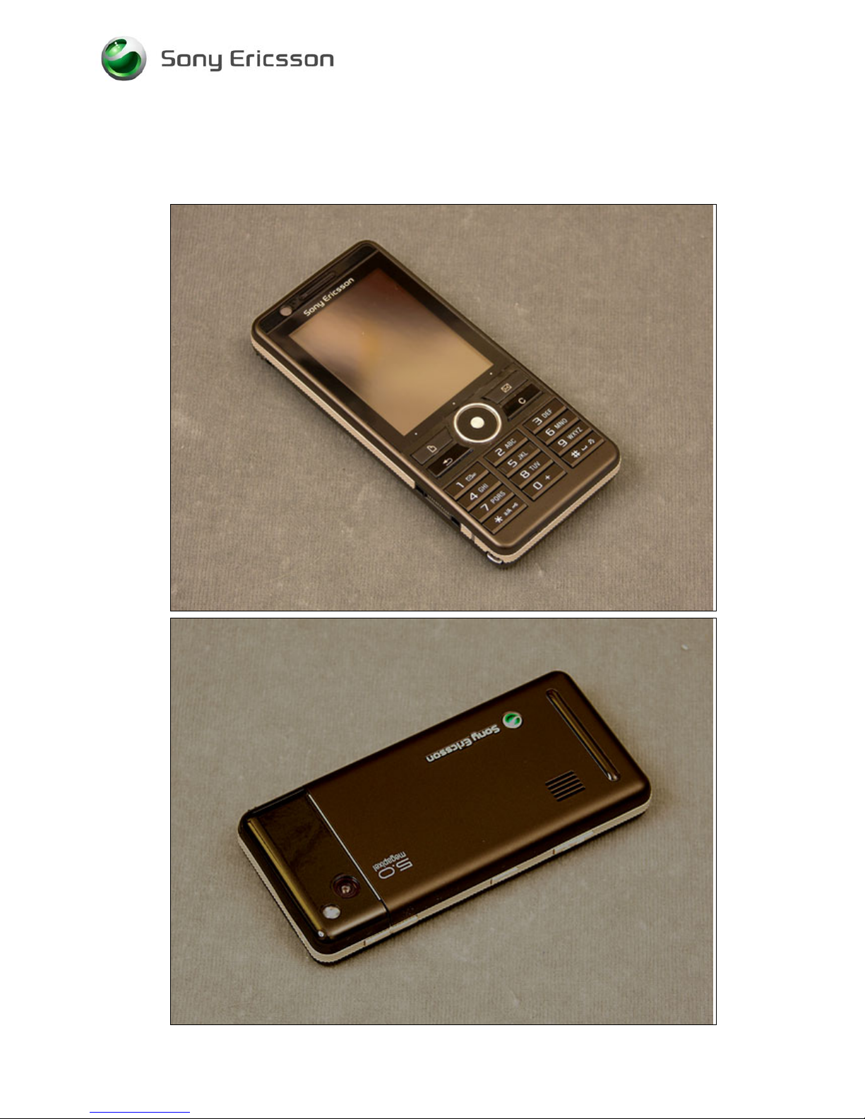
1 Introduction
1.1 G900
Company Internal
© Sony Ericsson Mobile Communicat i ons AB
Page 4
Working Instruction, Mechanical
1210-5420 Rev1 4(53)
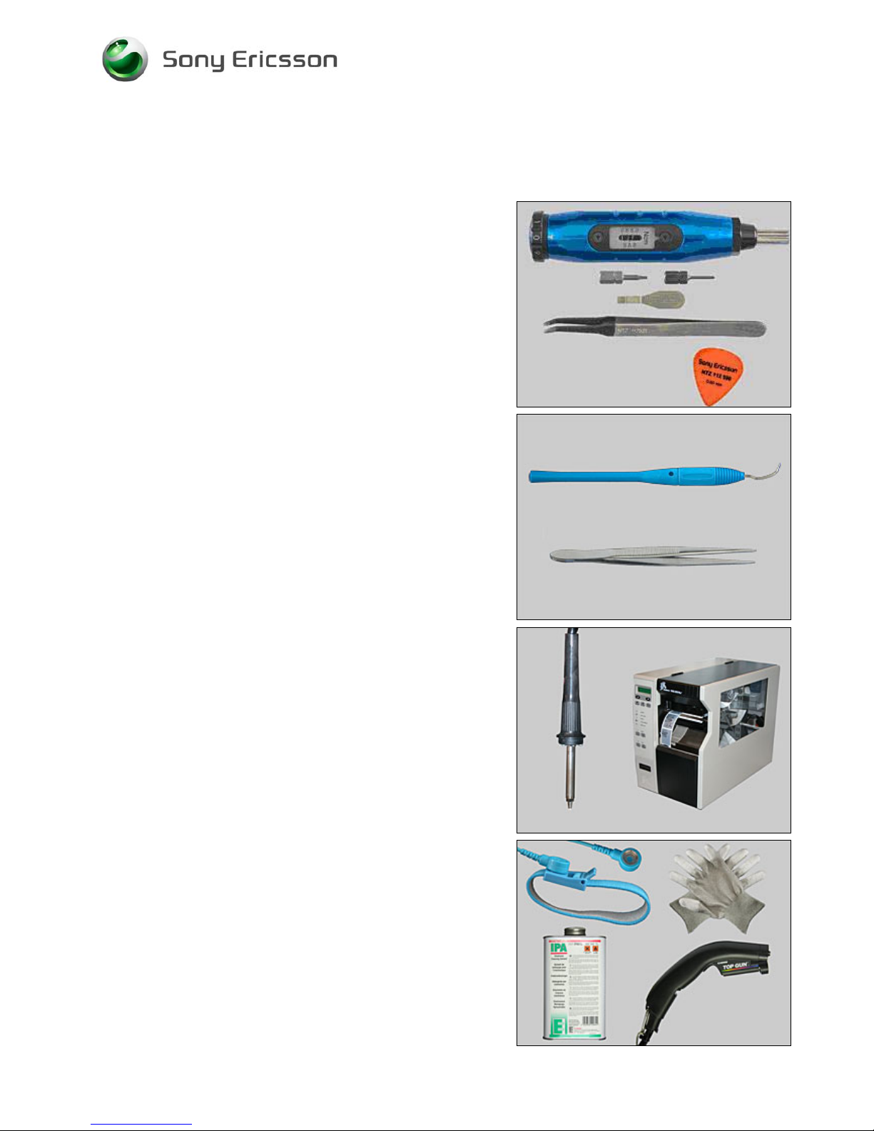
1.2 Equipment
SPECIAL TOOLS
• NTZ 122 459 Torque screwdriver (or equivalent)
• NTZ112478 Torx bit no. 5
• NTZ 122 288 Torx bit no. 6
• NTZ 112 302/2 Front opening tool
• NTZ 122 521 Flex film assembly tool
• NTZ 112 590 Guitar pick
STANDARD TOOLS
Standard tools have to be locally purchased
• Dentist hook
• ESD tweezers
LABEL EQUIPMENT
The following special equipment is required when replacing
or installing a new label:
• Hot air flow solder station
• Zebra printer connected to computer
OTHER EQUIPMENT
• ESD-wristband
• ESD-gloves
• Isopropyl alcohol
• Air blower
Company Internal
© Sony Ericsson Mobile Communicat i ons AB
Page 5

Working Instruction, Mechanical
1210-5420 Rev1 5(53)
1.3 General cautions
The following cautions are considered to be generic for all phone models and will not be repeated in
the Disassembly, Replacements and Reassembly sections:
• S
WITCH OFF THE PHONE AND REMOVE ANY MEMORY STICK BEFORE THE START OF THE DISASSEMBLY!
• KEEP ALL CONTACT SURFACES CLEAN!
• BE CAREFUL WHEN USING TOOLS LIKE THE DENTIST HOOK, TWEEZERS, OPENING TOOLS, GUITAR PICK
ETC. TO AVOID SCRATCHES OR DAMAGES TO THE EXTERIOR AND INTERIOR PARTS OF THE PHONE!
• B
E CAREFUL NOT TO DAMAGE ANY CONTACT SPRINGS!
• REMEMBER TO REMOVE THE PROTECTION FOILS ON NEW PARTS SUCH AS THE FRONT COVER AND LCD!
• NEVER TOUCH THE DISPLAY GLASS!
• U
SE AIR BLOW EQUIPMENT TO KEEP THE FRONT WINDOW AND DISPLAY MODULE DUST FREE!
1.4 Adhesives
Use a dentist hook and/or the tweezers to remove old adhesives.
Clean the surface with isopropyl alcohol before attaching new adhesives.
Company Internal
© Sony Ericsson Mobile Communicat i ons AB
Page 6
Working Instruction, Mechanical
1210-5420 Rev1 6(53)
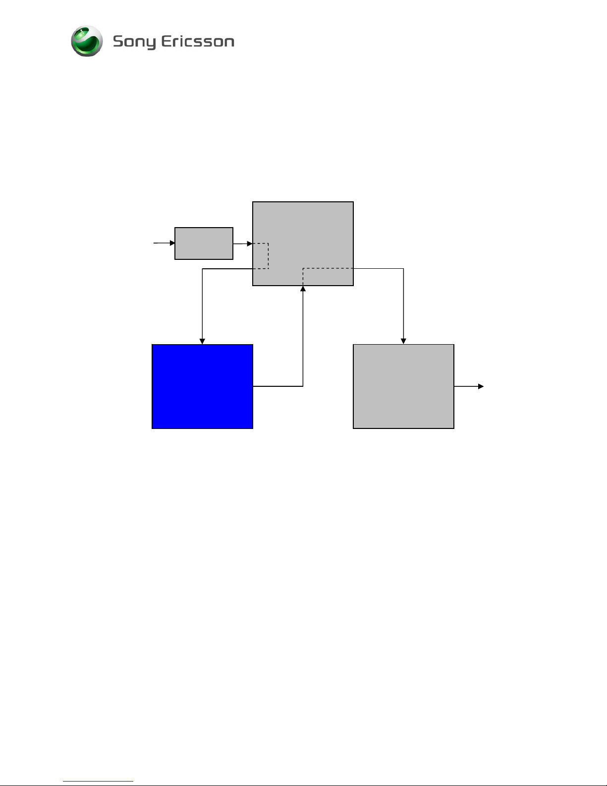
2 Disassembly
When you are going to replace a part being listed in Replacements, the instruction of that section
usually begins by directing you to this Disassembly section with a specification of the instructions you
have to carry out in order to disassemble the phone as far as needed before returning to
Replacements for the actual replacement.
Start
DISASSEMBLY
REASSEMBLY
Contents
page
REPLACEMENTS
Done
Company Internal
© Sony Ericsson Mobile Communicat i ons AB
Page 7
Working Instruction, Mechanical
1210-5420 Rev1 7(53)
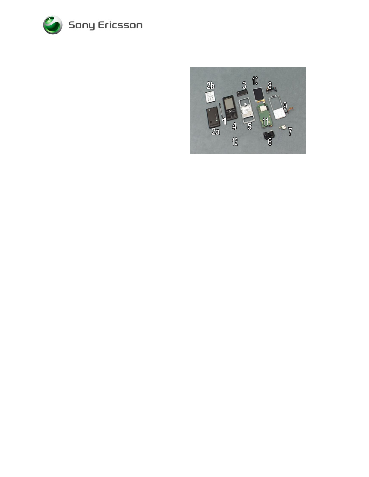
2.1 Overview
The disassembly is done in the following order:
1. Stylus
2. Battery Cover Assy (a) & Battery (b)
3. Camera Cover Assy
4. Front Assy and keyboard
5. Fame Assy
6. Loudspeaker Box
7. M2/SIM Sub PBA
8. Upper Flex Holder
9. LCD Carrier
10. Display
11. PBA
Company Internal
© Sony Ericsson Mobile Communicat i ons AB
Page 8
Working Instruction, Mechanical
1210-5420 Rev1 8(53)
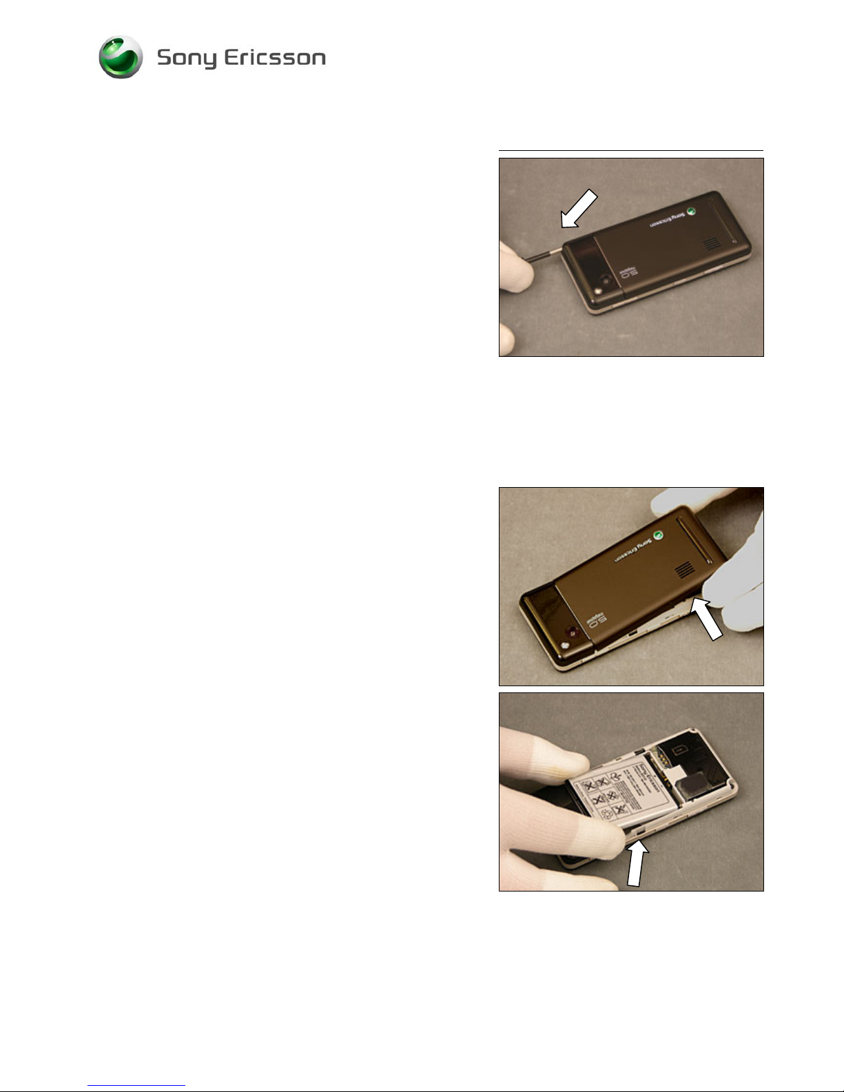
2.1.1 Stylus
Use your fingers to slide out the Stylus
2.1.2 Battery Cover Assy & Battery
Use your fingers to lift up the Battery Cover
Use your fingers to lift out the Battery
Company Internal
© Sony Ericsson Mobile Communicat i ons AB
Page 9
Working Instruction, Mechanical
1210-5420 Rev1 9(53)
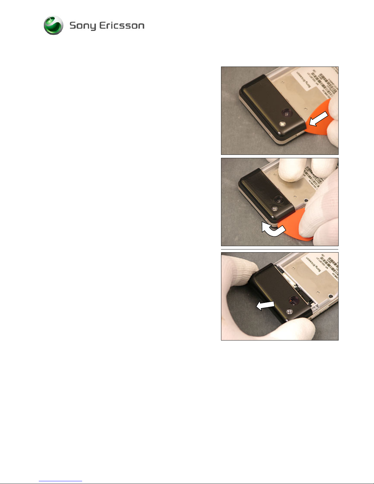
2.1.3 Camera Cover Assy
Use a guitar pick and slide it in as the picture shows.
Use a guitar pick and slide it upwards and around
Lift out the camera cover.
Company Internal
© Sony Ericsson Mobile Communicat i ons AB
Page 10
Working Instruction, Mechanical
1210-5420 Rev1 10(53)
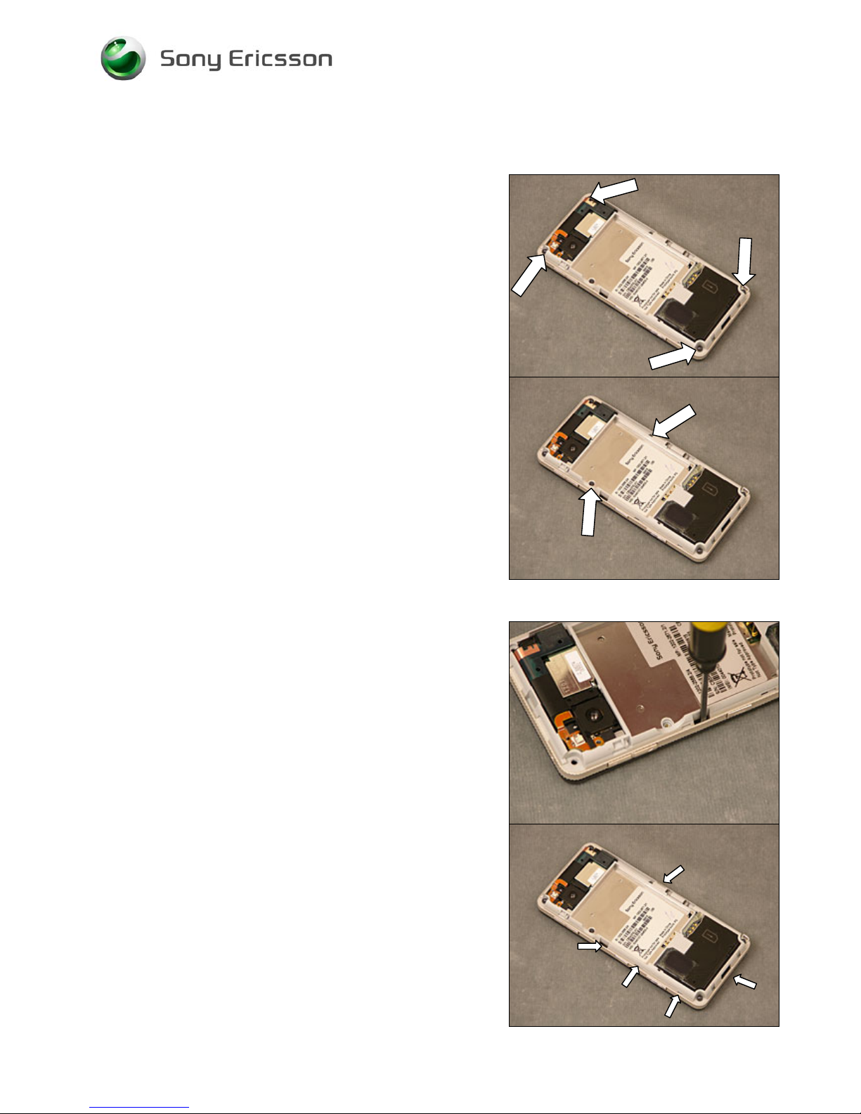
2.1.4 Front Assy and Keyboard
Use Torx bit no 6 to remove the four screws.
Use Torx bit no 5 to remove the two screws.
Use a screw driver to unsnap the 5 internal hooks.
Company Internal
© Sony Ericsson Mobile Communicat i ons AB
Page 11
Working Instruction, Mechanical
1210-5420 Rev1 11(53)
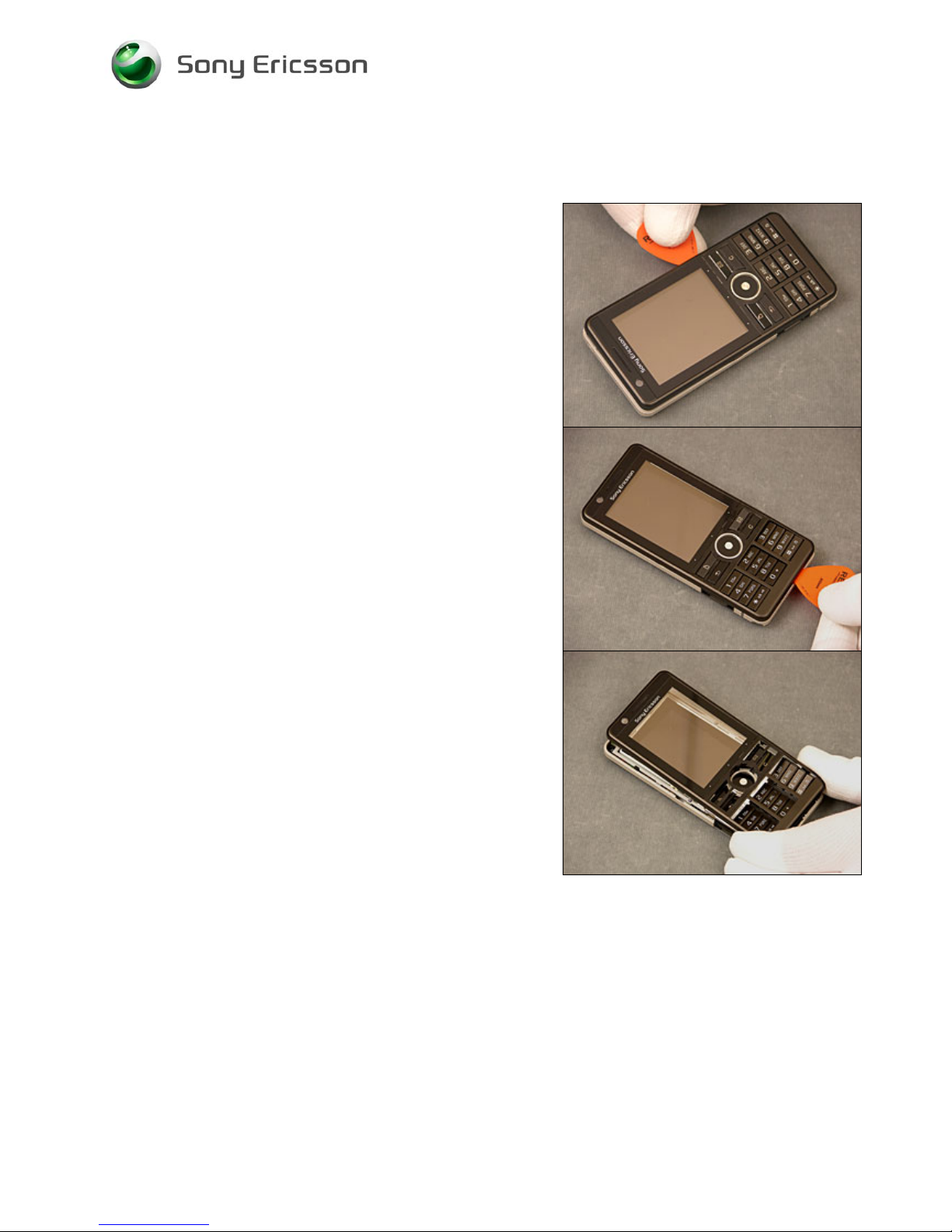
Use a guitar pic to unsnap the front.
Lift out the Front and the Keyboard
Company Internal
© Sony Ericsson Mobile Communicat i ons AB
Page 12
Working Instruction, Mechanical
1210-5420 Rev1 12(53)
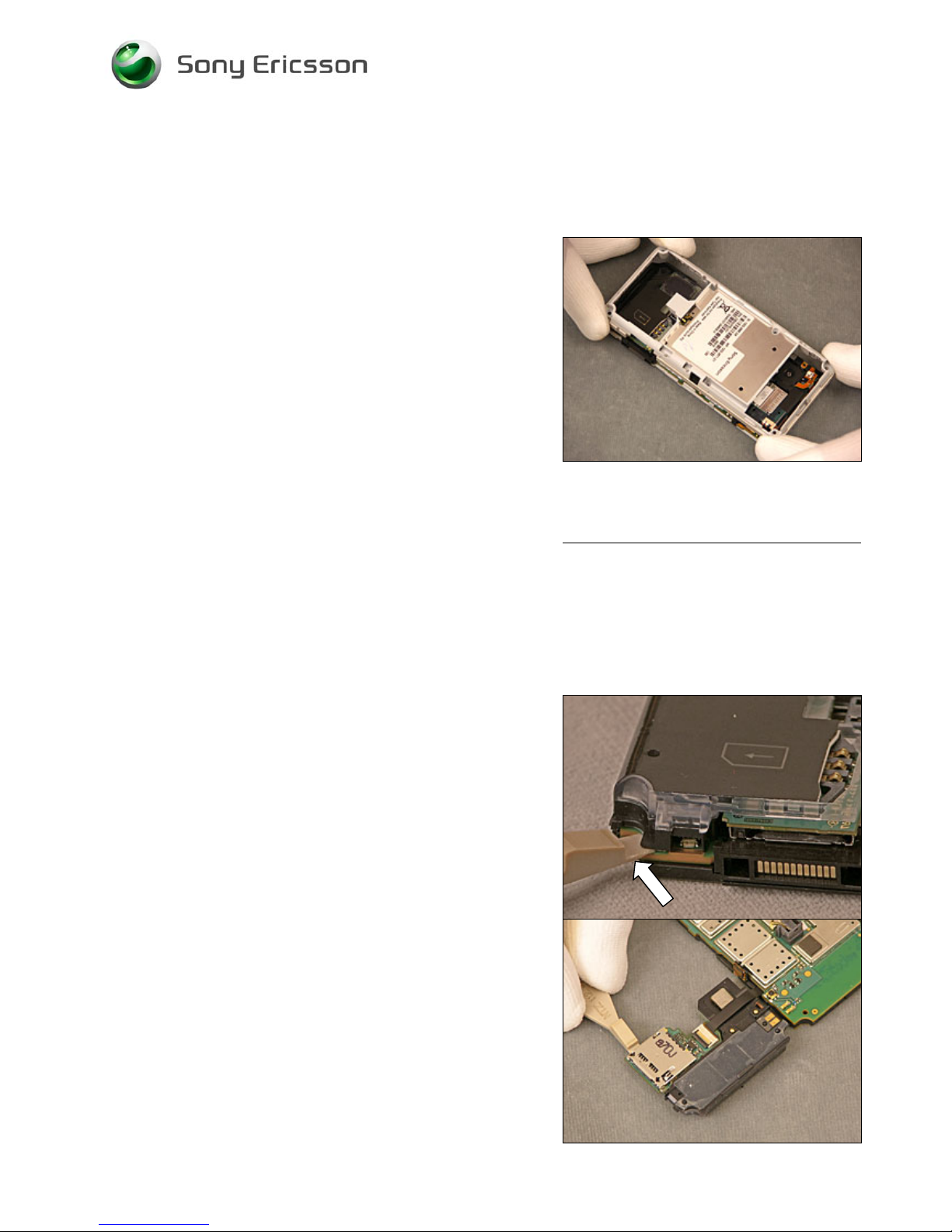
2.1.5 Frame Assy
Turn the phone around and lift of the Frame Assy
2.1.6 Loudspeaker box and Sub PBA M2/SIM
Go in over the Red/green LED with the Front Opening Tool
and bend up the speaker box from the PCB
Mind the Red/Green LED.
Bend up the M2/SIM Sub PBA with the Front Opening Tool
from the Speaker box
Company Internal
© Sony Ericsson Mobile Communicat i ons AB
Page 13
Working Instruction, Mechanical
1210-5420 Rev1 13(53)
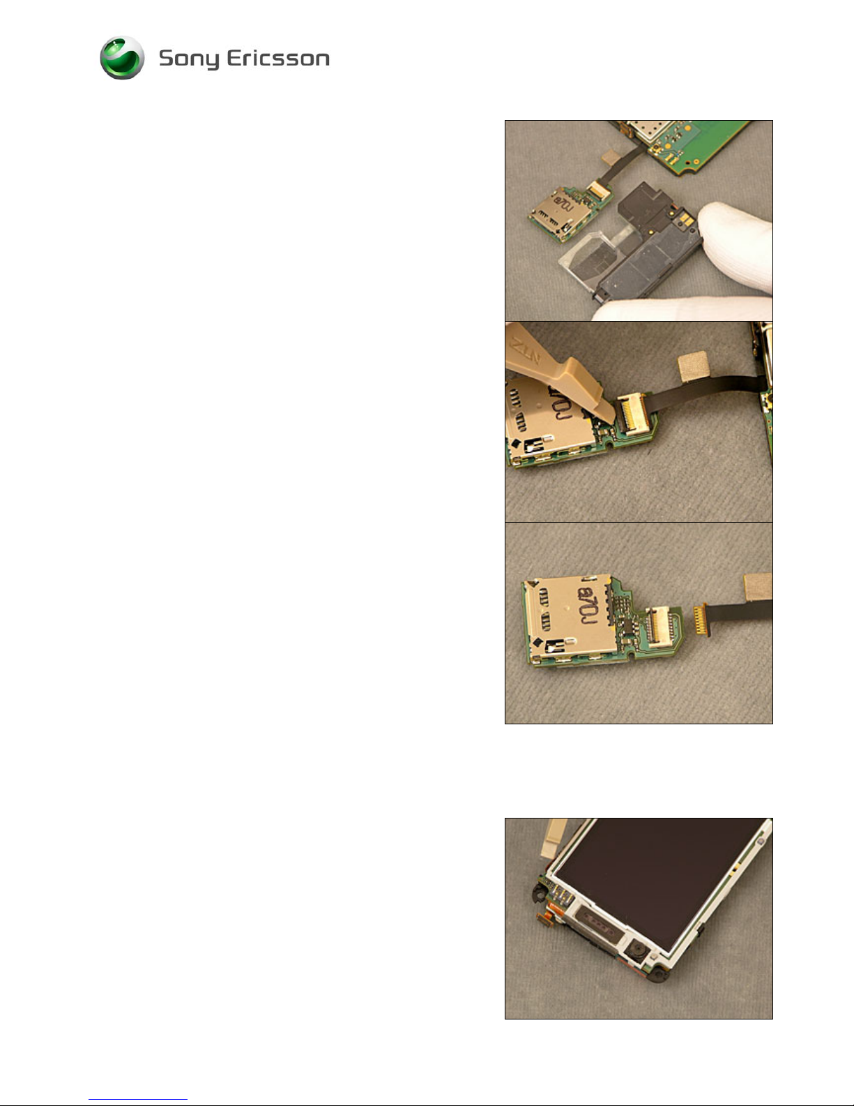
Remove the Speaker box
Open the latch on the Sub PBA M2/SIM
Remove the Sub PBA M2/SIM
2.1.7 Upper Flex Holder
Unsnap the 2 hooks on the Holder
with the Front opening tool
Company Internal
© Sony Ericsson Mobile Communicat i ons AB
Page 14
Working Instruction, Mechanical
1210-5420 Rev1 14(53)
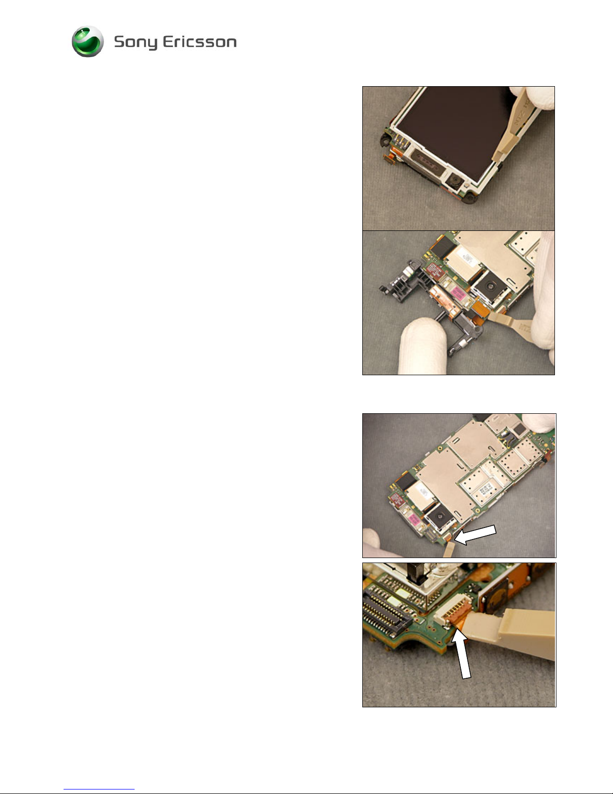
Turn the phone around and lift of the Holder and unsnap the
BtB connector with the front opening tool
2.1.8 Carrier LCD
Open the latch for the volume flex with a front opening tool
Company Internal
© Sony Ericsson Mobile Communicat i ons AB
Page 15
Working Instruction, Mechanical
1210-5420 Rev1 15(53)
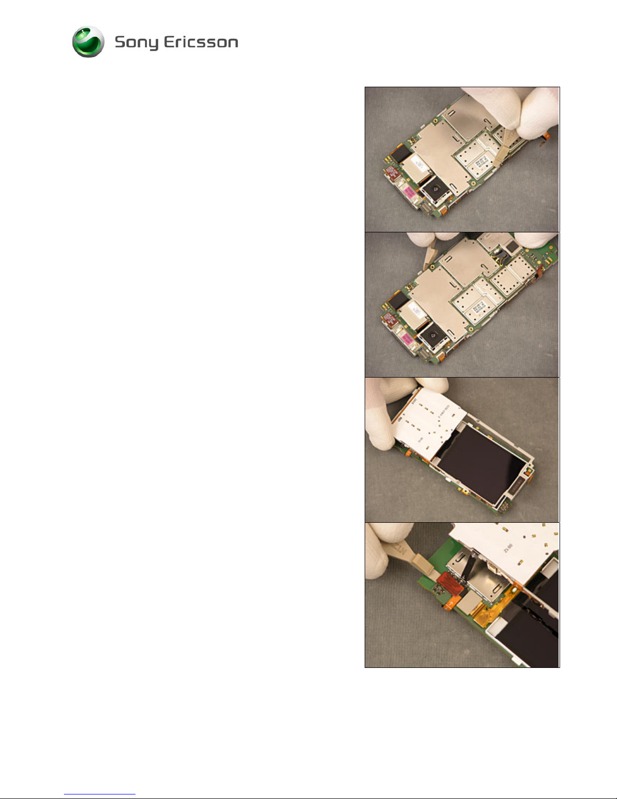
Unsnap the carrier from the PBA
Lift out the Carrier Assy and
unsnap the b2b connector to the LCD Carrier
Company Internal
© Sony Ericsson Mobile Communicat i ons AB
Page 16
Working Instruction, Mechanical
1210-5420 Rev1 16(53)
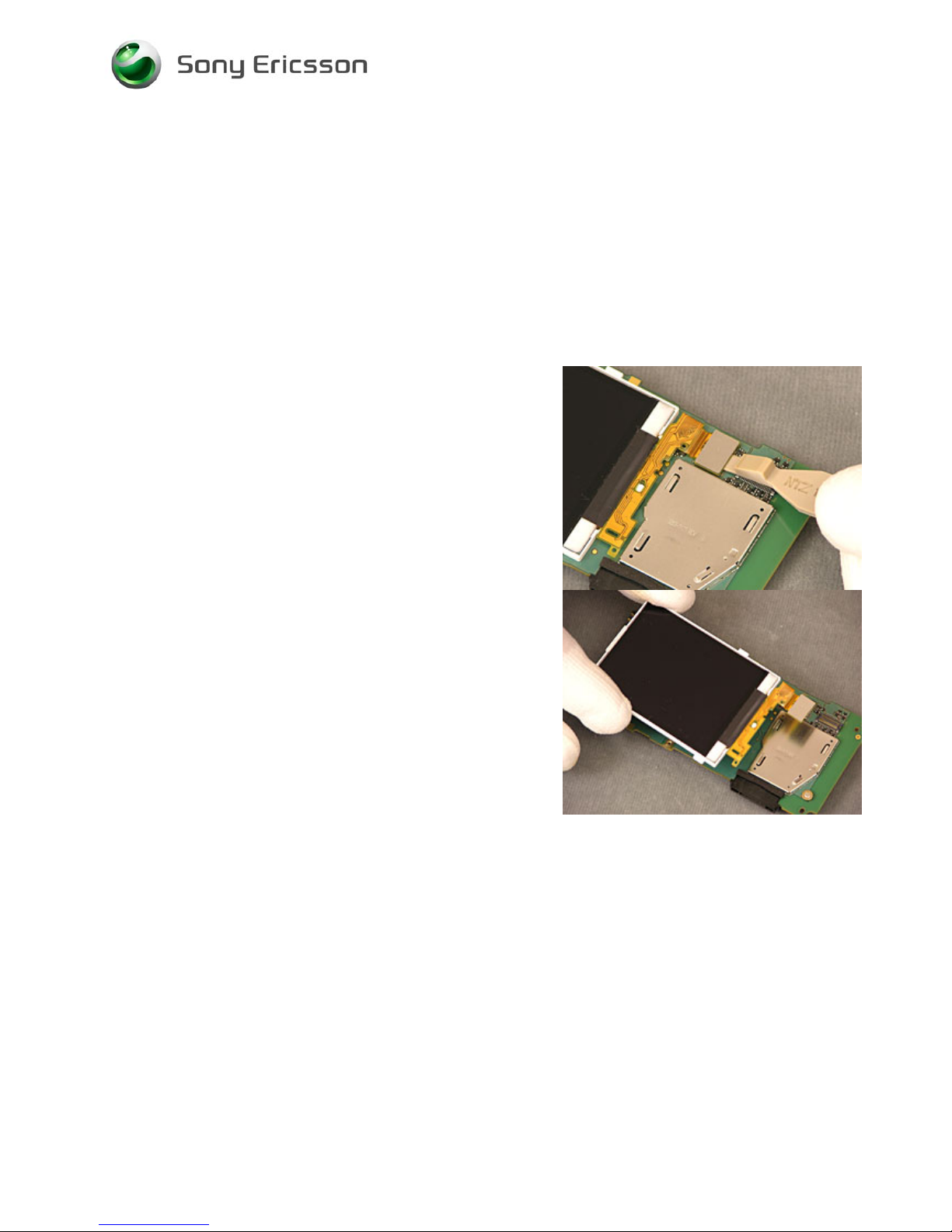
2.1.9 Display
Unsnap the b2b connector to the LCD
Lift out the LCD
Company Internal
© Sony Ericsson Mobile Communicat i ons AB
Page 17

Working Instruction, Mechanical
1210-5420 Rev1 17(53)
3 Replacements
Search for the part to be replaced on the Contents page and go to that instruction to be found in this
Replacements section.
The instruction usually begins by directing you to the Disassembly section with a specification of the
instructions you have to carry out in order to disassemble the phone as far as needed before the
actual replacement.
Go back to this Replacements section and carry out the instruction.
The instruction usually ends by directing you to the Reassembly section with a specification of the
instructions you have to carry out in order to reassemble the phone.
Start
DISASSEMBLY REASSEMBLY
Contents
page
REPLACEMENTS
Done
Company Internal
© Sony Ericsson Mobile Communicat i ons AB
Page 18

Working Instruction, Mechanical
1210-5420 Rev1 18(53)
3.1 Stylus
Follow the 2.1.1 Disassembly instructions!
Prepare the new Battery Lid Assy.
Follow the 4.1.6 Reassembly instructions!
3.2 Battery Cover Assy
Follow the 2.1.1 – 2.1.2 Disassembly instructions!
Prepare the new Battery.
Follow the 4.1.6 Reassembly instructions!
3.3 Battery
Follow the 2.1.1 – 2.1.2 Disassembly instructions!
Prepare the new Stylus.
Follow the 4.1.3 – 4.1.6 Reassembly instructions!
3.4 Camera Cover Assy
Follow the 2.1.1 – 2.1.3 Disassembly instructions!
Prepare the new Camera Cover Assy.
Follow the 4.1.3 – 4.1.6 Reassembly instructions!
3.5 Front Assy
Follow the 2.1.1 – 2.1.4 Disassembly instructions!
Prepare the new Frame Sub Assem Cover.
Follow the 4.1.1 – 4.1.6 Reassembly instructions!
3.6 Frame Assy
Follow the 2.1.1 – 2.1.6 Disassembly instructions!
Prepare the new Front Cover.
Follow the 4.1.1 – 4.1.6 Reassembly instructions!
3.7 Keyboard
Follow the 2.1.1 – 2.1.4Disassembly instructions!
Prepare the new Key Pad
Follow the 4.1.1 – 4.1.6 Reassembly instructions!
Company Internal
© Sony Ericsson Mobile Communicat i ons AB
Page 19

Working Instruction, Mechanical
1210-5420 Rev1 19(53)
3.8 Loudspeaker Box
Follow the 2.1.1 – 2.1.6 Disassembly instructions!
Prepare the new Speaker Box.
Follow the 4.1.4 – 4.1.6 Reassembly instructions!
3.9 M2/SIM Sub PBA
Follow the 2.1.1 – 2.1.6 Disassembly instructions!
Prepare the new M2/SIM Sub PBA.
Follow the 4.1.4 – 4.1.6 Reassembly instructions!
3.10 Upper Flex Holder
Follow the 2.1.1 – 2.1.5 – –2.1.7 Disassembly instructions!
Prepare the new Flash Flex Carrier.
Follow the 4.1.4 – 4.1.6 Reassembly instructions!
3.11 Carrier LCD
Follow the 2.1.1 – 2.1.5 – –2.1.7– 2.1.8 Disassembly instructions!
Prepare the new Flash Flex Carrier.
Follow the 4.1.4 – 4.1.6 Reassembly instructions!
3.12 Display
Follow the 2.1.1 – 2.1.5 – –2.1.7– 2.1.9 Disassembly instructions!
Prepare the new Flash Flex Carrier.
Follow the 4.1.4 – 4.1.6 Reassembly instructions!
3.13 Gasket Loudspeaker
REMOVAL
Follow the 2.1.1 – 2.1.2 Disassembly instructions!
Use a Dentist Hook to remove the Loudspeaker Gasket
Company Internal
© Sony Ericsson Mobile Communicat i ons AB
Page 20

Working Instruction, Mechanical
1210-5420 Rev1 20(53)
INSTALLATION
Use your fingers to position the Loudspeaker Gasket.
Follow the 4.1.7 – 4.1.9 Reassembly instructions!
3.14 Gasket Camera
REMOVAL
Follow the 2.1.3 Disassembly instructions!
Use a Dentist Hook to remove the gasket
INSTALLATION
Use a pair of tweezers to position the Gasket.
Follow the 4.1.9 Reassembly instructions!
Company Internal
© Sony Ericsson Mobile Communicat i ons AB
Page 21

1210-5420 Rev1
Company Internal
© Sony Ericsson Mobile Communicat i ons AB
21(53)
Working Instruction, Mechanical
3.15 Gasket Flash
REMOVAL
Follow the 2.1.3 Disassembly instructions!
Use a Dentist Hook to remove the gasket
INSTALLATION
Use a pair of tweezers to position the Gasket.
Follow the 4.1.9 Reassembly instructions!
3.16 Gasket Mic
REMOVAL
Follow the 2.1.4 Disassembly instructions!
Use a Dentist Hook to remove the Gasket
Page 22

Working Instruction, Mechanical
1210-5420 Rev1 22(53)
INSTALLATION
Use a pair of tweezers to apply the Gasket.
Follow the 4.1.7 – 4.1.9 Reassembly instructions!
3.17 Gasket Q-Sif Camera
REMOVAL
Follow the 2.1.1 – 2.1.5 Disassembly instructions!
Use a Dentist Hook to remove the QSIF Gasket
INSTALLATION
Use a pair of tweezers to apply the QSIF Gasket.
Follow the 4.1.7– 4.1.9 Reassembly instructions!
Company Internal
© Sony Ericsson Mobile Communicat i ons AB
Page 23

Working Instruction, Mechanical
1210-5420 Rev1 23(53)
3.18 Light Guide
REMOVAL
Follow the 2.1.5 Disassembly instructions!
Use a Dentist hook to remove the Light Guide.
INSTALLATION
Use your fingers to position the Light Guide.
Follow the 4.1.6 – 4.1.9 Reassembly instructions!
3.19 Key On/Off
REMOVAL
Follow the 2.1.5 Disassembly instructions!
Use Tweezers and your finger to remove the Key.
Company Internal
© Sony Ericsson Mobile Communicat i ons AB
Page 24

Working Instruction, Mechanical
1210-5420 Rev1 24(53)
INSTALLATION
Use Tweezers insert the Key
Follow the 4.1.6 – 4.1.9 Reassembly instructions!
3.20 Key Hold
REMOVAL
Follow the 2.1.5 Disassembly instructions!
Use Tweezers and your fingersto remove the Key
INSTALLATION
Use Tweezers and your fingers to insert the Key
Follow the 4.1.6 – 4.1.9 Reassembly instructions!
Company Internal
© Sony Ericsson Mobile Communicat i ons AB
Page 25

Working Instruction, Mechanical
1210-5420 Rev1 25(53)
3.21 Key Camera
REMOVAL
Follow the 2.1.5 Disassembly instructions!
Use Tweezers and your fingers to remove the Key
INSTALLATION
Use Tweezers and your fingers to insert the Key
Follow the 4.1.6 – 4.1.9 Reassembly instructions!
3.22 Key Volume
REMOVAL
Follow the 2.1.1 – 2.1.4 Disassembly instructions!
Use Tweezers to remove the Key
Company Internal
© Sony Ericsson Mobile Communicat i ons AB
Page 26

Working Instruction, Mechanical
1210-5420 Rev1 26(53)
INSTALLATION
Use Tweezers and your fingers to insert the Key
Follow the 4.1.6 – 4.1.9 Reassembly instructions!
3.23 Antenna Main Flex
REMOVAL
Follow the 2.1.1 – 2.1.6 Disassembly instructions!
Use a tweezers to remove the Antenna Flex
INSTALLATION
Use the guiding pin on the speaker box to align the antenna
flex.
Follow the 4.1.4 – 4.1.9 Reassembly instructions!
Company Internal
© Sony Ericsson Mobile Communicat i ons AB
Page 27

Working Instruction, Mechanical
1210-5420 Rev1 27(53)
Turn the speaker box around and roll out the antenna flex
Make sure the is no air bubbles on the new flex
3.24 Vibrator
REMOVAL
Follow the 2.1.1 – 2.1.5––2.1.7 Disassembly instructions!
Remove the vibrator with a dentist hook.
Company Internal
© Sony Ericsson Mobile Communicat i ons AB
Page 28

Working Instruction, Mechanical
1210-5420 Rev1 28(53)
INSTALLATION
Use your fingers to insert the new vibrator.
Follow the 4.1.3 – 4.1.9 Reassembly instructions!
3.25 Flash Flex Assy
REMOVAL
Follow the 2.1.1 –2.1.6––2.1.8 Disassembly instructions!
Use a Dentist hook to lift the flex at the Vibrator contact
area.
Fold down the flex.
Company Internal
© Sony Ericsson Mobile Communicat i ons AB
Page 29

Working Instruction, Mechanical
1210-5420 Rev1 29(53)
Turn the carrier around.
Release the flash cooling plate from the carrier and lift out
the flex.
INSTALLATION
Use your fingers and the Flex Film Assembly Tool to pre
bend the flex at the markings.
Follow the 4.1.3 – 4.1.9 Assembly instructions!
Company Internal
© Sony Ericsson Mobile Communicat i ons AB
Page 30

Working Instruction, Mechanical
1210-5420 Rev1 30(53)
Insert the cooling plate in the slot
Push in the BtB bend in the pocket
Turn the Holder around
Push in the vibrator connector part in the slot
Company Internal
© Sony Ericsson Mobile Communicat i ons AB
Page 31

Working Instruction, Mechanical
1210-5420 Rev1 31(53)
Use the guiding pins to align the flex and
press it in place with your fingers
Follow the 4.1.3 – 4.1.9 Assembly instructions!
3.26 Ear speker
REMOVAL
Follow the 2.1.1 – 2.1.5––2.1.7 Disassembly instructions!
Remove the ear speaker with a your fingers or an Dentist
hook.
INSTALLATION
Use your fingers to install the new earspeaker
Follow the 4.1.3 – 4.1.9 Reassembly instructions!
Company Internal
© Sony Ericsson Mobile Communicat i ons AB
Page 32

Working Instruction, Mechanical
1210-5420 Rev1 32(53)
3.27 Gasket ESD Top
REMOVAL
Follow the 2.1.1 – 2.1.8 Disassembly instructions!
Remove the gasket with a Dentist hook.
INSTALLATION
Use a pair of tweezers to install the new gasket
Follow the 4.1.3 – 4.1.9 Reassembly instructions!
Company Internal
© Sony Ericsson Mobile Communicat i ons AB
Page 33

Working Instruction, Mechanical
1210-5420 Rev1 33(53)
3.28 Volume Flex Assy
REMOVAL
Follow the 2.1.7 Disassembly instructions!
Remove the flex with a Dentist hook.
INSTALLATION
Pre bend the flex and use the guiding pins to apply it
correctly.
Follow the 4.1.3 – 4.1.9 Reassembly instructions!
Company Internal
© Sony Ericsson Mobile Communicat i ons AB
Page 34

Working Instruction, Mechanical
1210-5420 Rev1 34(53)
3.29 Grounding Cushions
REMOVAL
Follow the 2.1.5 Disassembly instructions!
Remove the Grounding Cushions with a pair of tweezers
INSTALLATION
Use pair of tweezers to install the new Grounding Cushions
Follow the 2.1.5 – 2.1.9 Reassembly instructions!
Company Internal
© Sony Ericsson Mobile Communicat i ons AB
Page 35

Working Instruction, Mechanical
1210-5420 Rev1 35(53)
3.30 Camera 5 MPixel
REMOVAL
Follow the 2.1.1 – 2.1.5 ––2.1.8 Disassembly instructions!
Use a front opening tool to remove the Camera
INSTALLATION
Apply the adhesive and pre bend the flex
Company Internal
© Sony Ericsson Mobile Communicat i ons AB
Page 36

Working Instruction, Mechanical
1210-5420 Rev1 36(53)
Use your fingers to place the Camera in the corner off the
recess.
Follow the 4.1.5 – 4.1.9 Reassembly instructions!
Use your fingers to snap on the BtB connector
3.31 Flex Keyboard Assy
REMOVAL
Follow the 2.1.1 – 2.1.9 Disassembly instructions!
Use a dentist hook and your fingers to remove the Dome
Sheet Flex
Company Internal
© Sony Ericsson Mobile Communicat i ons AB
Page 37

Working Instruction, Mechanical
1210-5420 Rev1 37(53)
INSTALLATION
Clean up the surface from adhesive residues
And use the guiding pins to align the new Dome Sheet Flex
Roll on the flex to avoid air bubbles
Follow the 4.1.1 – 4.1.9 Reassembly instructions!
3.32 Mic Gasket
REMOVAL
Follow the 2.1.1 – 2.1.9 Disassembly instructions!
Use a dentist hook to remove the gasket
INSTALLATION
Use a pair of tweezers to place the gasket
Make shore the gasket is in place by pushing it down with
your fingers
Follow the 4.1.1 – 4.1.9 Reassembly instructions!
Company Internal
© Sony Ericsson Mobile Communicat i ons AB
Page 38

Working Instruction, Mechanical
1210-5420 Rev1 38(53)
3.33 BtB Gasket
REMOVAL
Follow the 2.1.1 – 2.1.9 Disassembly instructions!
Use a Dentist Hook to remove the Gasket
Clean up the surface from adhesive residues
INSTALLATION
Use a pair of tweezers to place the gasket within the
markings
Follow the 4.1.1 – 4.1.9 Reassembly instructions!
Company Internal
© Sony Ericsson Mobile Communicat i ons AB
Page 39

Working Instruction, Mechanical
1210-5420 Rev1 39(53)
3.34 Camera Module QSIF
REMOVAL
Follow the 2.1.1 – 2.1.6––2.1.8–2.1.9 Disassembly
instructions!
Use a Front Opening Tool to disconnect the Camera
INSTALLATION
Use your fingers to apply the new camera
Follow the 4.1.1 – 4.1.9 Reassembly instructions!
3.35 I/O Connector/Dust Gasket
REMOVAL
Follow the 2.1.1 –2.1.9 Disassembly instructions!
Use Your fingers to remove the Connector/Gasket
Company Internal
© Sony Ericsson Mobile Communicat i ons AB
Page 40

Working Instruction, Mechanical
1210-5420 Rev1 40(53)
INSTALLATION
Use your fingers to insert the new Connector/Gasket
Follow the 4.1.1 – 4.1.9 Reassembly instructions!
3.36 Thread Inserts
REMOVAL
Follow the 2.1.1 – 2.1.9 Disassembly instructions!
Use a Philip screwdriver to press out the inserts
Company Internal
© Sony Ericsson Mobile Communicat i ons AB
Page 41

Working Instruction, Mechanical
1210-5420 Rev1 41(53)
INSTALLATION
Use a pair of players to inert the new inserts
Follow the 4.1.1 – 4.1.9 Reassembly instructions!
3.37 Shield Cans x 5
REMOVAL
Follow the 2.1.1 – 2.1.9 Disassembly instructions!
Use a screwdriver to release the shield cans
Company Internal
© Sony Ericsson Mobile Communicat i ons AB
Page 42

Working Instruction, Mechanical
1210-5420 Rev1 42(53)
INSTALLATION
Use your finger to inert the new shield cans
Follow the 4.1.1 – 4.1.9 Reassembly instructions!
3.38 Liquid Intrusion Indicator
REMOVAL
Follow the 2.1.1 – 2.1.7 Disassembly instructions!
Use a dentist hook to remove the label
INSTALLATION
Use a pair of tweezers to apply the new label
Follow the 4.1.4– 4.1.9 Reassembly instructions!
Company Internal
© Sony Ericsson Mobile Communicat i ons AB
Page 43

Working Instruction, Mechanical
1210-5420 Rev1 43(53)
3.39 Cushion 1,05 mm
REMOVAL
Follow the 2.1.1 – 2.1.9 Disassembly instructions!
Use a Dentist hook to remove the Cushion
INSTALLATION
Use a pair of tweezers to apply the new Cushion
Follow the 4.1.1 – 4.1.9 Reassembly instructions!
3.40 ISP Cushion
REMOVAL
Follow the 2.1.1 – 2.1.9 Disassembly instructions!
Use a Dentist hook or a pair of tweezers to remove the
Cushion
INSTALLATION
Use your fingers to apply the new Cushion
Follow the 4.1.1 – 4.1.9 Reassembly instructions!
Company Internal
© Sony Ericsson Mobile Communicat i ons AB
Page 44

Working Instruction, Mechanical
1210-5420 Rev1 44(53)
3.41 KRH Label
Follow the 2.1.1 Disassembly instructions!
• Read the old label and/or write the information into the
“Label make” program before removal
• Note the position of the label before removal
• Heat up the label by using hot air, if needed
• Carefully remove the label without causing scratches
• If there still are residues, clean the surface with isopropyl
alcohol
• Check that the proper label format is loaded in the Zebra
printer
• Write a new label by using the program “Label make”
and check that the printing is OK
• Take the new label and place it onto the frame as in the
adjacent picture
O
NE LABEL ONLY IS ALLOWED!
Follow the 4.1.6 Reassembly instructions!
4 Reassembly
After replacing a part being listed in Replacements, the instruction of that section usually ends by
directing you to this Reassembly section with a specification of the instructions you have to carry out
in order to reassemble the phone.
Company Internal
© Sony Ericsson Mobile Communicat i ons AB
Page 45

Working Instruction, Mechanical
1210-5420 Rev1 45(53)
Start
DISASSEMBLY
REASSEMBLY
Contents
page
REPLACEMENTS
Done
Company Internal
© Sony Ericsson Mobile Communicat i ons AB
Page 46

Working Instruction, Mechanical
1210-5420 Rev1 46(53)
4.1 Overview
The reassembly is done in the following order:
1. PBA
2. Display
3. LCD Carrier
4. Upper Flex Holder
5. M2/SIM Sub PBA
6. Loudspeaker Box
7. Frame Assy
8. Front Assy and Keyboard
9. Camera Cover Assy
10. Stylus
11. Battery Cover Assy (a) & Battery (b)
Company Internal
© Sony Ericsson Mobile Communicat i ons AB
Page 47

Working Instruction, Mechanical
1210-5420 Rev1 47(53)
4.1.1 Display
Use your fingers to install the LCD BtB connector
Use your fingers to position Frame LCD
4.1.2 Carrier LCD
Use your fingers to install the BtB connector
Company Internal
© Sony Ericsson Mobile Communicat i ons AB
Page 48

Working Instruction, Mechanical
1210-5420 Rev1 48(53)
Use your fingers to position the Carrier and snap it on
Secure the volume flex
4.1.3 Upper Flex Holder
Use your fingers to position the BtB connector
Use your fingers to snap on the Holder
Company Internal
© Sony Ericsson Mobile Communicat i ons AB
Page 49

Working Instruction, Mechanical
1210-5420 Rev1 49(53)
4.1.4 M2/SIM Sub PBA and Loudspeaker box
Put in the flex in to the M2/SIM BPA and lock the latch with
a front opening tool
Snap the M2/SIM BPA in to the speaker box
Turn the speakerbox around an press it on to the PBA
Company Internal
© Sony Ericsson Mobile Communicat i ons AB
Page 50

Working Instruction, Mechanical
1210-5420 Rev1 50(53)
4.1.5 Frame Assy
Place the On/Off dome flex in the key slot
Use your fingers to place the Core Unit in the frame
4.1.6 Front Assy
Make sure the grounding cushions and the light guide are in
place
Use your fingers to snap on the Front
Company Internal
© Sony Ericsson Mobile Communicat i ons AB
Page 51

Working Instruction, Mechanical
1210-5420 Rev1 51(53)
Take new screws and use the Torx bit No 5 for the small
screws and tightened them to with the torque 11 Ncm
Place the strap holder on the lower right screw.
Take new screws and use the Torx bit No 6 for the large
screws and tightened them to with the torque 16 Nc
m
4.1.7 Camera Cover
Use your fingers to snap on the cover
Company Internal
© Sony Ericsson Mobile Communicat i ons AB
Page 52

Working Instruction, Mechanical
1210-5420 Rev1 52(53)
4.1.8 Battery and battery cover Assy
Use your fingers to insert the Battery and the battery lid
4.1.9 Stylos
Use your fingers to insert the Stylus
Company Internal
© Sony Ericsson Mobile Communicat i ons AB
Page 53

Working Instruction, Mechanical
1210-5420 Rev1 53(53)
5 Revision history
Rev. Date Changes / Comments
1 2008-04-24 Initial release
Company Internal
© Sony Ericsson Mobile Communicat i ons AB
 Loading...