

Sony ZS-X3CP Service manual

ZS-X3CP
SERVICE MANUAL
Ver 1.0 2002.02
SPECIFICATIONS
US Model
Canadian Model
Model Name Using Similar Mechanism NEW
CD Mechanism Type KSM-900AAA
Optical Pick-up Name KSS-900A
AUDIO POWER SPECIFICATIONS General
(US model only)
POWER OUTPUT AND TOTAL HARMONIC
DISTORTION
With 3.2-ohm loads, both channels driven from
150 - 10,000 Hz; rated 1.8 W per channelminimum RMS power, with no more than 10 %
total harmonic distortion in AC operation.
Other Specifications
CD player section
System
Compact disc digital audio system
Laser diode properties
Material: GaAlAs
Wave length: 780 nm
Emission duration: Continuous
Laser output: Less than 44.6 µW
(This output is the value measured at a distance of about
200 mm from the objective lens surface on the optical
pick-up block with 7 mm aperture.)
Spindle speed
200 r/min (rpm) to 500 r/min (rpm) (CLV)
Number of channels
2
Frequency response
20 - 20 000 Hz +1/–2 dB
Wow and flutter
Below measurable limit
Radio section
Frequency range
FM: 87.5 - 108 MHz
AM: 530 - 1 710 kHz
Antennas
FM: Telescopic antenna
AM: Built-in ferrite bar antenna
Speaker
Full range: 10 cm (4 in.) dia.,
3.2 Ω, cone type (2)
Outputs
Headphones jack (stereo minijack)
For 16 - 68 Ω impedance headphones
Power output
2.3 W + 2.3 W (at 3.2 Ω, 10 % harmonic
distortion)
Power requirements
DC IN 9V jack accepts:
Supplied AC power adaptor for use with 120 V AC,
60 Hz
9 V DC, 6 size D (R20) batteries
Battery life
For CD playback:
Sony R20P: approx. 7.5 h
Sony alkaline LR20: approx. 14 h
Dimensions
Approx. 430 172 287.5 mm (w/h/d)
(17 ×
Mass
Approx. 4.6 kg (7 lb. 11 oz) (incl. batteries)
Supplied accessories
AC power adaptor (1)
Design and specifications are subject to change without
notice.
6 7⁄8 × 11 3⁄
8
inches) (incl. projecting parts)
9-873-537-01 Sony Corporation
2002B0500-1 Personal Audio Company
C 2002.02 Published by Sony Engineering Corporation
PERSONAL AUDIO SYSTEM

ZS-X3CP
TABLE OF CONTENTS
1. SERVICING NOTES.............................................. 4
2. GENERAL .................................................................. 5
3. DISASSEMBLY
3-1. Disassembly Flow ........................................................... 7
3-2. Cabinet Lower, Telescopic Antenna (ANT1) ................. 8
3-3. Main Chassis Section ...................................................... 9
3-4. AUDIO Board, BATTERY Board .................................. 9
3-5. TUNER Board, CONTROL Board................................. 10
3-6. CDMP3 Board................................................................. 11
3-7. Optical Pick-up Section .................................................. 11
3-8. Sled Motor Assy (780CP) (M702).................................. 12
3-9. Optical Pick-up (KSS-900A) .......................................... 12
3-10. Cabinet Front Section ..................................................... 13
3-11. Speaker Unit (L) (SP1), Speaker Unit (R) (SP2) ........... 13
3-12. Lid CD............................................................................. 14
4. ELECTRICAL ADJUSTMENTS
Tuner Section ................................................................. 15
CD Section ..................................................................... 17
5. DIAGRAMS
5-1. Block Diagram – CD Section – .................................... 18
5-2. Block Diagram – TUNER Section – ............................ 19
5-3. Block Diagram – MAIN Section – ............................... 20
5-4. Note for Printed Wiring Boards and
Schematic Diagrams ....................................................... 21
5-5. Printed Wiring Boards – CD Section – ........................ 23
5-6. Schematic Diagram – CD Section (1/2) – .................... 24
5-7. Schematic Diagram – CD Section (2/2) – .................... 25
5-8. Printed Wiring Board – TUNER Section – .................. 26
5-9. Schematic Diagram – TUNER Section – ..................... 27
5-10. Printed Wiring Boards – CONTROL Section – ........... 28
5-11. Schematic Diag ram – CONTROL Section –................ 29
5-12. Printed Wiring Boards
– AUDIO/PO WER Section – ......................................... 30
5-13. Schematic Diag ram – AUDIO/POWER Section –....... 31
5-14. IC Pin Function Description .......................................... 33
6. EXPLODED VIEWS
6-1. Cabinet Lower Section.................................................... 37
6-2. Cabinet Front Section ..................................................... 38
6-3. Cabinet Upper Section-1................................................. 39
6-4. Cabinet Upper Section-2................................................. 40
6-5. Cabinet Upper Section-3................................................. 41
6-6. Main Chassis Section ...................................................... 42
6-7. Optical Pick-up Section (KSM-900AAA) ..................... 43
7. ELECTRICAL PARTS LIST .............................. 44
2
ZS-X3CP
About CD-Rs/CD-RWs and MP3 files
This player can play CD-Rs/CD-RWs recorded in the CDDA format* and MP3 files recorded in the CD-ROM
format, but playback capability may vary depending on the
quality of the disc and the condition of the recording
device.
* CD-DA is the abbreviation for Compact Disc Digital Audio. It is
a recording standard used for Audio CDs.
Notes on chip component replacement
• Never reuse a disconnected chip component.
• Notice that the minus side of a tantalum capacitor may be dam-
aged by heat.
Flexible Circuit Board Repairing
• Keep the temperature of the soldering iron around 270 ˚C during repairing.
• Do not touch the soldering iron on the same conductor of the
circuit board (within 3 times).
• Be careful not to apply force on the conductor when soldering
or unsoldering.
SAFETY CHECK-OUT
After correcting the original service problem, perform the following safety check before releasing the set to the customer:
Check the antenna terminals, metal trim, “metallized” knobs,
screws, and all other exposed metal parts for AC leakage.
Check leakage as described below.
LEAKAGE TEST
The AC leakage from any exposed metal part to earth ground and
from all exposed metal parts to any exposed metal part having a
return to chassis, must not exceed 0.5 mA (500 microamperes).
Leakage current can be measured by any one of three methods.
1. A commercial leakage tester , such as the Simpson 229 or RCA
WT -540A. Follo w the manufacturers’ instructions to use these
instruments.
2. A battery-operated AC milliammeter. The Data Precision 245
digital multimeter is suitable for this job.
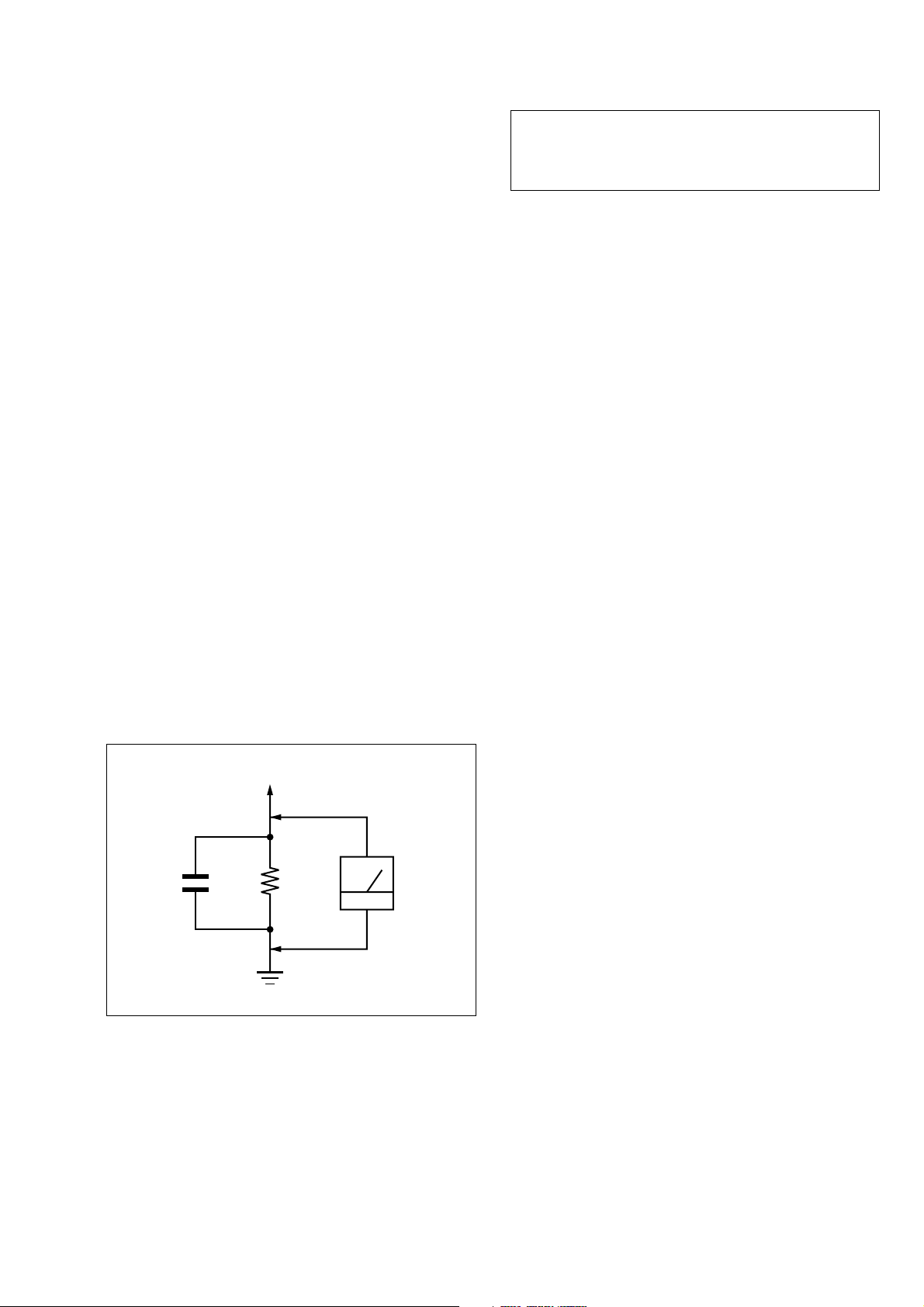
3. Measuring the voltage drop across a resistor by means of a
VOM or battery-operated AC voltmeter. The “limit” indication is 0.75 V, so analog meters must have an accurate lowvoltage scale. The Simpson 250 and Sanwa SH-63Trd are examples of a passive VOM that is suitable. Nearly all battery
operated digital multimeters that have a 2 V A C range are suitable. (See Fig. A)
CAUTION
Use of controls or adjustments or performance of procedures
other than those specified herein may result in hazardous radiation exposure.
To Exposed Metal
Parts on Set
1.5 k
0.15 µF
Fig. A. Using an AC voltmeter to check AC leakage.
SAFETY-RELATED COMPONENT WARNING!!
COMPONENTS IDENTIFIED BY MARK 0 OR DOTTED
LINE WITH MARK 0 ON THE SCHEMATIC DIA GRAMS
AND IN THE PARTS LIST ARE CRITICAL TO SAFE
OPERATION. REPLACE THESE COMPONENTS WITH
SONY PARTS WHOSE PART NUMBERS APPEAR AS
SHOWN IN THIS MANUAL OR IN SUPPLEMENTS PUBLISHED BY SONY.
Ω
Earth Ground
AC
voltmeter
(0.75 V)
ATTENTION AU COMPOSANT AYANT RAPPORT
À LA SÉCURITÉ!
LES COMPOSANTS IDENTIFIÉS P AR UNE MARQUE 0
SUR LES DIAGRAMMES SCHÉMATIQUES ET LA LISTE
DES PIÈCES SONT CRITIQUES POUR LA SÉCURITÉ
DE FONCTIONNEMENT. NE REMPLACER CES COMPOSANTS QUE PAR DES PIÈCES SONY DONT LES
NUMÉROS SONT DONNÉS DANS CE MANUEL OU
DANS LES SUPPLÉMENTS PUBLIÉS PAR SONY.
3
ZS-X3CP
SECTION 1
SERVICING NOTES
NOTES ON HANDLING THE OPTICAL PICK-UP
BLOCK OR BASE UNIT
The laser diode in the optical pick-up block may suffer electrostatic break-down because of the potential difference generated
by the charged electrostatic load, etc. on clothing and the human
body.
During repair, pay attention to electrostatic break-down and also
use the procedure in the printed matter which is included in the
repair parts.
The flexible board is easily damaged and should be handled with
care.
NOTES ON LASER DIODE EMISSION CHECK
The laser beam on this model is concentrated so as to be focused
on the disc reflective surface by the objective lens in the optical
pick-up block. Therefore, when checking the laser diode emission, observe from more than 30 cm away from the objectiv e lens.
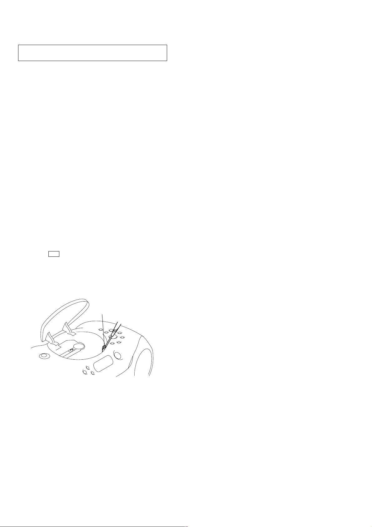
LASER DIODE AND FOCUS SEARCH OPERATION
CHECK
During normal operation of the equipment, emission of the laser
diode is prohibited unless the upper lid is closed while turning ON
the S701. (push switch type)
The following checking method for the laser diode is operable.
• Method
Emission of the laser diode is visually checked.
1. Open the upper lid.
2. Push the S701 as shown in Fig.1.
Note: Do not push the detection lever strongly, or it may be bent or dam-
aged.
3. Press the u button.
4. Check the object lens for confirming normal emission of the
laser diode. If not emitting, there is a trouble in the automatic
power control circuit or the optical pick-up.
In this operation, the object lens will move up and down 2
times along with inward motion for the focus search.
S701
Fig.1 Method to push the S701
4
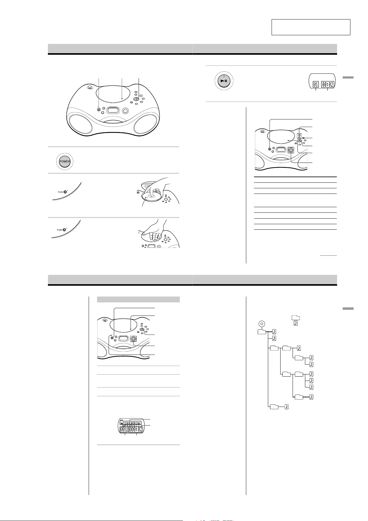
Basic Operations
Playing an audio CD or MP3 files
1
ZS-X3CP
SECTION 2
GENERAL
42, 3
4 Press u.
The player plays all the tracks once.
To play a CD with MP3 files, see
page 6.
Use these buttons for additional operations
This section is extracted from
instruction manual.
Display
Playing
Track
time
number
POWER
VOLUME +, —
Basic Operations
Connect the supplied AC power adaptor (see page 18).
1
2
3
Press POWER to turn on the player.
Press Z PUSH down to open the CD
compartment and place the CD on
the CD compartment until it clicks
into place.
Close the lid of the CD compartment.
4
Playing an audio CD or MP3 files (continued)
Playing a CD with MP3 files
Note
Before playing a file, this
player reads all file and
folder information on the
CD. Depending on the
file structure, it may take
more than a minute to
read them. During this
time, Reading is
displayed.
Tip
You can use the buttons
mentioned in the table on
page 5 for additional
operations in the same
way as when playing an
audio CD.
1
Press POWER to turn on the player.
2
Press Z PUSH to open the CD compartment and place
the CD on the CD compartment (see page 4) .
3
Close the lid of the CD compartment.
4
Press u.
The player plays all MP3 files on the CD.
When you play a CD with MP3 files, the MP3
indicator lights up.
Track number
With the label side up
POWER
Z PUSH
u
Jog lever
MP3 indicator
Folder name
File name
Playing time
Tip
Playback starts from the
track you last stopped
playing (Resume play).
During stop, the track
number to be played are
displayed.
To cancel the resume play
to start play from the
beginning of the first track,
press x in stop mode.
Notes
¥ A folder that does not
include an MP3 file is
skipped.
¥ Maximum number of
folders: 255
Maximum number of files:
255
¥ Folder names and file
names can be displayed
with up to 64 characters.
¥ The characters A - Z, a - z,
0 - 9, and _ can be
displayed on this player.
Other characters are
displayed as *.
¥ This player conforms to
Version 1.1 of the ID3 tag
format. If the file has the
ID3 tag information, song
title, artist name and
album name can be
displayed.
x
u
Z PUSH
Jog lever
To Do this
adjust the volume Press VOLUME +*, —.
stop playback Press x.
pause playback Press u*.
go to the next track Push jog lever toward >.
go back to the previous track Push jog lever toward ..
remove the CD** Press Z PUSH.
turn on/off the player Press POWER.
* The button has a tactile dot.
**Once you open the CD compartment, the track to start play will
change to the beginning of the first track.
Example of folder structure and playing
order
The playing order of the folders and files is as follows:
CD-R
CD-RW
1
6
1
2
2
Press the button again to
resume play after pause.
Folder
MP3 file
3
3
4
5
0
continued
4
5
6
7
8
9
5
Basic Operations
To select a folder
Push the jog lever toward FLDR + to go forward and
FLDR — to go backward.
To select a file
Push the jog lever toward > to go forward and . to
go backward.
6
7
5
ZS-X3CP
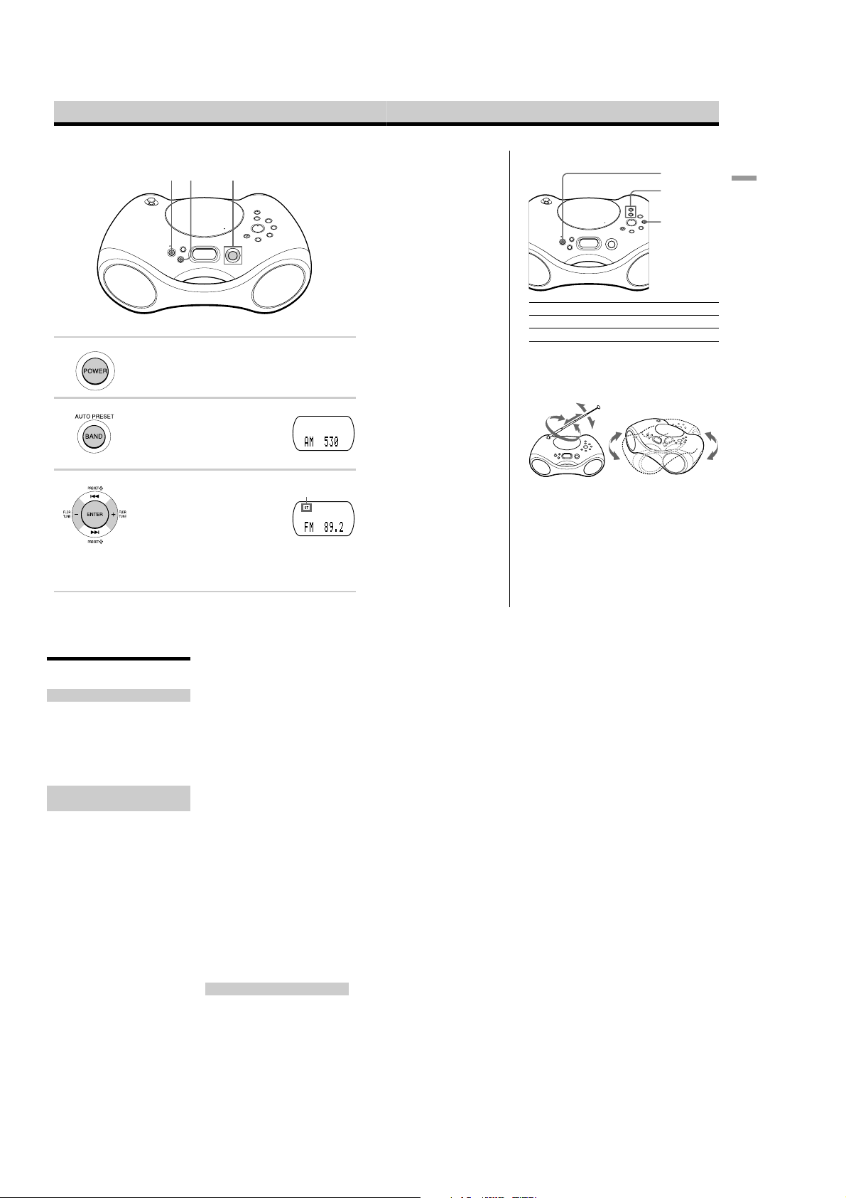
Listening to the radio
132
Connect the supplied AC power adaptor (see page 18).
1 Press POWER to turn on the player.
2 Press BAND¥AUTO PRESET until
3 Push the jog lever toward TUNE + or
8
the band you want appears in the
display.
TUNE — and hold it until the
frequency digits begin to change in
the display.
The player automatically scans the
radio frequencies and stops when it
finds a clear station.
If you cant tune in a station, push
the jog lever toward TUNE + or
TUNE — repeatedly to change the
frequency step by step.
Display
Indicates an FM
stereo broadcast
Tip
If the FM broadcast is
noisy, press MODE until
Mono appears in the
display and radio will play
in monaural.
Use these buttons for additional operations
POWER
VOLUME +, —
MODE
To Press
adjust the volume VOLUME +*, —
turn on/off the radio POWER
*VOLUME + has a tactile dot.
To improve broadcast reception
Reorient the antenna for FM. Reorient the player itself for
AM.
for FM
for AM
Basic Operations
9
About “MP3”
What is the MP3?
MP3 (MPEG 1 Audio Layer-3) is a standard
technology and format for compressing a
sound sequence. The file is compressed to
about 1/10 of its original size. Sounds
outside the range of human hearing are
compressed while the sounds we can hear
are not compressed.
Playable “MP3” files on this
player
You can only play MP3 files recorded by
following requirements.
USABLE MEDIA
CD-Rs and CD-RWs
USABLE DISC FORMAT
You can use ISO 9660 Level 1, Level 2 and
Joliet extension format discs. In some cases,
MP3 files that are recorded in a format other
than these formats may not play normally or
the file and folder names may not be
displayed correctly.
The major specifications of the usable disc
format are as follows:
¥ Maximum directory steps: 8
¥ Usable characters for a file/folder name:
A - Z, a - z, 0 - 9, _ (underscore)
¥ Maximum number of characters for a file
name: 64 including quotation marks and a
3-character extension code
Notes
¥ When naming, be sure to add the file extension
mp3 to the file name.
¥ If you put the extension mp3 to a file other
than an MP3 file, the player cannot recognize
the file properly and will generate random noise
that could damage your speakers.
¥ The file name does not correspond to the ID tag.
THE USABLE NUMBER OF
FOLDERS/FILES
¥ Maximum folder number: 255
¥ Maximum file number: 255
SETTINGS FOR COMPRESSION
SOFTWARE AND WRITING
SOFTWARE
¥ To compress a source for an MP3 file, we
recommend setting the transfer bit rate of
the compression software to 44.1 kHz,
128kbps, and Constant Bit Rate.
¥ To record up to the maximum capacity, set
to the halting of writing.
¥ To record at one time up to the maximum
capacity on media that has nothing
recorded it, set to Disc at Once.
NOTES FOR SAVING FILES ON
THE MEDIA
When the disc is inserted, the player reads
all the files on that disc. If there are many
folders or non-MP3 files on the disc, it may
take a long time for play to begin or for the
next MP3 file to start play.
Do not save unnecessary folders or files
other than MP3 ones in the disc to be used
for MP3 listening.
We recommend that you do not save other
types files or unnecessary folders on a disc
that has MP3 files.
About “ID3 tag”
ID3 tag is a format for adding certain
information (song title, artist name, album
name, etc.) to MP3 files.
This player conforms to Version 1.1 of the
ID3 tag format. If the file has the ID3 tag
information, song title, artist name and
album name can be displayed.
Note
If you use a version other than 1.1, ID3 tag
information will not be displayed correctly.
25
6
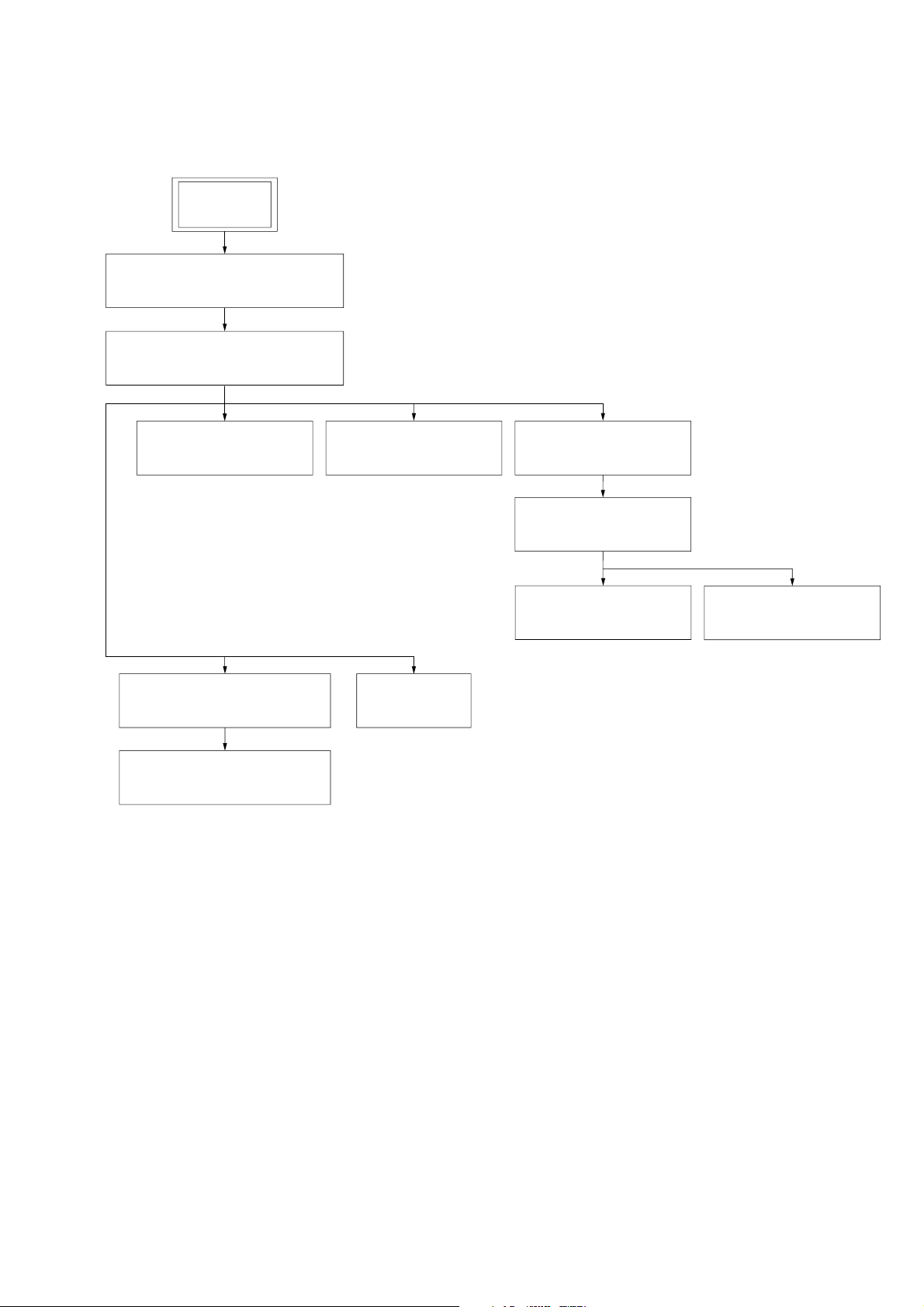
• This set can be disassembled in the order shown below.
3-1. DISASSEMBLY FLOW
SET
3-2. CABINET LOWER,
TELESCOPIC ANTENNA (ANT1)
(Page 8)
3-3. MAIN CHASSIS SECTION
(Page 9)
ZS-X3CP
SECTION 3
DISASSEMBLY
3-4. AUDIO BOARD,
BATTERY BOARD
(Page 9)
3-10.CABINET FRONT SECTION
(Page 13)
3-11.SPEAKER UNIT (L) (SP1),
SPEAKER UNIT (R) (SP2)
(Page 13)
3-5. TUNER BOARD,
CONTROL BOARD
(Page 10)
3-12.LID CD
(Page 14)
3-6. CDMP3 BOARD
(Page 11)
3-7. OPTICAL PICK-UP
SECTION
(Page 11)
3-8. SLED MOTOR ASSY
(780CP) (M702)
(Page 12)
3-9. OPTICAL PICK-UP
(KSS-900A)
(Page 12)
7

ZS-X3CP
g
Note: Follow the disassembly procedure in the numerical order given.
3-2. CABINET LOWER, TELESCOPIC ANTENNA (ANT1)
1
2
screw
(BVTP 3
×
14)
Open the lid CD.
6
cabinet lower
4
five screws
(BVTP3
×
14)
5
screw
(B3
4
five screws
×
(BVTP3
×
8)
14)
4
two screws
(BVTP3
×
14)
3
lid battery
7
telescopic antenna
(ANT1)
!
telescopic antenna
(ANT1)
A
main chassis
Note: Install the telescopic antenna with engagin
the
!
check that the antenna is engaged and
does not move even trying to rotate it
in the direction of arrow
portion to the main chassis, then
A
.
8
ZS-X3CP
r
)
)
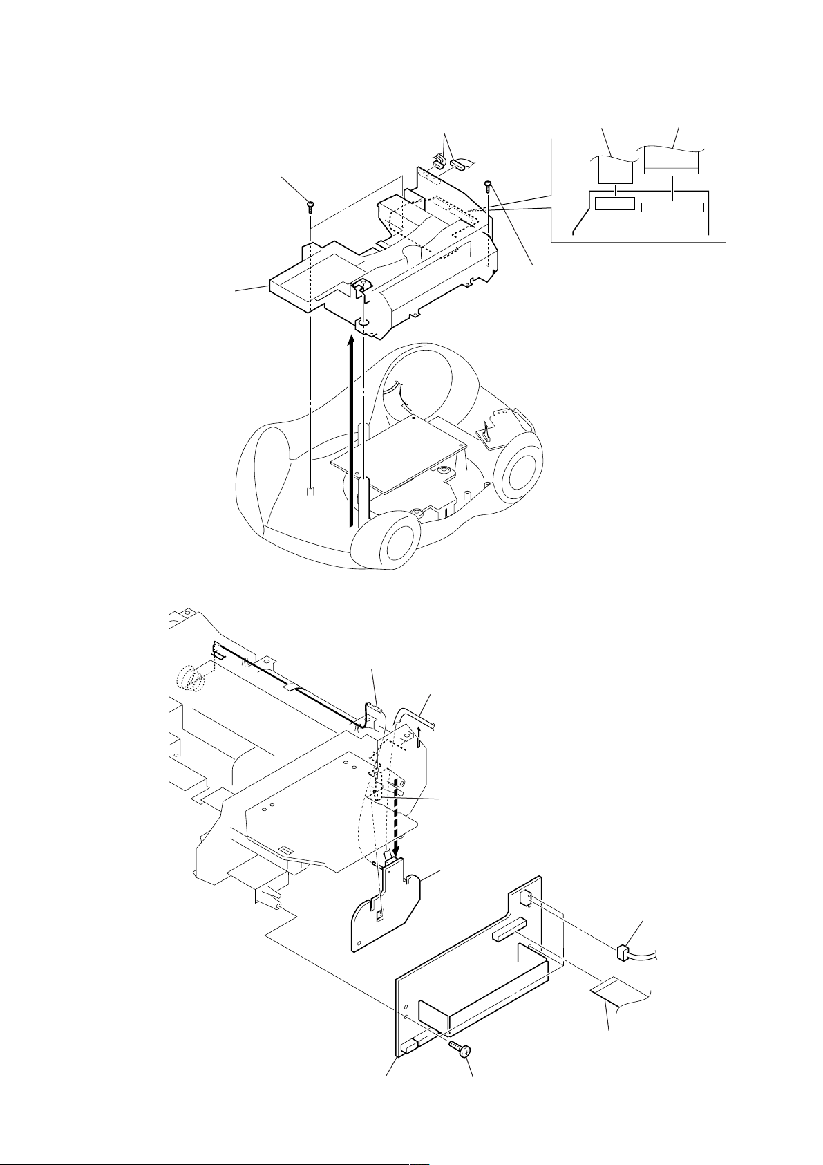
3-3. MAIN CHASSIS SECTION
2
two screws
(BVTP3 × 10)
6
main chassis section
3
1
two connectors
(CN302, CNP303)
4
flat cable (21P)
(CNP801)
2
two screws
(BVTP3 × 10)
5
flat cable (30P
(CNP802)
3-4. AUDIO BOARD, BATTERY BOARD
6
terminal
5
Remove the connector lead wire
from the incision.
7
claw
8
battery board
2
connecto
(CNP901
4
audio board
3
three screws
(BVTP3 × 10)
1
flat cable (18P)
(CNP301)
9
ZS-X3CP
s
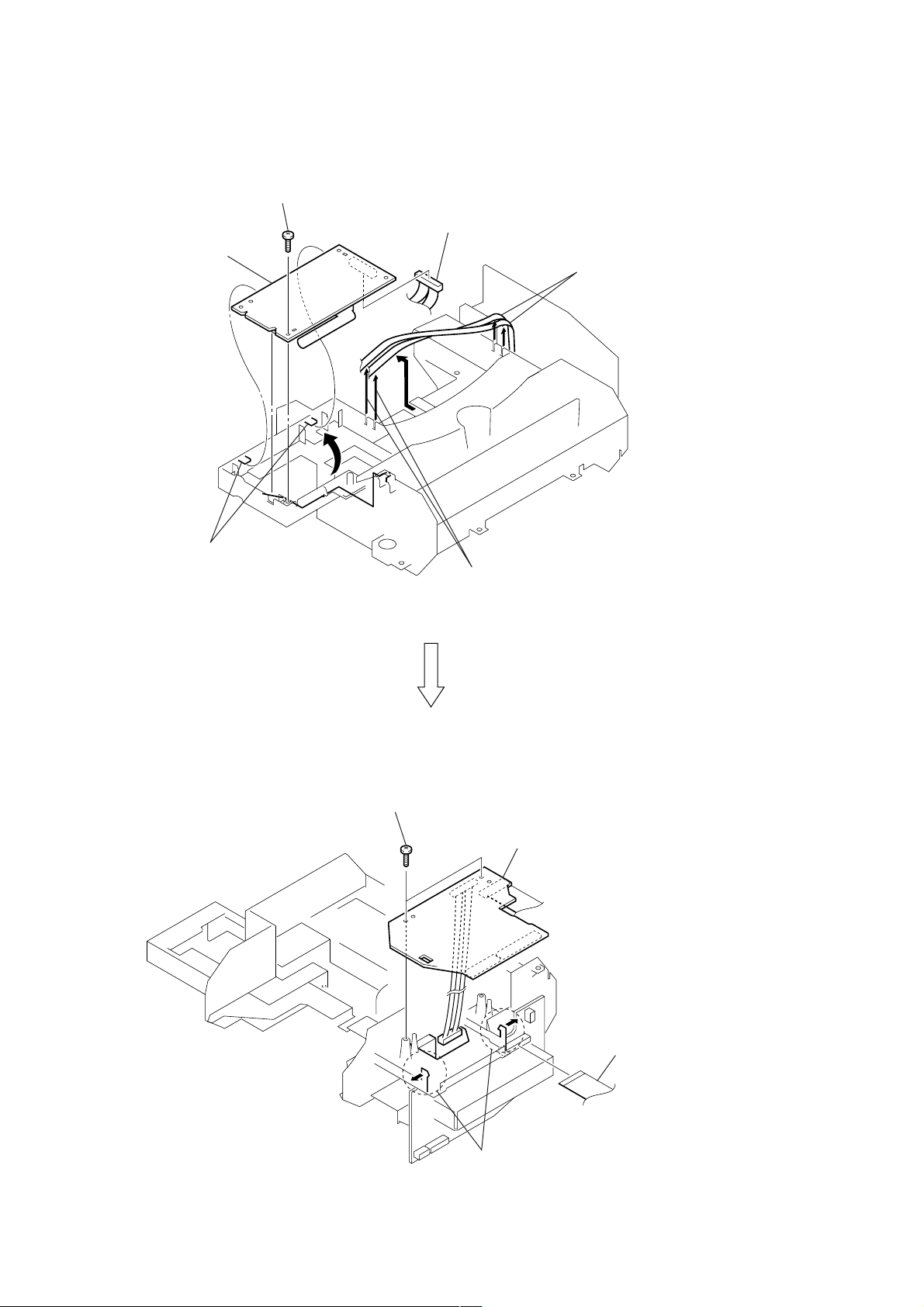
3-5. TUNER BOARD, CONTROL BOARD
1
screw
(BVTP3
×
10)
5
tuner board
2
7
4
connector
(CNP1)
8
Remove the lead wire
from the incision.
3
two convex portions
0
two screws
(BVTP3
×
10)
6
Remove the connector lead wires
from the incision.
qs
control board
10
qa
two claws
9
flat cable (18P)
(CNP301)
3-6. CDMP3 BOARD
r
)
3
flat cable (20P)
(CNP701)
5
CDMP3 board
2
1
three screws
(BTP2.6 × 8)
4
connector
(push (1 key) switch) (S701)
ZS-X3CP
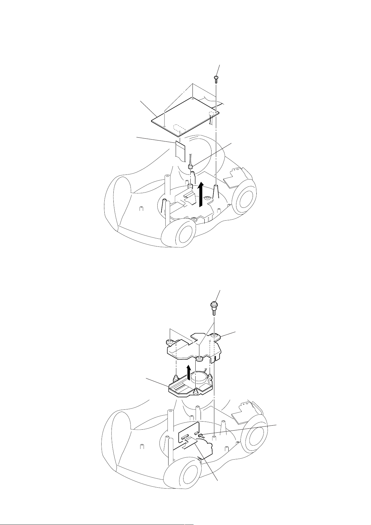
3-7. OPTICAL PICK-UP SECTION
5
optical pick-up section
1
three PWH tapping screws
2
holder upper
4
connecto
(CNP704
3
flexible board (optical pick-up)
(CNP703)
11

ZS-X3CP
p
3-8. SLED MOTOR ASSY (780CP) (M702)
1
screw
(2
×
2
holder (780C)
8)
3
screw
(M2
×
2.5)
5
two solders
4
6
sled motor assy (780CP) (M702)
3-9. OPTICAL PICK-UP (KSS-900A)
7
sled screw assy (780C)
1
screw
×
8)
(2
2
holder (780C)
5
rack spring (780C)
6
4
screw
(B1.7
×
4)
8
optical pick-u
(KSS-900A)
12
3
gear (B) (780C)
3-10. CABINET FRONT SECTION
1
two screws
(BVTP3
×
ZS-X3CP
10)
2
cabinet front section
1
two screws
(BVTP3
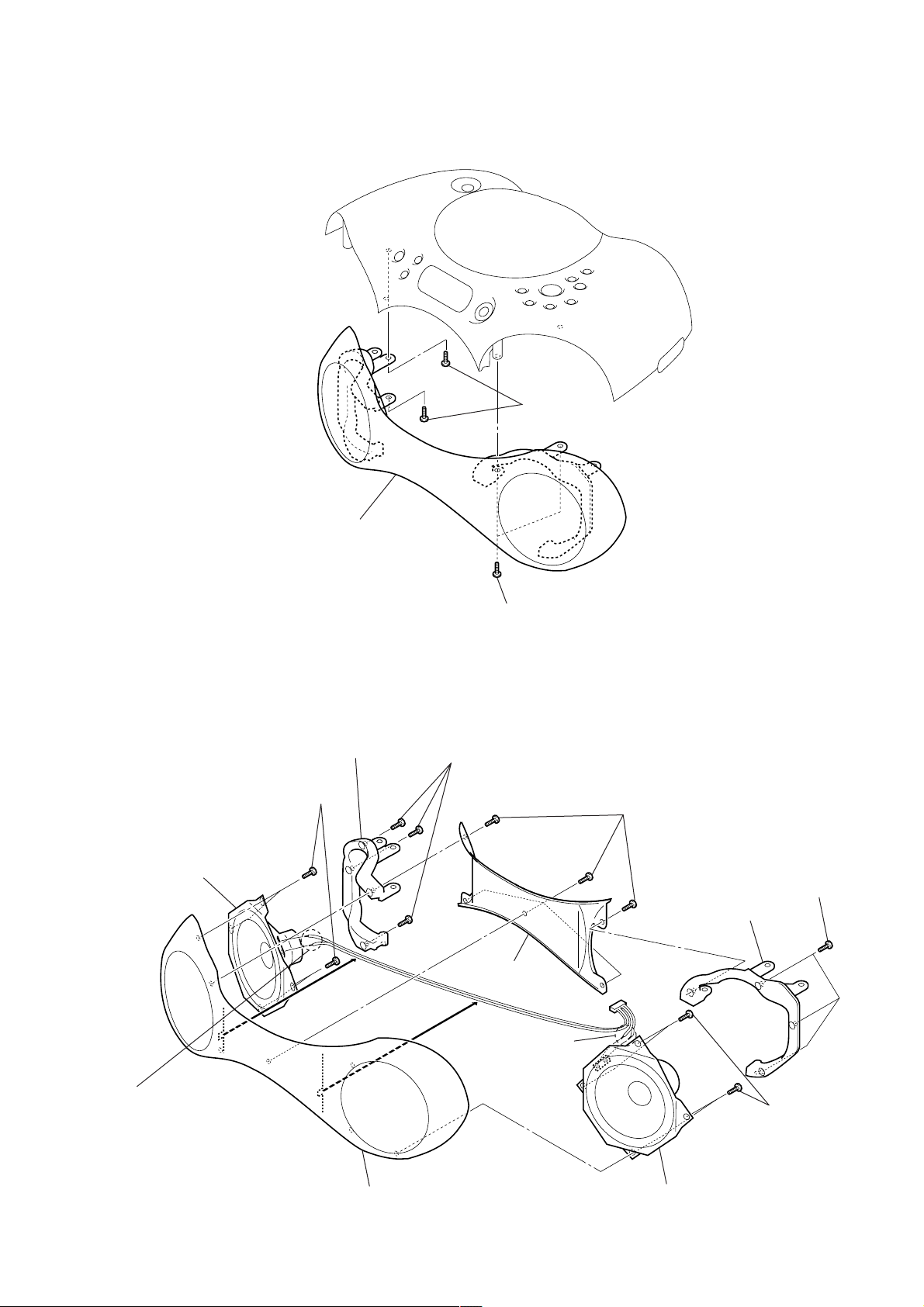
3-11. SPEAKER UNIT (L) (SP1), SPEAKER UNIT (R) (SP2)
8
three screws
×
2
handle cover
10)
(BVTP3
qs
speaker unit (R)
(SP2)
qa
four screws
(BVTP3
9
holder front (L)
×
10)
×
10)
1
five screws
(BVTP3
×
10)
4
holder front (R)
3
three screws
(BVTP3
×
10)
0
Remove two solders.
5
Remove two solders.
qd
cabinet front sub assy
7
speaker unit (L) (SP1)
6
four screws
(BVTP3
×
10)
13
ZS-X3CP
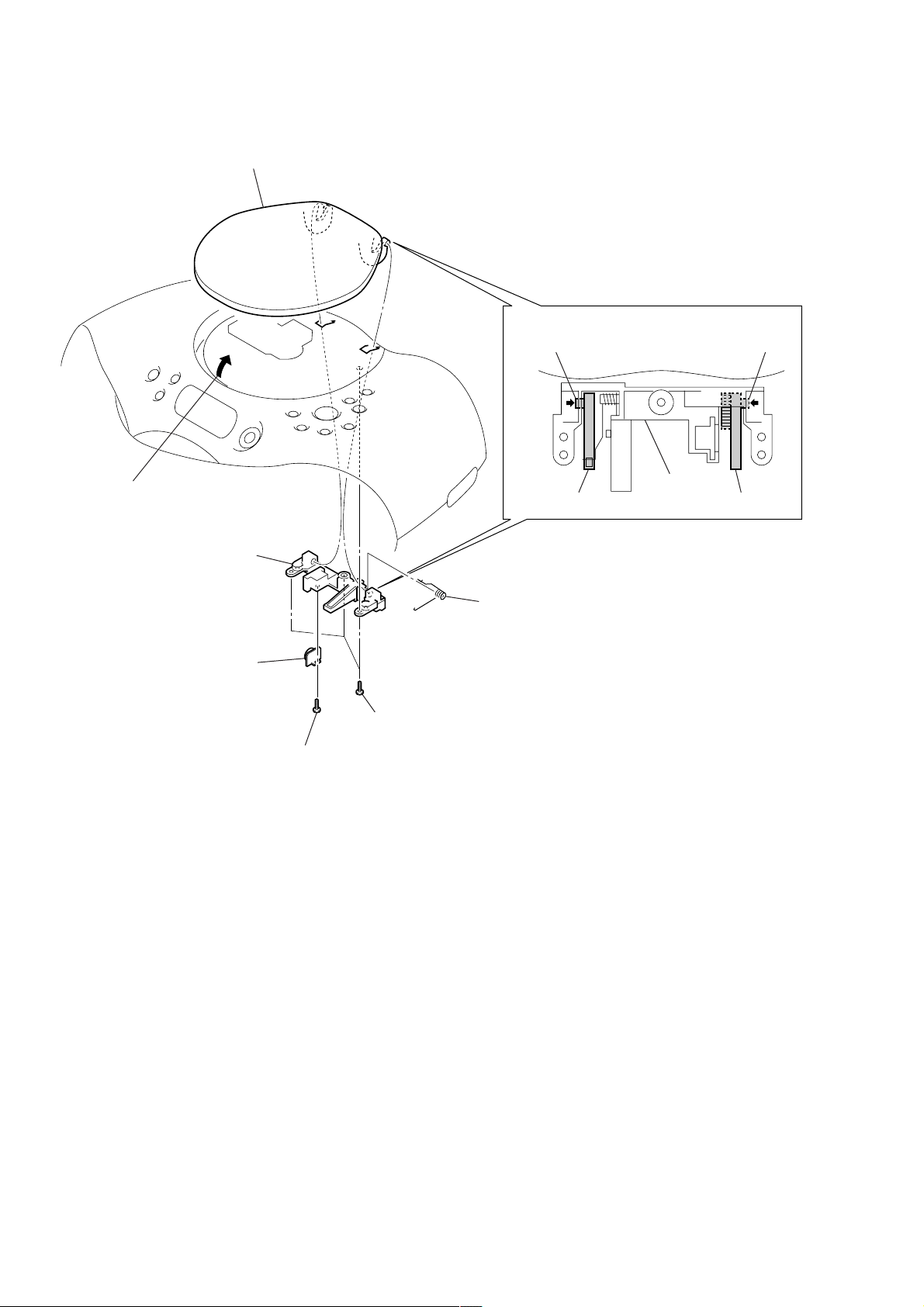
3-12. LID CD
8
lid CD
4
claw
4
claw
7
Open the lid CD.
5
holder CD
2
damper
1
screw
(BVTP3
×
3
10)
three screws
(BVTP3 × 10)
6
spring CD
holder CD
lid CD lid CD
14
r
SECTION 4
ELECTRICAL ADJUSTMENTS
ZS-X3CP
PRECAUTION
1. Setting
MEGA BASS control : OFF
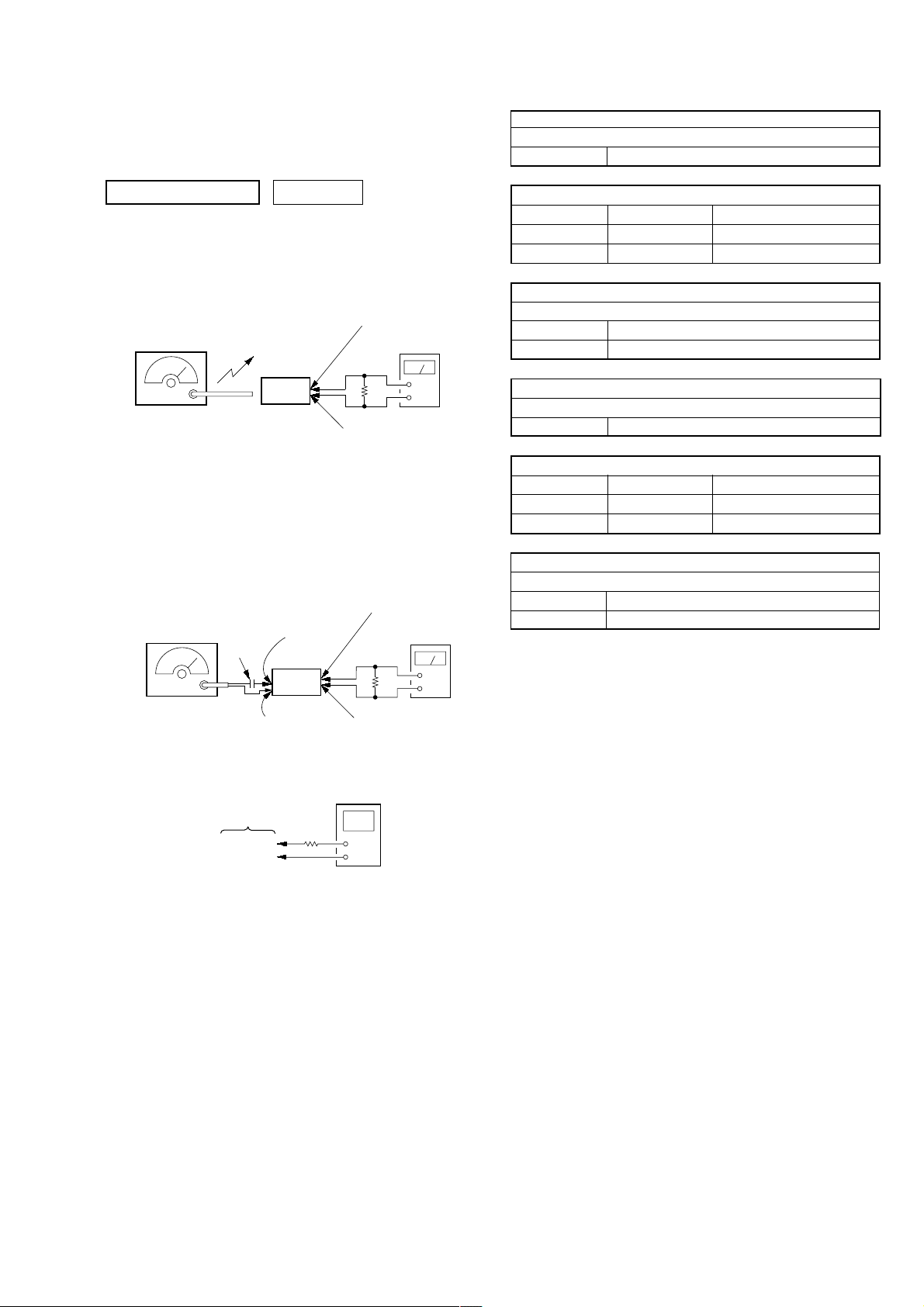
TUNER SECTION 0 dB=1 µV
[AM]
Setting:
Function: RADIO
BAND/AUTO PRESET button: AM
AM RF signal
generator
30% amplitude
modulation by
400 Hz signal
Output level:
as low as possible
[FM]
Setting:
Function: RADIO
BAND/AUTO PRESET button: FM
FM RF signal
generator
22.5 kHz frequency
deviation by 400 Hz
signal
Output level:
as low as possible
Put the lead-wire
antenna close to
the set.
set
TUNER board
TP (ANT)
0.01 µF
set
TUNER board
TP (GND)
AUDIO board
CN302 pin
3.2
AUDIO board
CN302 pin
AUDIO board
CN302 pin
1
level meter
Ω
2
AUDIO board
CN302 pin
level meter
3.2
Ω
AM IF ADJUSTMENT
Adjust for a maximum reading on level meter
T1 450 kHz
AM VCO VOLTA GE ADJUSTMENT
Adjustment Part Frequency Display Reading on Digital Voltmeter
L4 530 kHz 1.0 ± 0.05 V
Confirmation 1,710 kHz 5.3 ± 0.7 V
AM TRACKING ADJUSTMENT
Adjust for a maximum reading on level meter
L3 620 kHz
CT3 1,400 kHz
+
–
Adjustment Part Frequency Display Reading on Digital Voltmeter
Confirmation 87.5 MHz 1.3 ± 0.3 V
1
Adjust for a minimum reading on level meter
T2 10.7 MHz
L2 108 MHz 3.0 ± 0.2 V
Adjust for a maximum reading on level meter
L1 87.5 MHz
CT1 108 MHz
FM IF ADJUSTMENT
FM VCO VOLTA GE ADJUSTMENT
FM TRACKING ADJUSTMENT
Adjustment Location: TUNER and AUDIO boards (See page 16)
+
–
2
digital voltmete
TUNER board
TP (VT)
TP (GND)
100 kΩ
• Repeat the procedures in each adjustment several times, and the
tracking adjustments should be finally done by the trimmer capacitors.
• Remove FM antenna in FM adjustment.
15

ZS-X3CP
Adjustment Location:
– TUNER BOARD (Component Side) –
AM VCO Voltage Adjustment
FM VCO Voltage Adjustment
AM T rac king Adjustment
L4
L2
CT3
L3
– TUNER BOARD (Conductor Side) –
TP
(VT)
TP
(GND)
TP
(ANT)
T2 FM IF Adjustment
T1 AM IF Adjustment
L1
FM T rac king Adjustment
CT1
– AUDIO BOARD (Conductor Side) –
14
CN302
16
 Loading...