

Sony ZSS2IPW, ZS-S2iP Service Manual
SERVICE MANUAL
Sony Corporation
Personal Audio Division
Published by Sony Techno Create Corporation
US Model
Canadian Model
PERSONAL AUDIO SYSTEM
9-887-823-01
2007H04-1
© 2007. 08
Ver. 1.0 2007. 08
SPECIFICATIONS
ZS-S2iP
AUDIO POWER SPECIFICATIONS
POWER OUTPUT AND TOTAL HARMONIC DISTORTION
With 4-ohm loads, both channels driven from 150 -10,000 Hz; rated
1 W per channel-minimum RMS power, with no more than 10 % total
harmonic distortion in AC operation.
Other specifications
CD player section
System
Compact disc digital audio system
Laser diode properties
Emission duration: Continuous
Laser output: Less than 44.6 µW
(This output is the value measured at a distance of
about 200 mm from the objective lens surface on the
optical pick-up block with 7 mm aperture.)
Number of channels
2
Frequency response
20 – 20 000 Hz +1/–2 dB
Wow and flutter
Below measurable limit
Radio section
Frequency range
FM: 87.5 – 108 MHz
AM:530 – 1,710 kHz
Antennas
FM: Telescopic antenna
AM: Built-in ferrite bar antenna
iPod section
DC out: 5 V
MAX: 500 mA
(AC only)
Compatible iPod models
The compatible iPod models are as follows. Update
your iPod to use the latest software before you use it.
CD
Model Name Using Similar Mechanism CFD-S01
Section
CD Mechanism Type KSM-213CDP
Optical Pick-up Name KSS-213C
– Continued on next page –
iPod nano 2nd
generation
(aluminium)
iPod 5th
generation (video)
iPod nano 1st
generation
iPod 4th generation
(color display)
iPod 4th
generation
iPod mini
2
ZS-S2iP
General
Speaker
Full range: 8 cm (3
1/4 inches) dia., 4 Ω,
cone type (2)
Outputs
Headphones jack (stereo minijack):
For 16 – 32 Ω impedance headphones
Input
AUDIO IN jack (stereo minijack)
Power output
1.7 W + 1.7 W (at 4 Ω, 10% harmonic distortion)
Power requirements
For CD player:
120 V AC, 60Hz
9 V DC, 6 R14 (size C) batteries
Power consumption
AC 17 W
Battery life
For player:
FM reseption
Sony R14P: approx. 6 h
Sony alkaline LR14: approx. 20 h
CD playback
Sony R14P: approx. 1.5 h
Sony alkaline LR14: approx. 7 h
Dimensions
Approx. 360 × 141.5 × 240.5 mm (w/h/d)
(14 1/4 × 5 5/8 × 9 1/2 inches)
(incl. projecting parts)
Mass
Approx. 2.7 kg (5 lb, 15 oz) (incl. batteries)
Supplied accessory
AC power cord (1)
Remote control (1)
Design and specifications are subject to change
without notice.
SAFETY CHECK-OUT
After correcting the original service problem, perform the following
safety check before releasing the set to the customer:
Check the antenna terminals, metal trim, “metallized” knobs, screws,
and all other exposed metal parts for AC leakage.
Check leakage as described below.
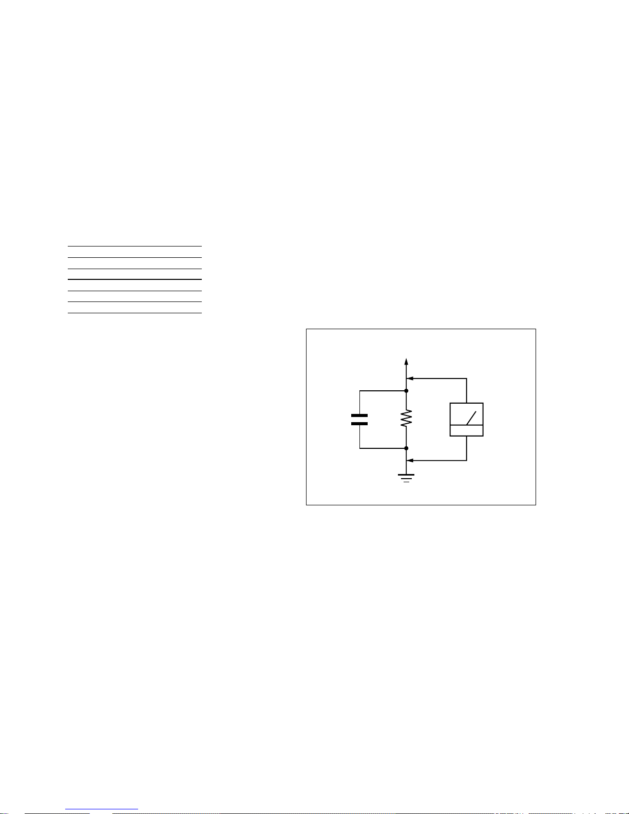
LEAKAGE TEST
The AC leakage from any exposed metal part to earth ground and
from all exposed metal parts to any exposed metal part having a
return to chassis, must not exceed 0.5 mA (500 microampers.).
Leakage current can be measured by any one of three methods.
1. A commercial leakage tester, such as the Simpson 229 or RCA
WT-540A. Follow the manufacturers’ instructions to use these
instruments.
2. A battery-operated AC milliammeter. The Data Precision 245
digital multimeter is suitable for this job.
3. Measuring the voltage drop across a resistor by means of a
VOM or battery-operated AC voltmeter. The “limit” indication is 0.75 V, so analog meters must have an accurate lowvoltage scale. The Simpson 250 and Sanwa SH-63Trd are
examples of a passive VOM that is suitable. Nearly all battery
operated digital multimeters that have a 2 V AC range are
suitable. (See Fig. A)
1.5 k
Ω
0.15 µF
AC
voltmete
r
(0.75 V)
To Exposed Metal
Parts on Set
Earth Ground
Fig. A. Using an AC voltmeter to check AC leakage.
SAFETY-RELATED COMPONENT WARNING!!
COMPONENTS IDENTIFIED BY MARK 0 OR DOTTED LINE
WITH MARK 0 ON THE SCHEMATIC DIAGRAMS AND IN
THE PARTS LIST ARE CRITICAL TO SAFE OPERATION.
REPLACE THESE COMPONENTS WITH SONY P ARTS WHOSE
PART NUMBERS APPEAR AS SHOWN IN THIS MANUAL OR
IN SUPPLEMENTS PUBLISHED BY SONY.
ATTENTION AU COMPOSANT AYANT RAPPORT
À LA SÉCURITÉ!!
LES COMPOSANTS IDENTIFIÉS PAR UNE MARQUE 0 SUR LES
DIAGRAMMES SCHÉMATIQUES ET LA LISTE DES PIÈCES
SONT CRITIQUES POUR LA SÉCURITÉ DE FONCTIONNEMENT .
NE REMPLACER CES COMPOSANTS QUE PAR DES PIÈCES
SONY DONT LES NUMÉROS SONT DONNÉS DANS CE MANUEL
OU DANS LES SUPPLÉMENTS PUBLIÉS PAR SONY.

3
ZS-S2iP
CAUTION
Use of controls or adjustments or performance of procedures
other than those specified herein may result in hazardous
radiation exposure.
Flexible Circuit Board Repairing
•Keep the temperature of the soldering iron around 270˚C during
repairing.
• Do not touch the soldering iron on the same conductor of the
circuit board (within 3 times).
• Be careful not to apply force on the conductor when soldering or
unsoldering.
Notes on Chip Component Replacement
•Never reuse a disconnected chip component.
• Notice that the minus side of a tantalum capacitor may be damaged
by heat.
NOTES ON HANDLING THE OPTICAL PICK-UP BLOCK
OR BASE UNIT
The laser diode in the optical pick-up block may suffer electrostatic
breakdown because of the potential difference generated by the
charged electrostatic load, etc. on clothing and the human body.
During repair, pay attention to electrostatic breakdown and also use
the procedure in the printed matter which is included in the repair
parts.
The flexible board is easily damaged and should be handled with
care.
NOTES ON LASER DIODE EMISSION CHECK
The laser beam on this model is concentrated so as to be focused on
the disc reflective surface by the objective lens in the optical pickup block. Therefore, when checking the laser diode emission,
observe from more than 30 cm away from the objective lens.
Notes on DualDiscs
A DualDisc is a two sided disc product which mates DVD recorded
material on one side with digital audio material on the other side.
However, since the audio material side does not confor m to the
Compact Disc (CD) standard, playback on this product is not
guaranteed.
•
UNLEADED SOLDER
Boards requiring use of unleaded solder are printed with the leadfree mark (LF) indicating the solder contains no lead.
(Caution:Some printed circuit boards may not come printed with
the lead free mark due to their particular size.)
: LEAD FREE MARK
Unleaded solder has the following characteristics.
• Unleaded solder melts at a temperature about 40°C higher than
ordinary solder.
Ordinary soldering irons can be used but the iron tip has to be
applied to the solder joint for a slightly longer time.
Soldering irons using a temperature regulator should be set to
about 350°C.
Caution:The printed pattern (copper foil) may peel away if the
heated tip is applied for too long, so be careful!
• Strong viscosity
Unleaded solder is more viscous (sticky, less prone to flow)
than ordinary solder so use caution not to let solder bridges
occur such as on IC pins, etc.
• Usable with ordinary solder
It is best to use only unleaded solder but unleaded solder may
also be added to ordinary solder.

4
ZS-S2iP
TABLE OF CONTENTS
1. SERVICING NOTES ................................................ 5
2. GENERAL
Basic Operation ............................................................... 6
3. DISASSEMBLY
3-1. Cabinet (Rear) Assy ......................................................... 9
3-2. Cabinet (Front) Assy, Cabinet (Upper) Assy................... 9
3-3. Main Board...................................................................... 10
3-4. CD Block Assy, Reg Board ............................................. 10
3-5. CD Motor Board, Optical Pick-up .................................. 11
3-6. Control Board.................................................................. 11
3-7. CD Lid............................................................................. 12
3-8. Dock Block Assy ............................................................. 12
3-9. Dock Board...................................................................... 13
3-10. Key (FUNC) Board, Key (VOL) Board .......................... 13
3-11. Power Board .................................................................... 14
4. ELECTRICAL ADJUSTMENTS
Tuner Section................................................................... 15
CD Section ...................................................................... 17
5. DIAGRAMS
5-1. Block Diagram – CD Section –....................................... 19
5-2. Block Diagram – Main Section –.................................... 20
5-3. Circuit Boards Location .................................................. 21
5-4. Printed Wiring Board – Main Section (1/2) – ................. 22
5-5. Printed Wiring Boards – Main Section (2/2) –................ 23
5-6. Schematic Diagram – Main Section (1/4) – .................... 24
5-7. Schematic Diagram – Main Section (2/4) – .................... 25
5-8. Schematic Diagram – Main Section (3/4) – .................... 26
5-9. Schematic Diagram – Main Section (4/4) – .................... 27
5-10. Printed Wiring Board – Dock Section – .......................... 28
5-11. Schematic Diagram – Dock Section –............................. 29
5-12. Printed Wiring Boards – Control Section – ..................... 30
5-13. Schematic Diagram – Control Section – ......................... 31
5-14. Printed Wiring Boards – Power Supply Section –........... 32
5-15. Schematic Diagram – Power Supply Section –............... 33
6. EXPLODED VIEWS
6-1. Rear Cabinet Section....................................................... 40
6-2. Front Cabinet Section...................................................... 41
6-3. Dock Block Assy ............................................................. 42
6-4. Upper Cabinet Section (1)............................................... 43
6-5. Upper Cabinet Section (2)............................................... 44
7. ELECTRICAL PARTS LIST .................................. 45
5
ZS-S2iP
SECTION 1
SERVICING NOTES
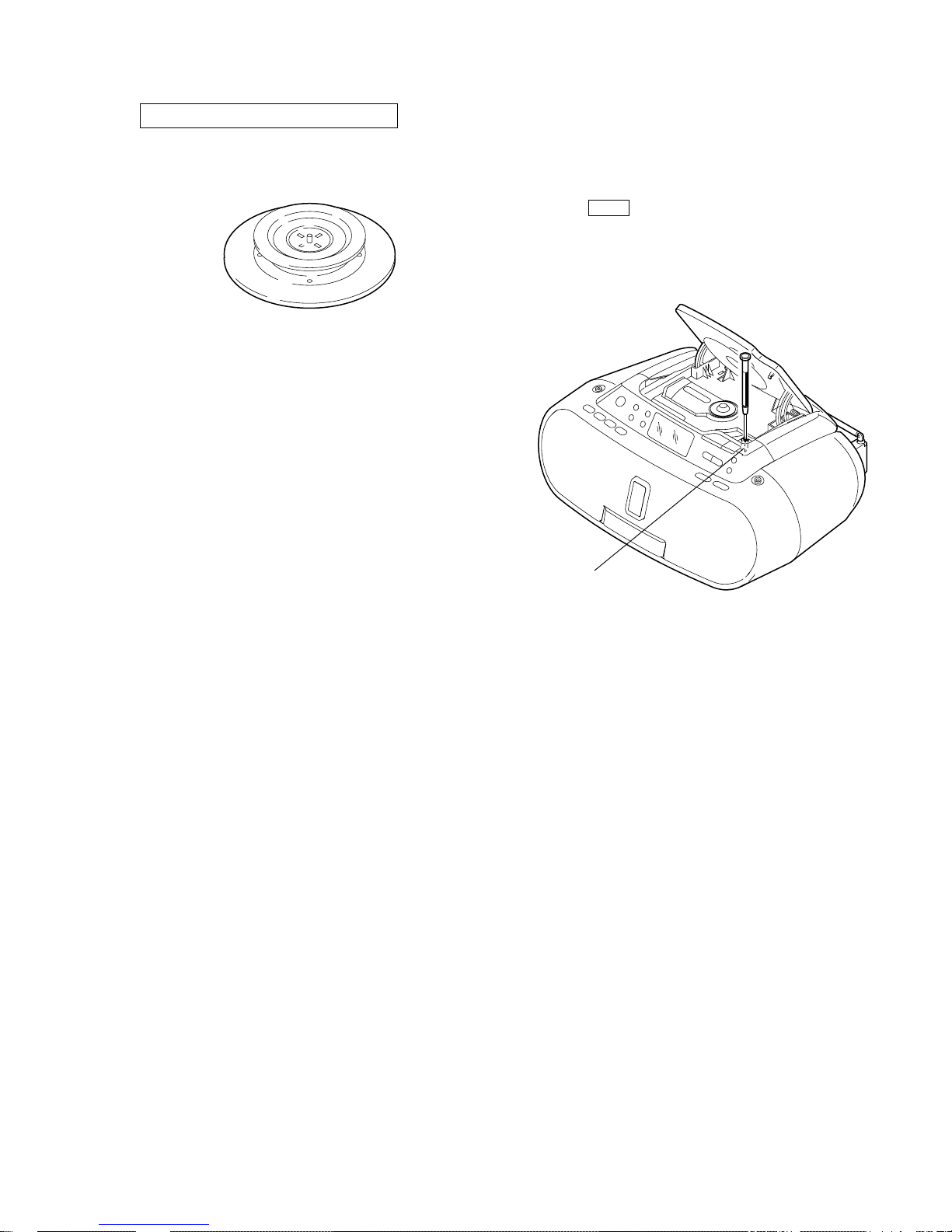
CHUCK PLATE JIG ON REPAIRING
On repairing CD section, playing a disc without the lid (CD), use
Chuck Plate Jig.
• Code number of Chuck Plate Jig: X-4918-255-1
LASER DIODE AND FOCUS SEARCH OPERA TION
CHECK
1. Turn ON the [POWER] button and press [CD] button to CD
position.
2. Open the CD lid.
3. Turn on S801 with screwdriver, etc. as following figure.
4. Press the N X (CD) button.
5. Confirm the laser diode emission while observing the objecting
lens. When there is no emission, Auto Power Control circuit or
Optical Pick-up is broken.
Objective lens moves up and do wn three times for focus search.
S801
6
ZS-S2iP
SECTION 2
GENERAL
This section is extracted
from instruction manual.
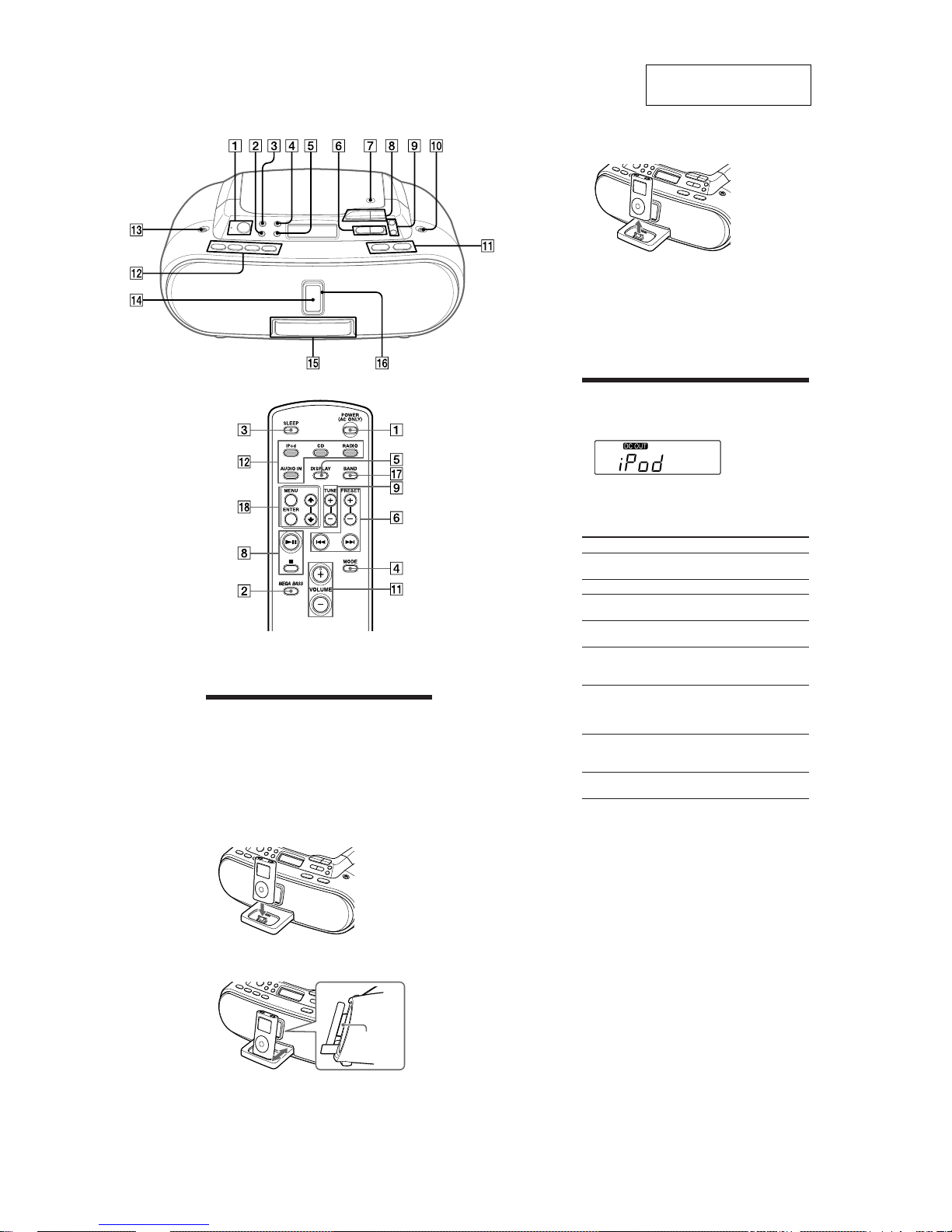
• BASIC OPERATIONS
V
VOLUME + qa have a tactile dot.
OLUME + qa and u 8 have a tactile dot.
Playing the iPod
1
2
Press iPod qs (direct power-on).
“DC OUT” appears in the display (AC only).
Press
u
8
.
The iPod begins to play.
You can operate the connected iPod by the unit or the
iPod buttons.
To Press
Pause playback
u
8
To resume play, press it again.
Stop playback
x
8
Go to the next
track
>
6
Go back to the
previous track
.
6
Locate a point
while listening to
the sound
>
(forward) or . (backward)
6
while playing and hold it until
you find the point.
Locate a point
while observing
on the iPod
display
>
(forward) or . (backward)
6
in pause and hold it until you
Select a menu Press MENU and
find the point.
M
or
m
qk
on the
remote to select a menu, and then
press ENTER
qk
.
Go back to the
previous menu
Press MENU
qk
on the remote.
Notes
• You may use the universal adaptor supplied with your iPod for a
more customized fit.The iPod may be docked without the use of an
adaptor.
• If you connect the iPod when another function is in use, the
function will change to iPod automatically.
• Apple’s iPod Universal Dock Adapter (not supplied) can be used
with this unit.
• To use an iPod, refer to the user’s guide of your iPod.
• Before disconnecting the iPod, pause playback.
To use the unit as a battery charger (AC
only)
You can use the unit as a battery charger. The charging
status appears in the iPod display. For details, see the
user’s guide of your iPod.
On copyrights
• iPod is a trademark of Apple Inc., registered in the U.S.
and other countries.
• All other trademarks and registered trademarks are
of their respective holders. In this manual, ™ and ®
marks are not specified.
Opening/closing the Sliding Tray
Setting the iPod
1
Press the PUSH OPEN/CLOSE button qf.
The Sliding Tray
qg
is ejected half way.
2
Pull the Sliding Tray qg all the way out.
3
4
5
Attach the iPod Universal Dock Adapter if
necessary (not supplied).
Place your iPod on the Sliding Tray
qg
.
Push in and adjust the Sliding Tray qg so that the
iPod fits on the Back Support
qh
.
Back
Support
Closing the Sliding Tray
1
Remove the iPod
Push the Sliding Tray qg until it clicks.
3
2
Press the PUSH OPEN/CLOSE button qf.
4
Push the Sliding Tray qg into the unit.
Notes
• Do not carry the unit with an iPod set on the connector. Doing so
may cause a malfunction.
• Be sure to store the Sliding Tray
qg
before moving the unit.
7
ZS-S2iP
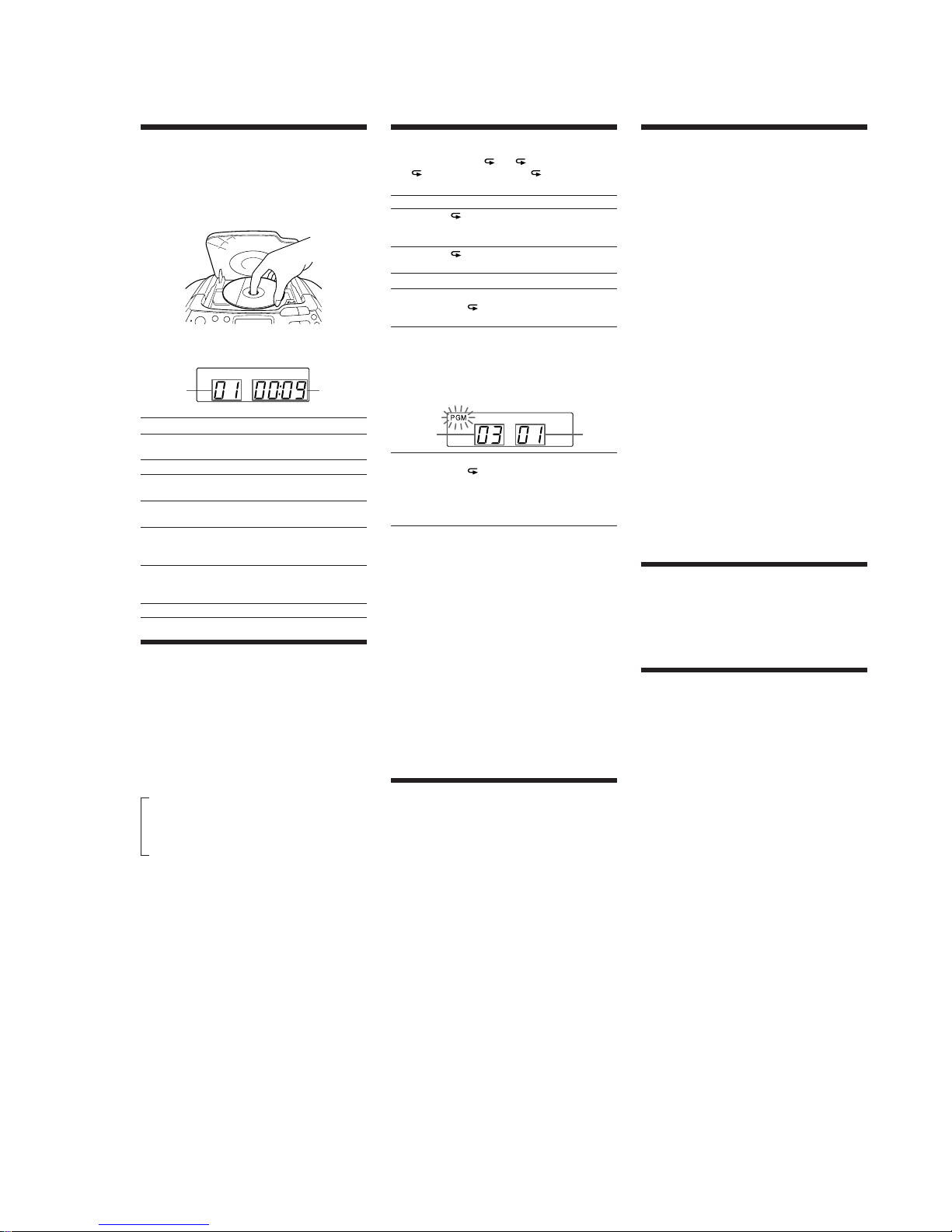
Selecting the play mode
Press MODE 4 until “ 1”, “ ”, “SHUF”, “SHUF”
and “ ”, “PGM”, or “PGM” and “ ” appear in
the display. Then proceed as follows:
To Select Select Then do this
Repeat a
single track
“ 1” Press . or > 6 to
select the track that you want
to repeat, then press
u
8
.
Repeat all
tracks
“ ”
Press
u
8
.
Shuffle play “SHUF” Press
u
8
.
Repeat tracks
in random
order
“SHUF”
and “ ”
Press
u
8
.
Program
play
“PGM” Press
.
or > 6 then
press DISPLAY•ENTER
5
or ENTER
qk
on the remote
for the tracks (up to 20) you
want to program in the order
you want. Then press
u
8
.
Programed
track
Playing
order
Repeat
programed
tracks
“PGM”
and “ ”
Press . or
>
6
then
press DISPLAY•ENTER
5
or ENTER
qk
on the remote
for the tracks (up to 20) you
want to program in the order
you want. Then Press
u
8
.
To cancel the selected play mode
Press MODE 4 repeatedly until the selected mode
disappears from the display.
To check the programed track and playing
order in the display
To check the order of tracks before play, press
DISPLAY•ENTER
5
or ENTER qk on the remote.
Every time you press the button, the track number
appears in the programed order.
To change the current program
Press x 8 once if the CD is stopped and twice if the
CD is playing. The current program will be erased.
Then create a new program following the programing
procedure.
Tip
You can play the same program again, since the program is saved
until you open the CD compartment.
Listening to the radio
1
Press RADIO•BAND•AUTO PRESET qs
repeatedly (direct power-on) or press RADIO
qs
and press BAND
qj
repeatedly on the remote.
Each time you press the button, the indication
changes as follows:
“FM” y “AM”
2
Hold down TUNE + or – 9 until the frequency
digits begin to change in the display.
The player automatically scans the radio frequencies
and stops when it finds a clear station.
If you can’t tune in a station, press the button
repeatedly to change the frequency step by step.
When an FM stereo broadcast is received, “ST”
appears.
Tips
• If the FM broadcast is noisy, press MODE 4 until “Mono” appears
in the display and the radio will play in monaural.
• If you touch or operate an iPod connected to this unit while
listening to AM/FM, noise may occur. Avoid touching or operating
the iPod in this case.
• If you hear noise from the AM/FM while supplying power to
iPod (“DC OUT” indicator appears in the display), press and hold
MODE for a few seconds to stop the power supply to the iPod (“DC
OUT” indicator disappears from the display).
Presetting radio stations
You can store radio stations into the player’s memory.
You can preset up to 30 radio stations, 20 for FM and 10
for AM in any order.
1
Press RADIO•BAND•AUTO PRESET qs or
BAND
qj
on the remote to select the band.
2
Hold down RADIO•BAND•AUTO PRESET qs
or RADIO
qs
on the remote for 2 seconds until
“AUTO” flashes in the display.
3
Press DISPLAY•ENTER 5or ENTER qk on the
remote.
The stations are stored in memory from the lower
frequencies to the higher ones.
If a station cannot be preset automatically
You need to preset a station with a weak signal
manually.
1
Press RADIO•BAND•AUTO PRESET qs or
BAND
qj
on the remote to select the band.
2
Tune in a station you want.
3
Hold down DISPLAY•ENTER 5 or ENTER qk
on the remote for 2 seconds until the preset
number flashes in the display.
4
Press PRESET + or – 6 until the preset number
you want for the station flashes in the display.
5
Press DISPLAY•ENTER 5 or ENTER qk on the
remote.
The new station replaces the old one.
Tip
The preset radio stations remain in memory even if you unplug the
AC power cord or remove the batteries.
Playing preset radio stations
1
Press RADIO•BAND•AUTO PRESET qs or
BAND
qj
on the remote to select the band.
2
Press PRESET + or – 6 to tune in the stored
station.
Connecting optional components
You can enjoy the sound from an optional component
such as a portable digital music player through the
speakers of this unit. Be sure to turn off the power of
each component before making any connections. For
details, refer to the instruction manual of the component
to be connected.
1
Connect the AUDIO IN jack q; on the unit to
the line output jack of the portable digital music
player or other components using an audio
connecting cable (not supplied).
2
Turn the unit and the connected component on.
3
Press AUDIO IN qs and start playing sound on
the connected component.
The sound from the connected component is output
from the speakers.
To connect the unit to a TV or VCR, use an extension
cable (not supplied) with a stereo-mini jack on one
end and two phono plugs on the other end.
Playing a CD
1
Press CD qs (direct power-on).
2
3
Press Z PUSH OPEN/CLOSE 7 and place a disc
with the label side up in the CD compartment.
To close the CD compartment, press Z PUSH OPEN/
CLOSE
7
.
Press u8.
The player plays all the tracks once.
Track Playing
number
time
To Press
Pause playback
u
8
To resume play, press it again.
Stop playback
x
8
Go to the next
track
>
6
Go back to the
previous track
.
6
Locate a point
while listening to
the sound
>
(forward) or . (backward)
6
while playing and hold it until
you find the point.
find the point.
Locate a point
while observing
the display
>
(forward) or . (backward)
6
in pause and hold it until you
Remove the CD
Z
PUSH OPEN/CLOSE
7
Using the display
To check the total track number and playing
time
In stop mode, press DISPLAY•ENTER 5 or DISPLAY
5
on the remote.
To check the remaining time
Press DISPLAY•ENTER 5 or DISPLAY 5 on the
remote repeatedly while playing a CD. The display
changes as follows:
The current track number and playing time
B
r
The current track number and the remaining
time of the current track*
r
The number of tracks left and remaining
time on the CD
* For a track whose number is more than 20, the remaining time
appears as “- -:- -” in the display.
8
ZS-S2iP
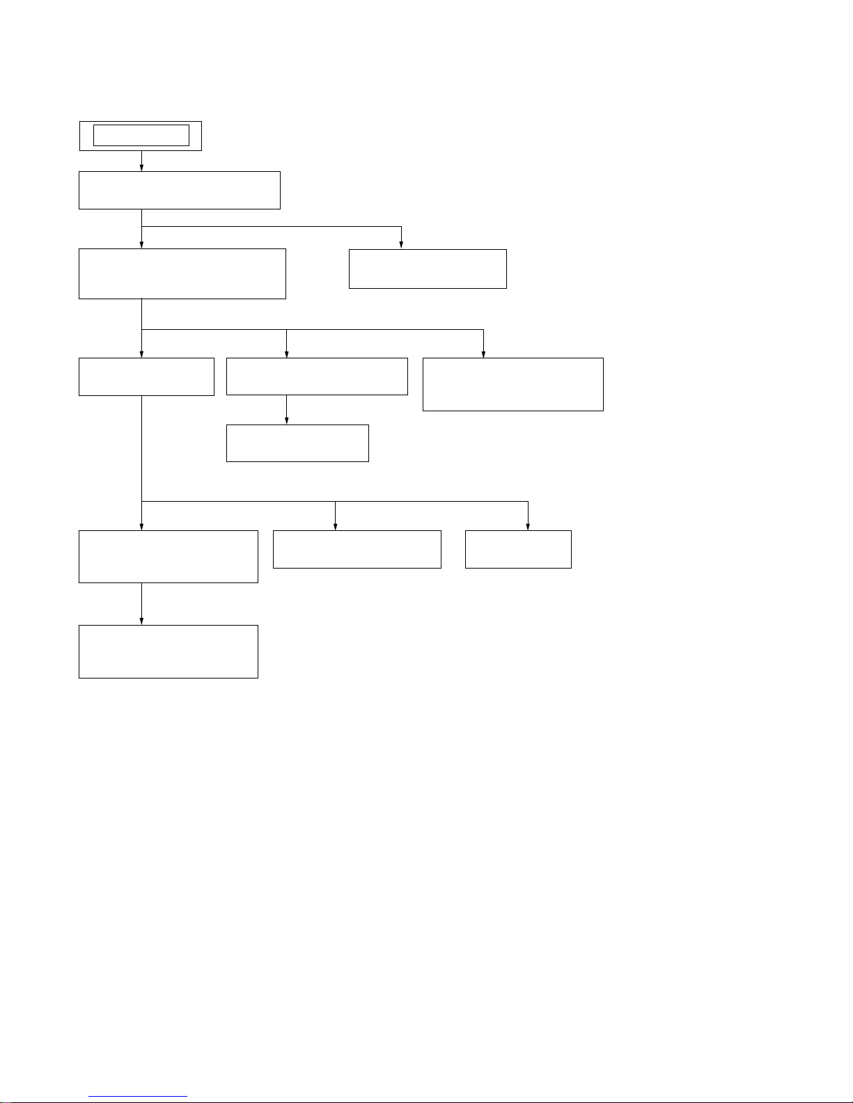
SECTION 3
DISASSEMBLY
Note: This set can be disassemble according to the following sequence.
3-1. CABINET (REAR) ASSY
(Page 9)
3-2. CABINET (FRONT) ASSY,
CABINET (UPPER) ASSY
(Page 9)
SET
3-3. MAIN BOARD
(Page 10)
3-8. DOCK BLOCK ASSY
(Page 12)
3-9. DOCK BOARD
(Page 13)
3-4. CD BLOCK ASSY,
REG BOARD
(Page 10)
3-5. CD MOTOR BOARD,
OPTICAL PICK-UP
(Page 11)
3-6. CONTROL BOARD
(Page 11)
3-7. CD LID
(Page 12)
3-11. POWER BOARD
(Page 14)
3-10. KEY (FUNC) BOARD,
KEY (VOL) BOARD
(Page 13)
9
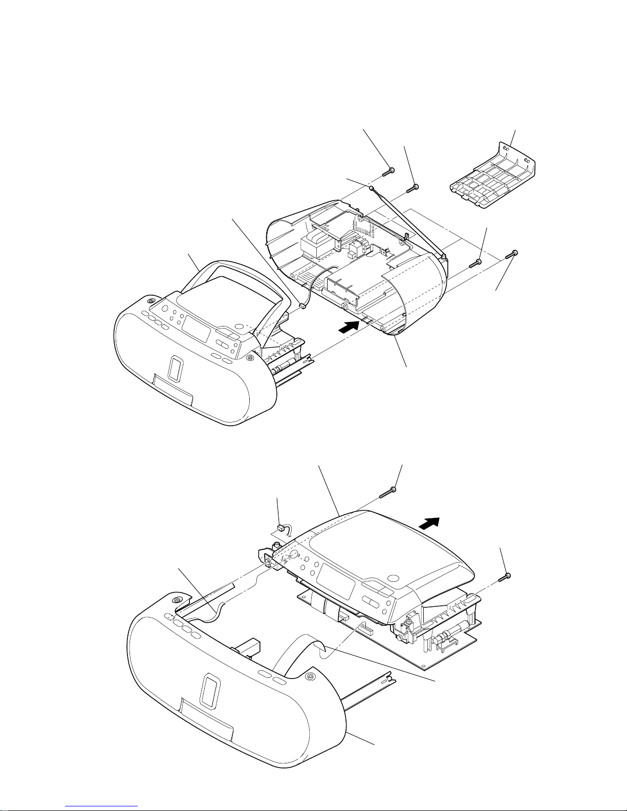
ZS-S2iP
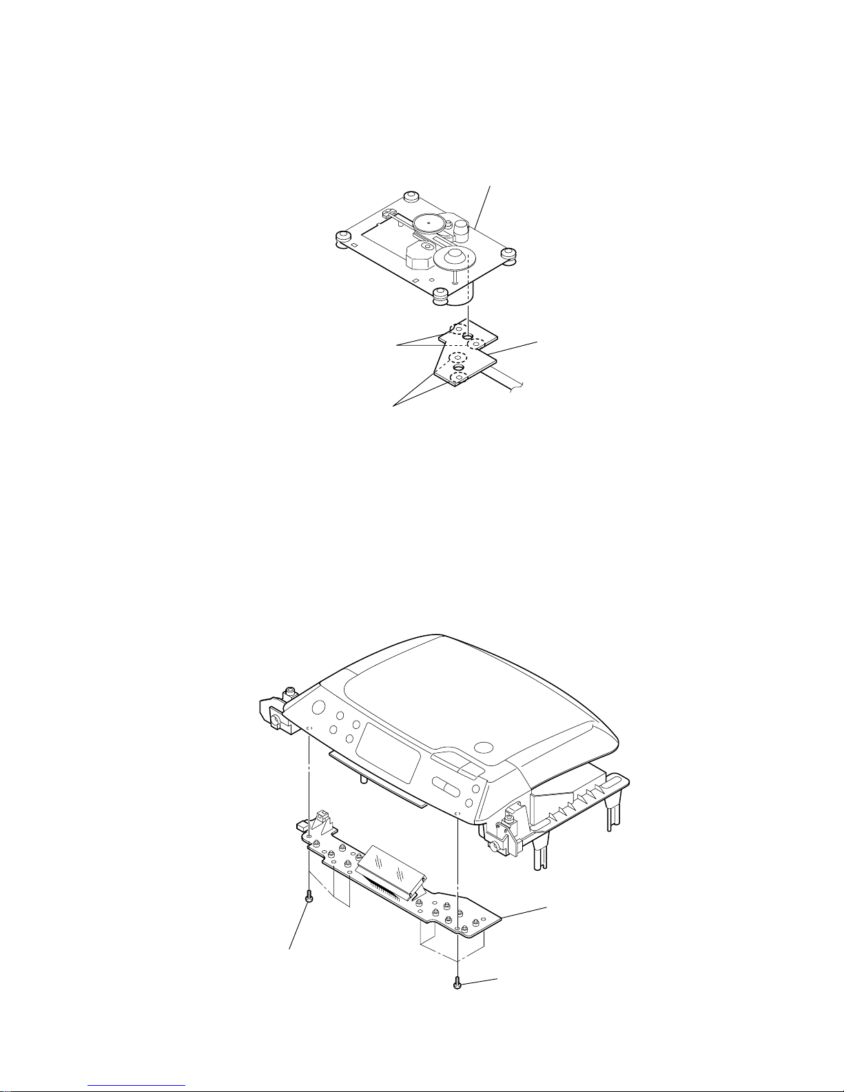
3-2. CABINET (FRONT) ASSY, CABINET (UPPER) ASSY
Note: Follow the disassembly procedure in the numerical order given.
3-1. CABINET (REAR) ASSY
5
two
screws
(+BV tapping (B2.6))
1
battery case lid
7
CN305 (5P)
8
cabinet (rear) assy
2
three
screws
(+BV tapping (B2.6)
)
3
screw
(+BV tapping (B2.6))
4
screw
(+BV tapping (B2.6))
6
handle
telescopic antenna
2
screw
(+BV tapping (B2.6))
3
screw
(+BV tapping (B2.6)
)
1
CN308 (4P)
5
flexible flat cable (4 core)
(CN402)
6
flexible flat cable (15 core)
(CN805)
8
cabinet (front) assy
7
cabinet (upper) assy
4
10
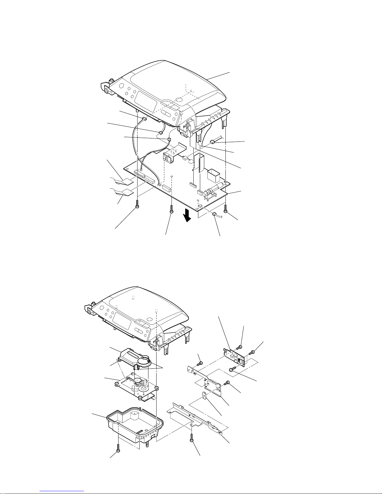
ZS-S2iP
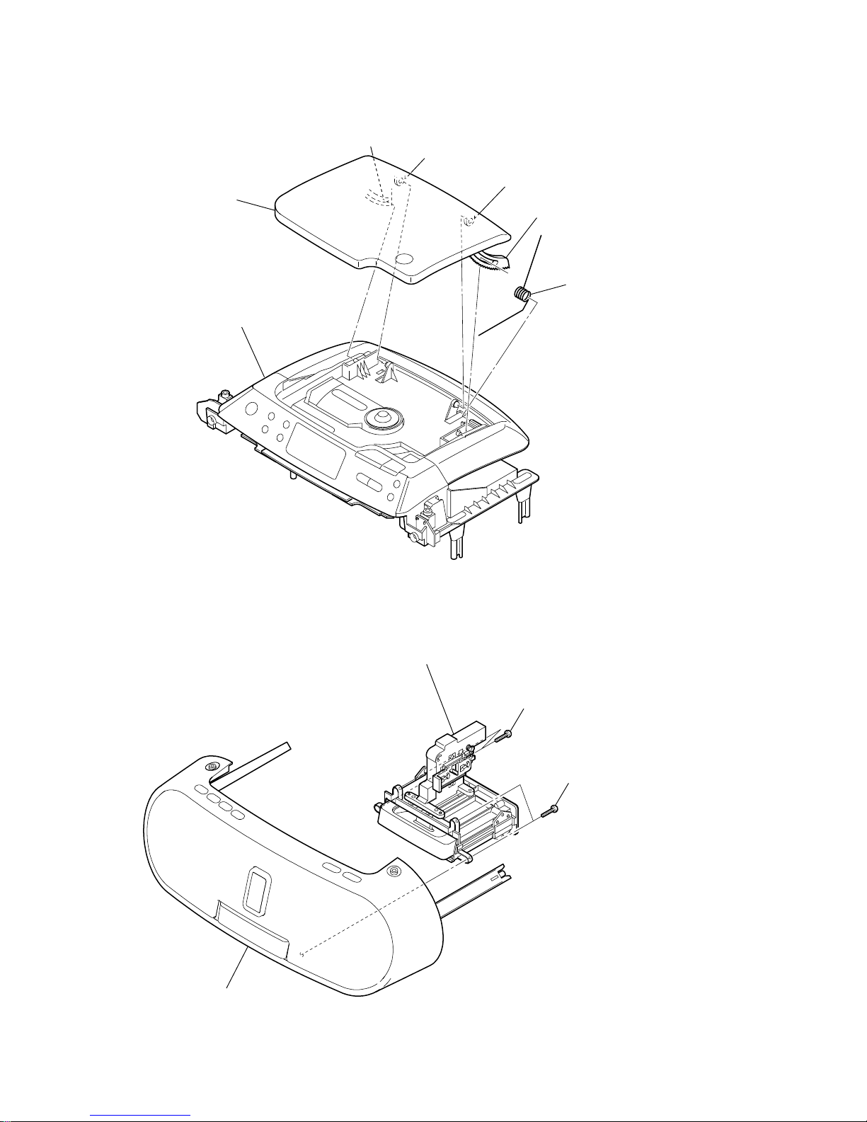
3-4. CD BLOCK ASSY, REG BOARD
3-3. MAIN BOARD
8
two
screws
(+BV tapping (B2.6))
6
two
screws
(+BV tapping (B2.6))
7
screw
(+BV tapping (B2.6))
9
qf
MAIN board
cabinet (upper) assy
1
CN306 (4P)
qd
CN906 (3P)
3
CN301 (3P)
2
CN311 (4P)
qs
connector
(S801)
4
flexible flat cable (15 core)
(CN802)
5
flexible flat cable (14 core)
(CN801)
0
flexible flat cable (16 core
)
(CN701)
qa
flexible flat cable (6 core)
(CN702)
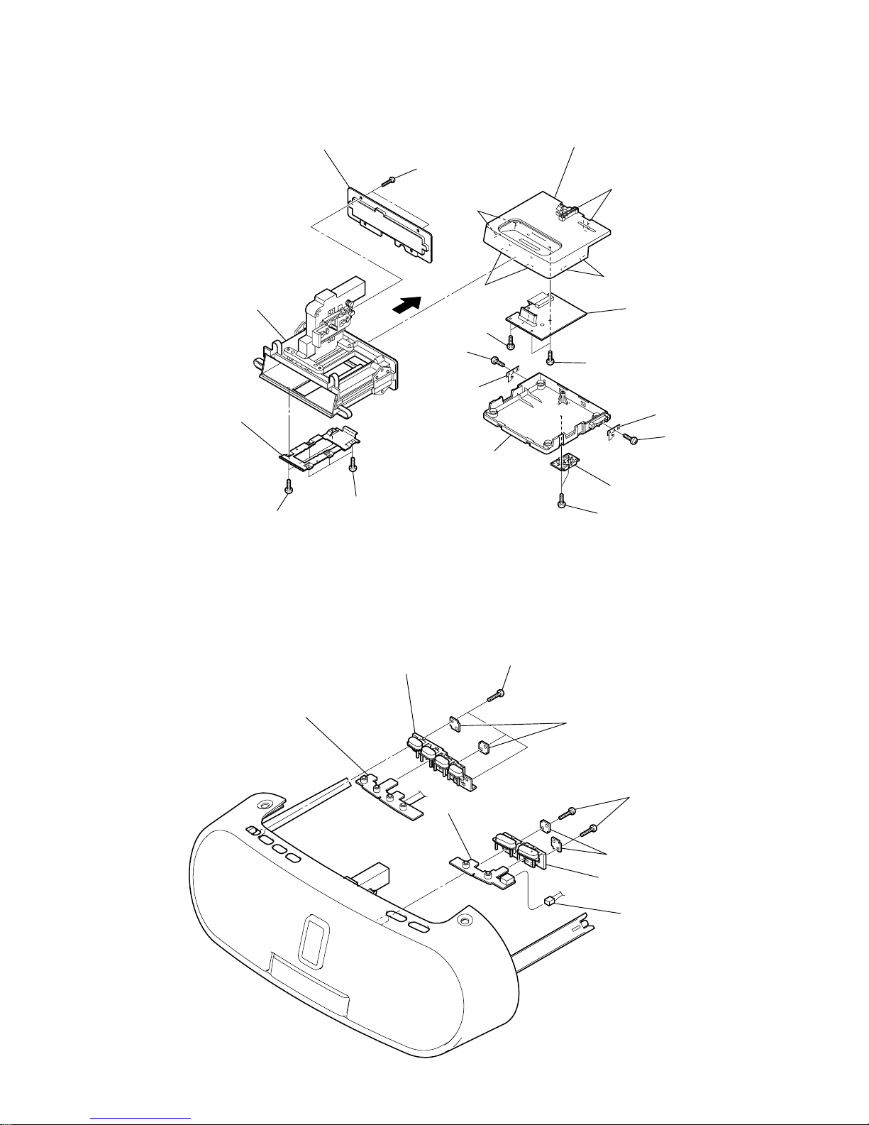
1
two
screws
(+BV tapping (B2.6))
5
holder (REG)
qs
CD chassis
qd
CD cover
qf
CD block assy
claw
two claws
qa
two
screws
(+BV tapping (B2.6))
2
screw
(+BVTP 2.6
×
8)
8
screw
(+BVTP 2.6
×
8)
7
two
screws
(+BVTP 2.6
×
8)
6
screw
(+BVTT 3
×
6)
4
RETAINER board
0
heat sink (REG IP)
9
REG board
3
screw
(+BVTP 2.6
×
8)
11
ZS-S2iP
3-6. CONTROL BOARD
3-5. CD MOTOR BOARD, OPTICAL PICK-UP
1
Remove the two solders.
3
CD MOTOR boar
d
4
optical pick-up
2
Remove the two solders.
1
four
screws
(+P tapping (B2.6))
3
CONTROL board
2
three
screws
(+P tapping (B2.6))
12
ZS-S2iP
3-8. DOCK BLOCK ASSY
3-7. CD LID
5
CD lid
6
CD spring
cabinet (upper) assy
3
4
2
1
2
two
screws
(+BV tapping (B2.6)
)
1
two
screws
(+BV tapping (B2.6))
3
dock block assy
cabinet (front) assy
13
ZS-S2iP
3-10. KEY (FUNC) BOARD, KEY (VOL) BOARD
3-9. DOCK BOARD
qj
cover (dock lower)
qd
two claws
qg
two claws
qf
two claws
qh
two claws
3
three
screws
(+BTP 2
×
4)
4
three
screws
(+BTP 2
×
4)
6
two
screws
(+BTP 2
×
4)
ql
two
screws
(+BTP 2
×
4)
qk
two
screws
(+BTP 2
×
4)
w;
DOCK board
wa
case (dock upper) sub assy
8
screw
(+BTP 2
×
4
)
0
screw
(+BTP 2
×
4)
9
plate (open)
qa
plate (open)
7
holder (spring click)
5
plate (holder dock)
holder (dock)
1
two
screws
(+BVTP 2.6
×
8)
2
cover (holder dock)
qs
2
two
screws
(+BV tapping (B2.6)
)
6
three
screws
(+BV tapping (B2.6))
3
two RETAINER boards
7
two RETAINER boards
5
KEY (VOL) board
9
KEY (FUNC) board
4
button (volume)
8
button (FUNC)
1
CN401 (2P)
14
ZS-S2iP
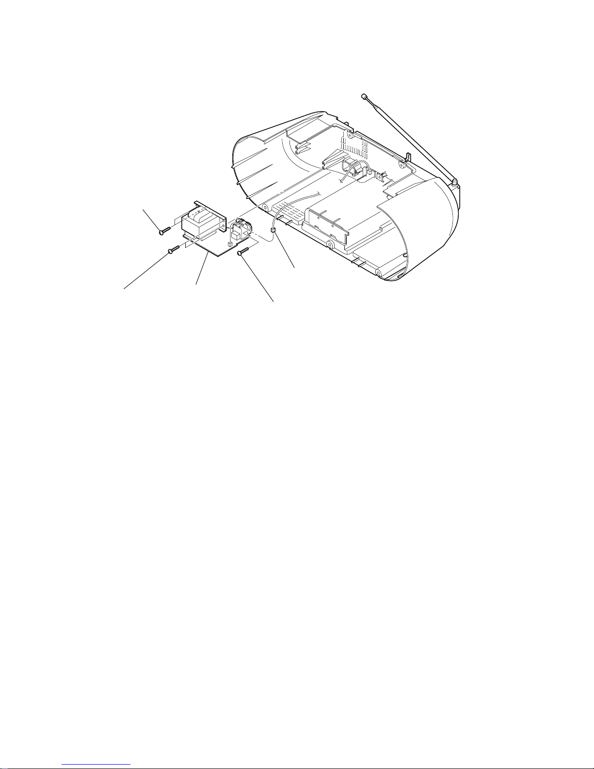
3-11. POWER BOARD
2
screw
(+BV tapping (B2.6))
5
POWER board
1
CN902 (2P)
4
two
screws
(+BV tapping (B2.6))
3
two
screws
(+BV tapping (B2.6))
15
ZS-S2iP
TUNER SECTION 0 dB = 1 µV
• AM Section
Setting:
RADIO BAND•AUTO PRESET button: AM
• FM Section
Setting:
RADIO BAND•AUTO PRESET button: FM
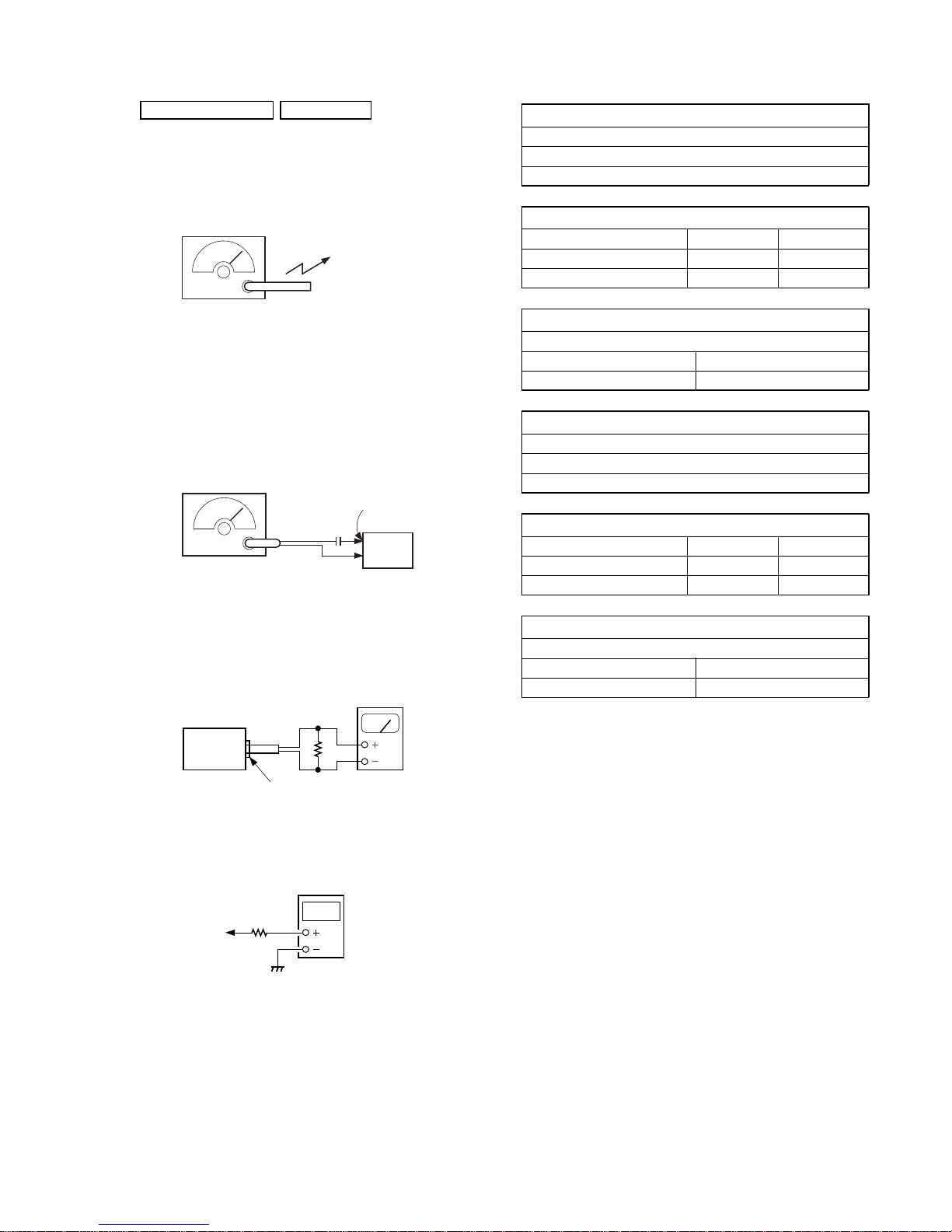
• Connecting Level Meter (FM, AM)
• Connecting Digital Voltmeter (FM, AM)
•Repeat the procedures in each adjustment several times, and the
frequency coverage and tracking adjustments should be finally
done by the trimmer capacitors.
Put the lead-wire
antenna close to
the set.
AM RF signal
generator
30% amplitude
modulation by
400 Hz signal
ANT2
FM RF signal
generator
75 kHz frequency
deviation by 1 kHz signal
output level : as low as possible
0.01
µ
F
set
i
jack (J321)
set
32
Ω
level meter
(range: 0.5–5 V ac
)
digital
voltmeter
100 k
Ω
TP (VT)
AM IF ADJUSTMENT
Adjust for a maximum reading on level meter.
T1
450 kHz
AM FREQUENCY COVERAGE CHECK
Frequency Display 530 kHz 1,710 kHz
Reading on Digital voltmeter 0.8 ± 0.3 V 5.8 ± 0.1 V
Adjustment Part L3 <confirmation>
AM TRACKING ADJUSTMENT
Adjust for a maximum reading on level meter.
ANT1 CT3
620 kHz 1,400 kHz
FM IF ADJUSTMENT
Adjust for a maximum reading on level meter.
L6
10.7 MHz
FM FREQUENCY COVERAGE ADJUSTMENT
Frequency Display 87.5 MHz 108 MHz
Reading on Digital voltmeter 1.5 ± 0.3 V 3.0 ± 0.2 V
Adjustment Part <confirmation> L2
FM TRACKING ADJUSTMENT
Adjust for a maximum reading on level meter.
L1 CT1
87.5 MHz 108 MHz
Adjustment Location: See page 16.
SECTION 4
ELECTRICAL ADJUSTMENTS
16
ZS-S2iP
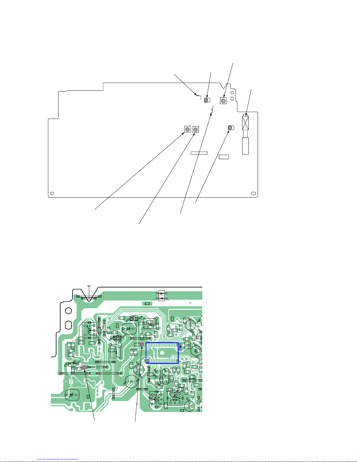
Adjustment Location:
L3: AM FREQUENCY COVERAG
E
ADJUSTMENT
L2: FM FREQUENCY COVERAGE
ADJUSTMENT
CT1: FM TRACKING
ADJUSTMENT
ANT1: AM TRACKING
ADJUSTMENT
CT3: AM TRACKING ADJUSTMENT
L1: FM TRACKING ADJUSTMENT
T1: AM IF ADJUSTMENT
L6: FM IF ADJUSTMENT
CN702
CN701
– MAIN BOARD (Component Side) –
JW232
JW231
JW226
JW219
JW217
JW218
R11
JW224
JW220
JW223
L3
C15
C14
C13
T1
C25
C28
C24
JW209
JW207
IC1
X1
1936
181
C67
C29
R1
R2
D2
C6
C5
L2
D4
D5
R3
C7
R12
R15
C18
C34
R19
C31
JW188
C32
R17
R41
L6
R29
JW189
R270
C46
C17
C42
C41
C40
R27
R9
D1
L1
C3
D3
R5
CT3
CT1
C12
R6
C11
C10
C2
C23
JW208
CF3
CF2
C26
C27
R28
R25
R26
C22
C21
C4
R7
R4
R13
C45
C16
C19
R39
C39
JW105
C30
R10
R16
C37 R18
R20
C33
C1
C9
C70
TP (VT)
TP (GND)
– MAIN BOARD (Conductor Side) –
Test Point:
17
ZS-S2iP
CD SECTION
CD section adjustments are done automatically in this set.
In case of operation check, confirm that focus bias.
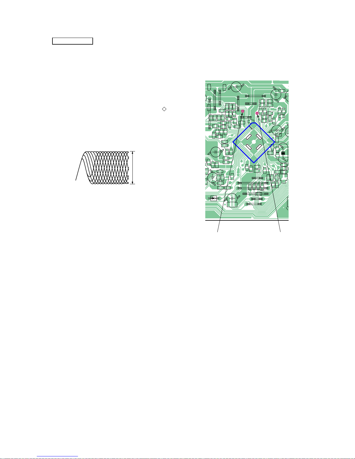
FOCUS BIAS CHECK
1. Connect the oscilloscope between IC701 pin ts and pin 4 (or
TP (RF) and TP (VREF)).
2. Insert the disc (PATD-012 (Tr 15)). (Part No. : 4-225-203-01)
3. Press the N X (CD) button.
4. Confirm that the oscilloscope waveform is as sho wn in the figure
below. (eye pattern)
A good eye pattern means that the diamond shape ( ) in the
center of the waveform can be clearly distinguished.
• RF signal reference waveform (eye pattern)
When observing the eye pattern, set the oscilloscope for AC range
and raise vertical sensitivity.
Test Point:
C716
R727
C717
JC703
R740
C720
JC702
C759
C748
D703
JW200
JW201
C728
JW199
JW198
JW197
JW196
R763
R743
C773
R739
C727
C726
C738
R717
R726
C749
C707
R722
IC701
C711
C708
C705
JW195
R700
C709
R712
R714
R708
JW192
JW193
FB704
C744
C751
C755
C779
C757
C758
R768
C754
C753
C719
C718
R736
R734
R754
C725
C729
C730
R757
R758
R755
R759
R756
C731
R748
Q703
JC705
R761
R762
X701
R760
JC704
R783
R781
JW204
C772
R702
R701
JW203
C706
R721
R707
R705
R706
JW147
JW202
R703
R704
R716
R711
C700
R709
R713
C710
C777
R710
R725
R766
R772
C762
C745
C752
R770
C704
C712
C713
R728
C774
C750
1
152
26 27
13
14
40
39
TP (VREF) TP (RF)
– MAIN BOARD (Conductor Side) –
RF level :
1.7
±
0.2 Vp-p
VOLT/DIV : 50 mV (10 : 1 probe in use)
TIME/DIV : 500 nS
 Loading...