

Sony ZSM-30 Service manual
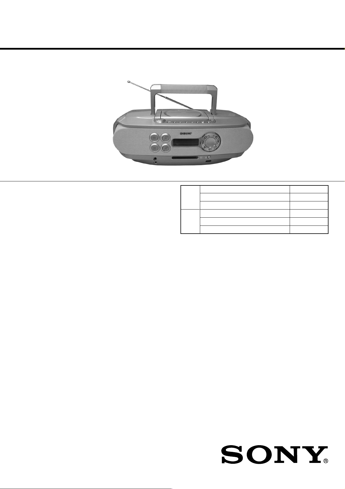
ZS-M30
SERVICE MANUAL
Ver 1.1 2001.04
US and foreign patents licensed from Dolby
Laboratories Licensing Corporation
CD
Section
MD
Section
Australian Model
Model Name Using Similar Mechanism
CD Mechanism Type
Optical Pick-up Name
Model Name Using Similar Mechanism
MD Mechanism Type
Optical Pick-up Name
AEP Model
UK Model
NEW
KSM-213CDP
KSS-213C
NEW
MT-ZSM30-168
KMS-260B
CD player section
System
Compact disc digital audio system
Laser diode properties
Material: GaAlAs
Wave length: 785 nm
Emission duration: Continuous
Laser output: Less than 44.6 µW
(This output is the value measured at a distance of about 200 mm
from the objective lens surface on the optical pick-up block with 7
mm aperture.)
Spindle speed
200 r/min (rpm) to 500 r/min (rpm) (CLV)
Number of programme positions
2
Frequency response
20 - 20 000 Hz +1/–2 dB
Wow and flutter
Below measurable limit
Radio section
Frequency range
FM: 87.5 - 108 MHz
MW:531 - 1,602 kHz (9 kHz step)
530 - 1,610 kHz (10 kHz step)
LW: 153 - 279 kHz
IF FM: 10.7 MHz
MW/LW: 450 kHz
Aerials
FM: Telescopic aerial
MW/LW: External aerial terminals
SPECIFICATIONS
MD player section
System
Minidisc digital audio system
Disc
MiniDisc
Laser diode properties
Material: GaAlAs
Wave length: 785 nm
Emission duration: Continuous
Laser output: Less than 44.6 µW
(This output is the value measured at a distance of about 200 mm
from the objective lens surface on the optical pick-up block with 7
mm aperture.)
Recording/playback time
Stereo recording:
Maximum 80 minutes (with MDW-80)
Monaural recording:
Maximum 160 minutes (with MDW-80)
Revolutions
400 rpm to 900 rpm (CLV)
Error correction
Advanced Cross Interleave Reed Solomon Code (ACIRC)
Sampling frequency
44.1 kHz
Coding
Adaptive Transform Acoustic Coding (ATRAC)
PERSONAL MINIDISC SYSTEM
9-873-011-12
2001D0200-1
© 2001.4
Sony Corporation
Personal Audio Company
Shinagawa Tec Service Manual Production Group

ZS-M30
Modulation system
EFM (Eight-to-Fourteen Modulation)
Number of programme positions
2 stereo programme positions
Frequency response
20 - 20,000 Hz +1/–2 dB
Signal-to-noise ratio
Over 80 dB (during playback)
Wow and flutter
Below measurable limit
General
Speaker
Full-range: 8 cm (3 1 ⁄4 in.) dia., 4 Ω cone type (2)
Panorama sound: 5 cm (2 in.) dia., 12 Ω cone type (2)
Inputs
LINE IN (stereo minijack): Sensitivity 436 mV/870 mV
Outputs
Headphones jack (stereo minijack) (1):
For 32 Ωimpedance headphones
Maximum power output
Full-range: 8 W
Panorama sound: 3.4 W
TABLE OF CONTENTS
Specifications ........................................................................... 1
1. SERVICING NOTE
1-1. Notes on Handling the Optical Pick-up Block or
Base Unit ............................................................................ 3
1-2. Notes on Laser Diode Emission Check .............................. 3
1-3. Notes on Chip Component Replacement ........................... 3
1-4. Flexible Circuit Board Repairing ....................................... 3
1-5. Chuck Plate Jig on Repairing ............................................. 3
1-6. Checking the Laser Diode and Focus Search Operation .... 3
1-7. Checks Prior to Parts Replacement and Adjustments
(for MD Section) ............................................................... 4
2. GENERAL
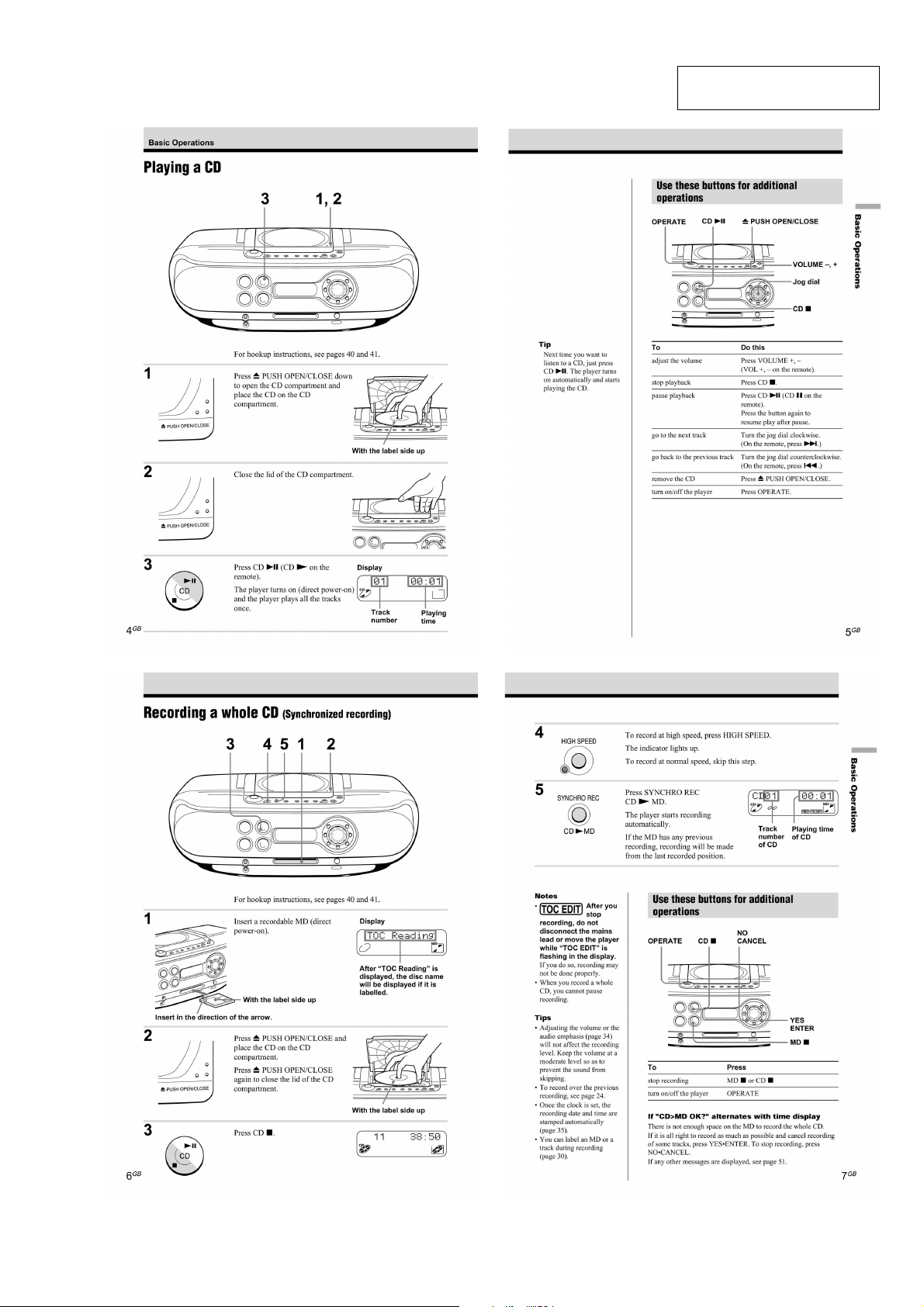
Playing a CD ...................................................................... 5
Recording a Whole CD (Synchronized Recording)........... 5
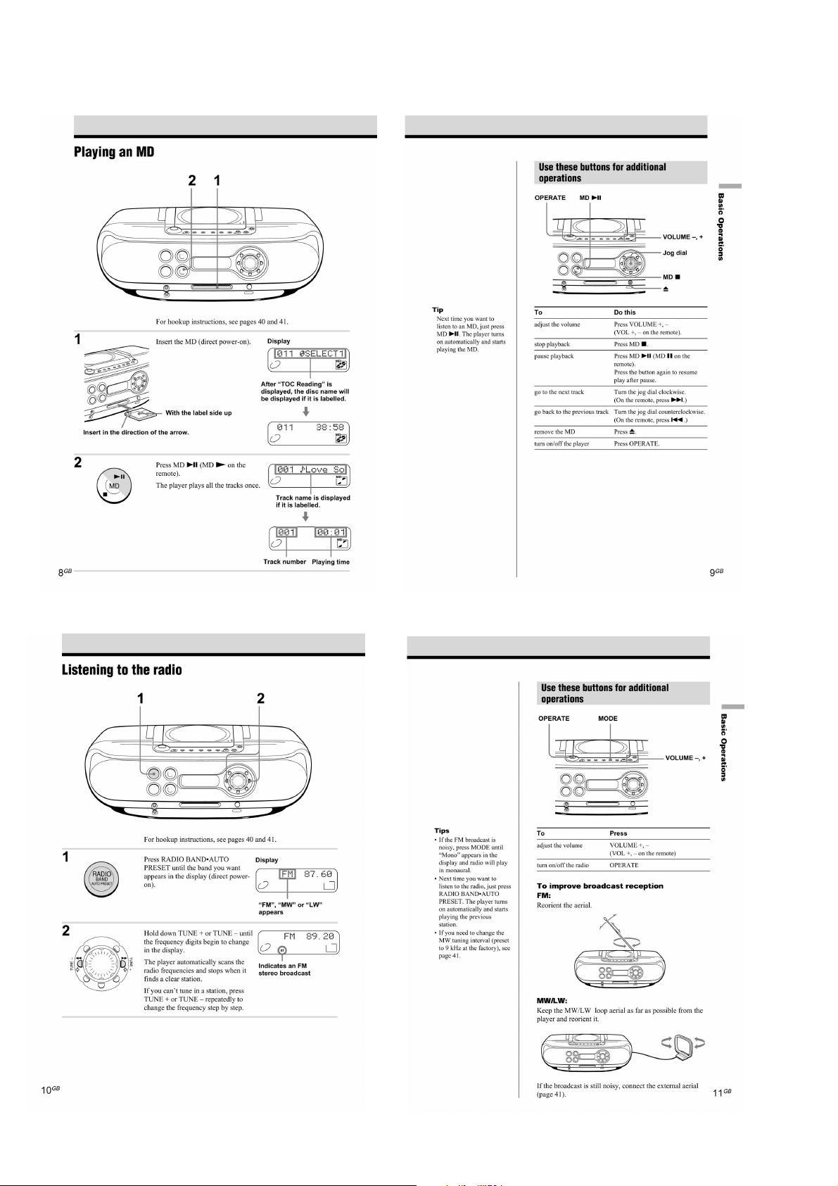
Playing an MD ................................................................... 6
Listening to the Radio ........................................................ 6
3. DISASSEMBLY
3-1. Cabinet (Rear), Cabinet (Front) ......................................... 7
3-2. BATT (B) Board, BATT (A) Board, Power Board ............. 7
3-3. Cabinet (Upper) ASSY....................................................... 8
3-4. Main Board, LCD Board .................................................... 8
3-5. CD Board ........................................................................... 9
3-6. Top Board ........................................................................... 9
3-7. Tuner Board ........................................................................ 9
3-8. MD Block ASSY.............................................................. 10
3-9. SW (L) Board, Jack Board, SW (R) Board ...................... 10
3-10. MD Board ...................................................................... 11
3-11. REC Board, DETECT Board ......................................... 11
3-12. Over Write Head (HR901), MD Optical Pick-up,
D SW Board ................................................................... 12
Power requirements
For personal minidisc system:
230 V AC, 50 Hz
For back-up memory:
4.5 V DC, 3 R6 (size AA) batteries
For remote control:
3 V DC, 2 R6 (size AA) batteries
Power consumption
26 W
Dimensions (incl.projecting parts)
approx. 475 X 165.5 X 249 mm (w/h/d)
(18 3/4 X 6 5 ⁄8 X 9 7/8 inches )
Mass
approx. 4.6 kg (10 lb. 2 oz)
Supplied accessories
Mains lead (1)
Remote control (1)
MW/LW loop aerial (1)
AV connecting cord (1)
Audio connecting cord (1)
Design and specifications are subject to change without
notice.
5. ELECTRICAL ADJUSTMENT
5-1. Tuner Section ................................................................... 17
5-2. MD section ....................................................................... 19
5-3. CD section ........................................................................ 25
6. DIAGRAMS
6-1. IC Pin Function Descriptions ........................................... 28
6-2. Block Diagrams (1/4) ....................................................... 37
6-3. Block Diagrams (2/4) ....................................................... 38
6-4. Block Diagrams (3/4) ....................................................... 39
6-5. Block Diagrams (4/4) ....................................................... 40
6-6. Printed Wiring Boards -Main Section-............................. 41
6-7. Schematic Diagram -Main Section (1/3)- ........................ 42
6-8. Schematic Diagram -Main Section (2/3)- ........................ 43
6-9. Schematic Diagram -Main Section (3/3)- ........................ 44
6-10. Printed Wiring Boards -Power Section- ......................... 45
6-11. Printed Wiring Boards -Tuner Section- .......................... 46
6-12. Schematic Diagram -Tuner Section- .............................. 47
6-13. Printed Wiring Boards -Control Section- ....................... 48
6-14. Schematic Diagram -Control Section- ........................... 49
6-15. Printed Wiring Boards -CD Section- .............................. 50
6-16. Schematic Diagram -CD Section- .................................. 51
6-17. Printed Wiring Boards -MD Section- ............................. 52
6-18. Schematic Diagram -MD Section (1/2)- ........................ 53
6-19. Schematic Diagram -MD Section (2/2)- ........................ 54
7. EXPLODED VIEWS
7-1. Rear Cabinet Section ........................................................ 64
7-2. Front Cabinet Section ....................................................... 65
7-3. Upper Cabinet Section ..................................................... 66
7-4. Optical Pick-up Section.................................................... 67
7-5. MD Section -1 .................................................................. 68
7-6. MD Section -2 .................................................................. 69
4. TEST MODE
4-1. MD Section ...................................................................... 13
4-2. Section the Test Mode ...................................................... 13
4-3. Releasing the Test Mode .................................................. 13
4-4. Basic Operations of the Test Mode .................................. 13
4-5. Selecting the Test Mode ................................................... 14
4-6. Functions of Other Buttons .............................................. 16
4-7. Test Mode Displays .......................................................... 16
4-8. Meanings of Other Displays............................................. 16
2
8. ELECTRICAL PARTS LIST .................................... 70
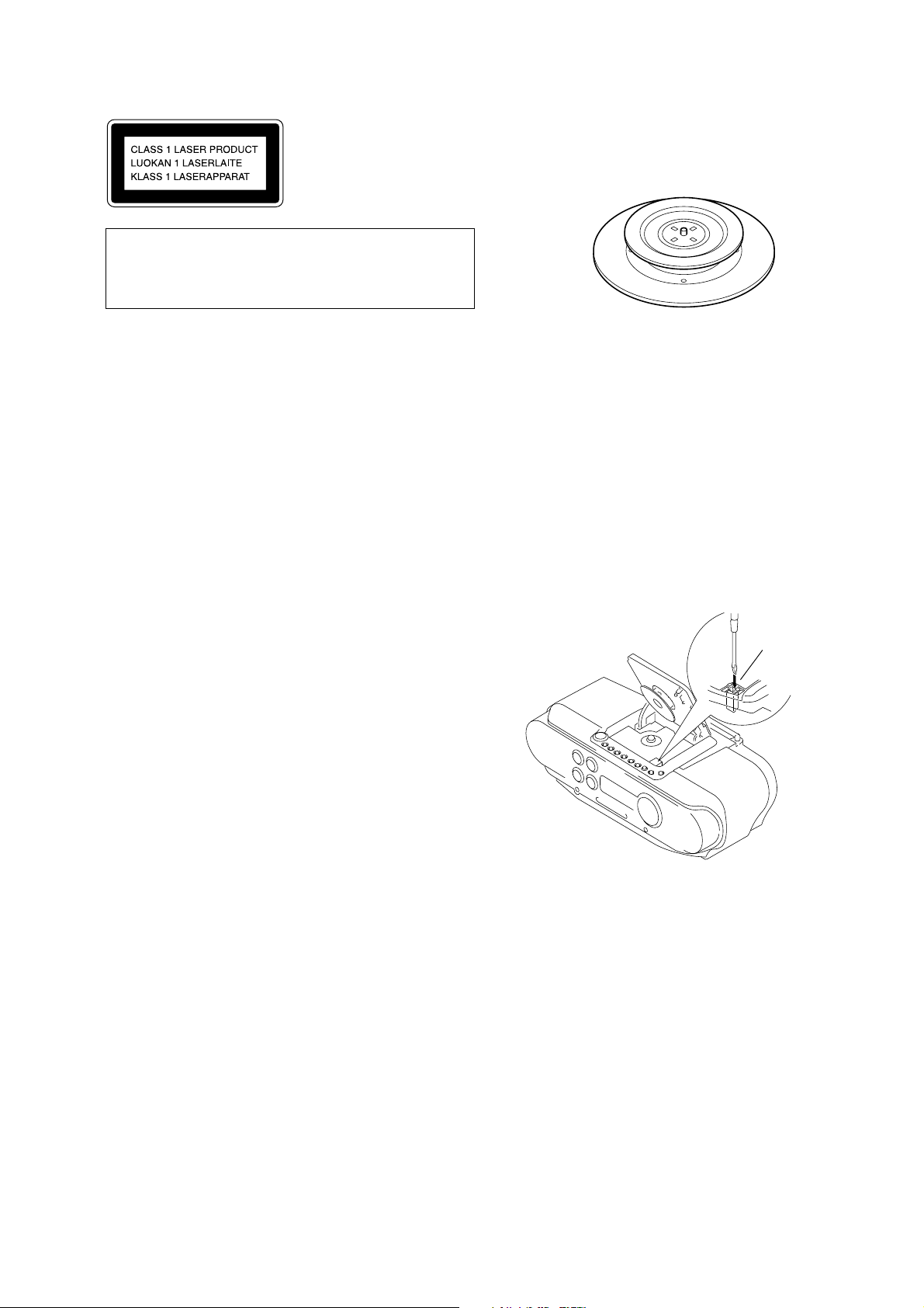
Insert a precision
screw driver and push
SWITCH (S701)
SECTION 1
SERVICE NOTE
ZS-M30
This Compact Disc player
is classified as a CLASS 1
LASER product.
The CLASS 1 LASER
PRODUCT label is located
on the bottom exterior.
CAUTION
Use of controls or adjustments or performance of proceduresother than those specified herein may result in hazardous radiation exposure.
1-1. NOTES ON HANDLING THE OPTICAL PICK-UP
BLOCK OR BASE UNIT
The laser diode in the optical pick-up block may suffer electrostatic break-down because of the potential difference generated
by the charged electrostatic load, etc. on clothing and the human
body.
During repair, pay attention to electrostatic break-down and also
use the procedure in the printed matter which is included in the
repair parts.
The flexible board is easily damaged and should be handled
with care.
1-2. NOTES ON LASER DIODE EMISSION CHECK
The laser beam on this model is concentrated so as to be focused
on the disc reflective surface by the objective lens in the optical
pick-up block. Therefore, when checking the laser diode emission,observe from more than 30 cm away from the objectivelens.
1-5. CHUCK PLATE JIG ON REPAIRING
On repairing CD section, playing a disc without the CD lid, use
Chuck Plate Jig.
• Code number of Chuck Plate Jig: X-4918-255-1
1-6. CHECKING THE LASER DIODE AND FOCUS
SEARCH OPERATION
1. Turn on the POWER and open the CD cover.
2. As shown below, push S701 (CD DOOR) with a screwdriver or
other tool.
3. Press the CD button.
4. Check the objective lens to make sure that the laser diode is
emitting light. If not so, the auto power control circuit or
optical pickup would be damaged.
Verify that the objective lens moves vertically three times for
focus search.
1-3. NOTES ON CHIP COMPONENT REPLACEMENT
• Never reuse a disconnected chip component.
• Notice that the minus side of a tantalum capacitor may be damaged by heat.
1-4. FLEXIBLE CIRCUIT BOARD REPAIRING
• Keep the temperature of the soldering iron around 270 °C dur-
ing repairing.
• Do not touch the soldering iron on the same conductor of the
circuit board (within 3 times).
• Be careful not to apply force on the conductor when soldering
or unsoldering.
SAFETY-RELATED COMPONENT WARNING!!
COMPONENTS IDENTIFIED BY MARK 0 OR DOTTED
LINE
WITH MARK 0 ON THE SCHEMATIC DIAGRAMS AND IN
THE PARTS LIST ARE CRITICAL TO SAFE OPERATION.
REPLACE THESE COMPONENTS WITH SONY PARTS
WHOSE
PART NUMBERS APPEAR AS SHOWN IN THIS MANUAL
OR IN SUPPLEMENTS PUBLISHED BY SONY.
3

ZS-M30
1-7. CHECKS PRIOR TO PARTS REPLACEMENT AND ADJUSTMENTS (FOR MD SECTION)
Before performing repairs, perform the following checks to determine the faulty locations up to a certain extent.
Details of the procedures are described in “5 Electrical Adjustments”
Laser power check
Focus power check
C PLAY check
Self-recording/playback
check
Criteria for Determination
(Unsatisfactory if specified value is not satisfied)
• 0.9 mW power
Specified value : 0.80 to 0.96 mW
• 7.0 mW power
Specified value : 6.8 to 7.2 mW
lop (at 7mW)
• Labeled on the optical pickup
Iop value ± 10%
• Error rate check
Specified value : For points a and b
C1 error : About 200
ADER : Below 2
Point C
C1 error :Below 50
AD error :Below 2
• Error rate check
Specified value:
a. When using test disc (MDW-74/AU-1)
C1 error : Below 80
ADER : Below 2
b. When using check disc (TDYS-1)
C1 error : Below 50
• CPLAY error rate check
Specified value:
C1 error : Below 80
ADER : Below 2
• Clean the optical pick-up
• Adjust again
• Replace the optical pick-up
• Replace the optical pick-up
• Replace the optical pick-up
• Replace the optical pick-up
If always unsatisfactory:
• Replace the overwrite head
• Check for disconnection of the circuits around the
overwrite head
If occasionally unsatisfactory:
• Check if the overwrite head is distorted
• Check the mechanism around the sled
Measure if unsatisfactory:
Note:
The criteria for determination above is intended merely to determine if satisfactory or not, and does not serve as the specified value for
adjustments.
When performing adjustments, use the specified values for adjustments.
4
SECTION 2
GENERAL
ZS-M30
This section is extracted from
instruction manual.
5
ZS-M30
6
DISASSEMBLY
)
r
The equipment can be removed using the following procedure.
ZS-M30
SECTION 3
Cabinet (rear)
Set
Cabinet (front)
BATT (B) board, BATT (A) board, power board
Main board,
LCD board
Cabinet
(upper)
ASSY
MD block
ASSY
SW (L) board,
Tuner
board
jack board,
SW (R) board
Note : Follow the disassembly procedure in the numerical order given.
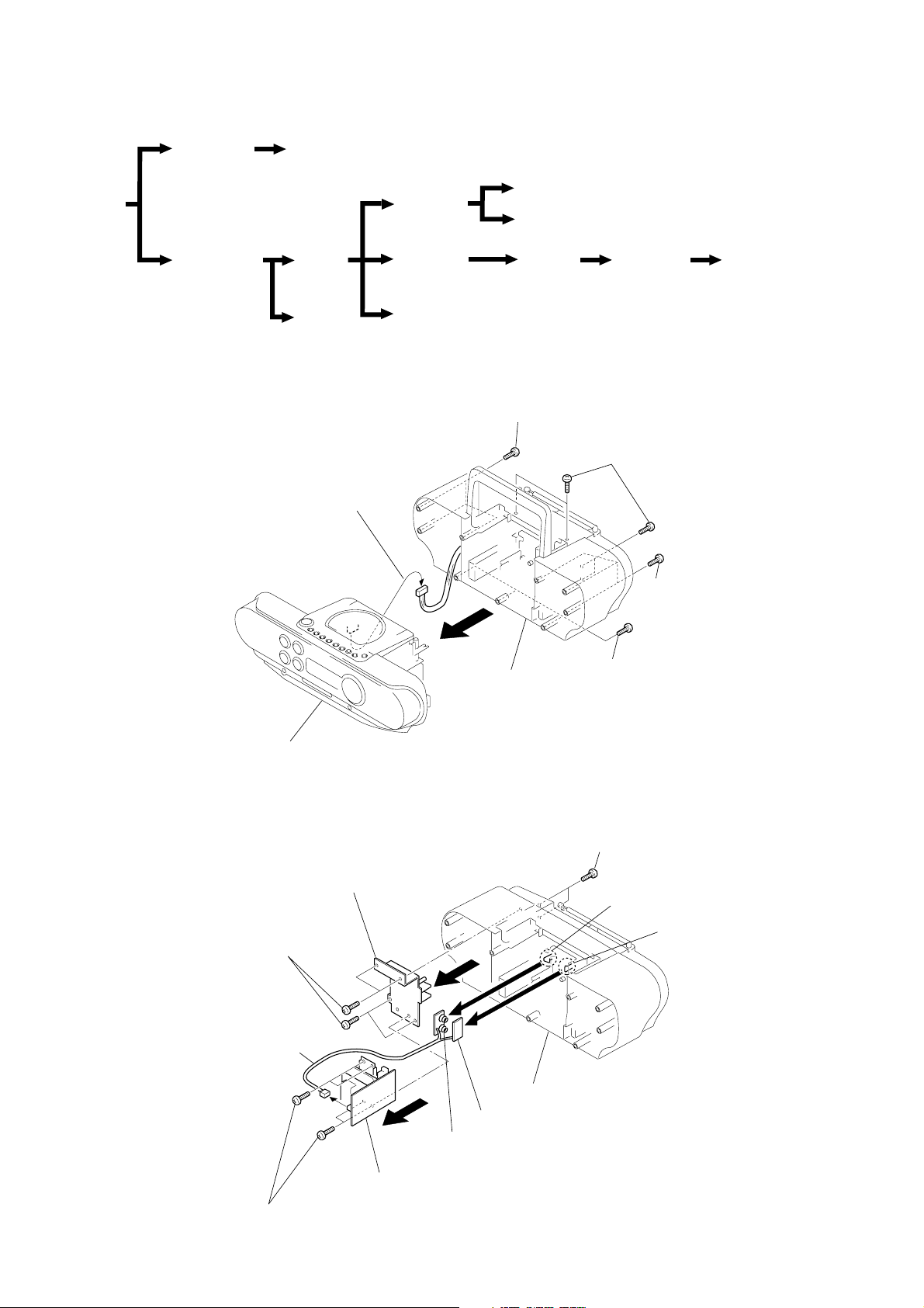
3-1. CABINET (REAR), CABINET (FRONT)
4
Main board
CN801
CD board
TOP board
MD board
1
Screws (+BVTP 3 X 14)
REC board,
detect board
2
(+BVTP 3 X 12) (silver
Screws
1
Screws
(+BVTP 3 X 14)
Over write head (HR901),
MD optical pick-up,
D SW board
3
Cabinet (rear)
Cabinet (front)
3-2. BATT (B) BOARD, BATT (A) BOARD, POWER BOARD
Chissis, transformer
6
Screws (+BVTP 3 X 10)
0
CN902
7
2
4
2
Screws
(+BVTP 3 X 12) (silver)
5
Screws (+BVTP 3 X 12) (silver)
1
Claw
3
Claw
Power board
8
Screws (+BVTP 3 X 10)
9
BATT (A) board
BATT (B) board
Cabinet (rear)
7
ZS-M30
)
)
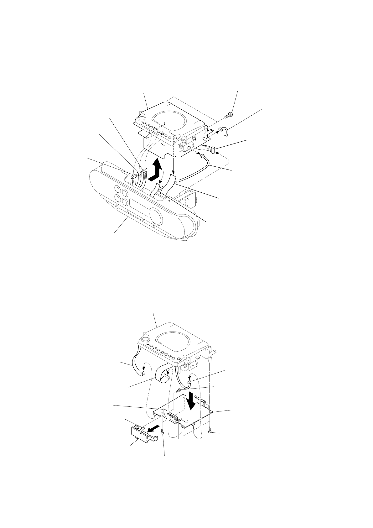
3-3. CABINET (UPPER) ASSY
6
Main board
(CN301)
7
Main board
(CN302)
8
Main board
(CN303)
Cabinet (upper) ASSY
9
1
Screws (+BVTP 3 X 10
2
CN810
3
Tuner board
(CN1)
4
CD board (CN703)
Cabinet (front)
3-4. MAIN BOARD, LCD BOARD
1
Wire,parallel (6 core)
Main board (CN803)
2
Wire,parallel (19 core)
Main board (CN808)
Cabinet (upper) ASSY
5
Wire,parallel (22 core)
Main board (CN807)
0
Wire,parallel (8 core)
SW (R) board (CN402)
3
Main board (CN805)
7
Screws (+BVTP 3 X 10)
0
LCD board
6
LCD board (CN404)
LCD1
8
9
Remove solder (7 places)
4
Screws (+BVTP 3 X 10)
5
Main board
4
Screws (+BVTP 3 X 10
8
3-5. CD BOARD
)
)
Cabinet (upper) ASSY
2
Wire,Parallel (16 core
(CN701)
ZS-M30
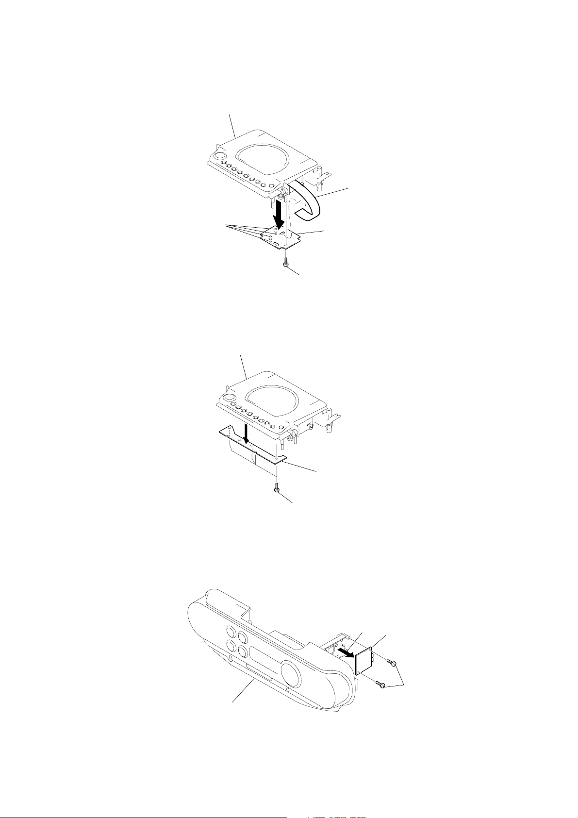
3-6. TOP BOARD
3
Remove solder
(4 places)
4
Cabinet (upper) ASSY
2
CD board
1
Screw (+P 2 X 6)
Top board
3-7. TUNER BOARD
Cabinet (front)
1
Screws (+BVTP 2.6 X 10)
2
Tuner board
1
Screws (+BVTP 3 X 10
9
ZS-M30
)
)
3-8. MD BLOCK ASSY
1
Screws (+BVTP 3 X10)
2
3
Screws (+BVTT 2.6 X 6)
4
1
MD block ASSY
(MT-ZSM30-168)
Chassis (TU)
Screws (+BVTP3 X10
Cabinet (front)
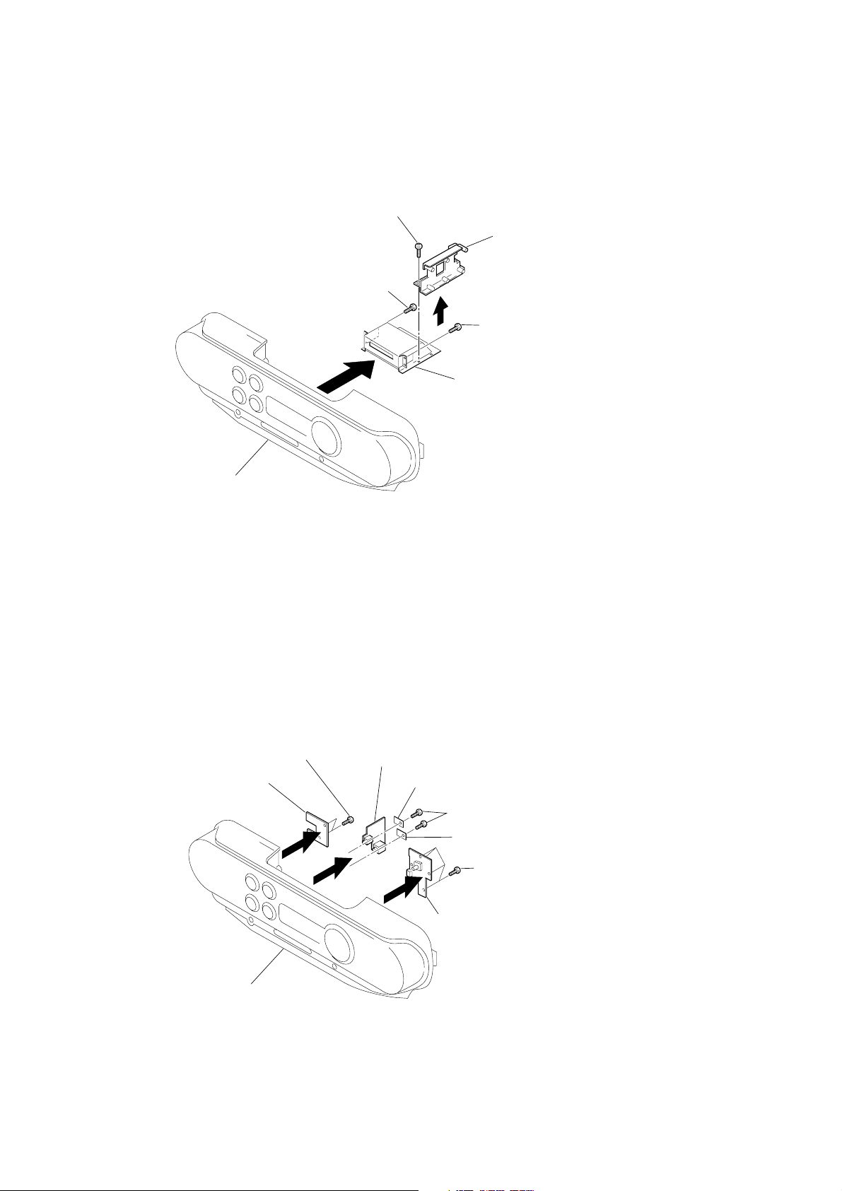
3-9. SW (L) BOARD, JACK BOARD, SW (R) BOARD
1
Screws (+BVTP 2.6 X 10)
SW (L) board
2
4
Jack board
Retainer (A)
6
3
Screws (+BVTP 3 X 10)
Retainer (B)
5
Screws (+BVTP 2.6 X 10
SW (R) board
10
Cabinet (front)
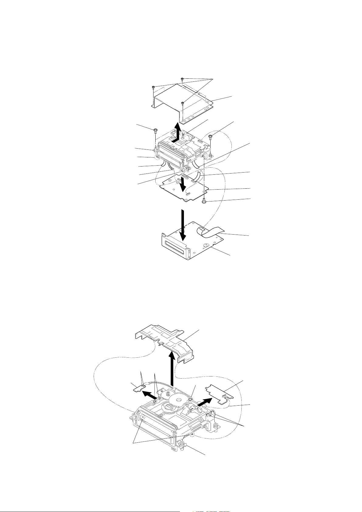
3-10. MD BOARD
qa
4
Screws, MD fitting
MT-ZSM30-168
8
Claw
Wire,Parallel (7 core)
qs
CN601 (2pin)
8
Claw
2
9
1
Screws (+BVTP 2.6 X 5)
Case (MD upper) shield
8
Claw
4
Screws, MD fitting
0
Op flexible board
6
Wire,parallel (9 core)
REC board (CN505)
MD board
ZS-M30
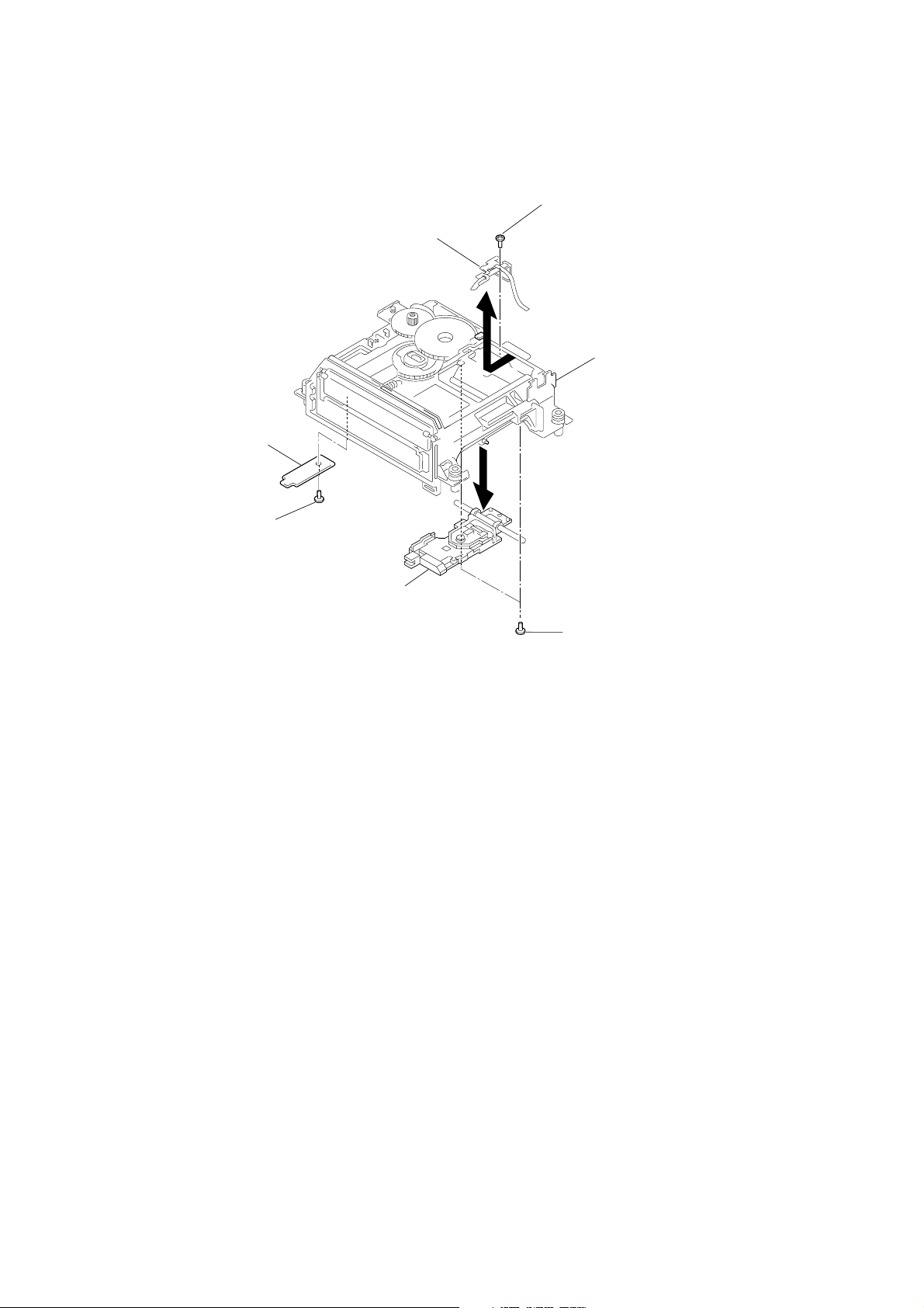
3-11. REC BOARD, DETECT BOARD
8
Remove solder
(2 places)
DETECT board
6
Claws
5
5
2
Slider
Claw
7
Screws (+P 2.6 X 2.5)
3
Wire,parallel (22 core)
Main board (CN807)
Case (MD lower) shield
REC board
4
Move slider away from pin.
7
3
Chassis
1
Over write head flexible board
(CN504)
2
Claws
11
ZS-M30
)
3-12. OVER WRITE HEAD (HR901), MD OPTICAL PICK-UP, D SW BOARD
1
Over write head
(HR901)
4
6
D SW board
3
Screw (+P 1.7X2.5)
Chassis
5
Screws (1.4 X 2)
MD optical pick-up
(KMS-260B)
2
Screws (+P 1.4 X 3.5
12

ZS-M30
SECTION 4
TEST MODE
Refer to “5. ELECTRICAL ADJUSTMENT” for the test mode of CD section.
4-1. MD SECTION
1. PRECAUTIONS FOR USE OF TEST MODE
• As loading related operations will be performed regardless of the test mode operations being performed, be sure to check that the disc is
stopped before setting and removing it.
Even if the Z (MD EJECT) button is pressed while the disc is rotating during continuous playback, continuous recording, etc., the disc
will not stop rotating.
Therefore, it will be ejected while rotating.
Be sure to press the Z (MD EJECT) button after pressing the NO/CANCEL button and the rotation of disc is stopped.
1-1. Recording laser emission mode and operating buttons
• Continuous recording mode (CREC MODE)
• Laser power check mode (LDPWR CHECK)
• Laser power adjustment mode (LDPWR ADJUST)
• When pressing the YES/ENTER button.
4-2. SETTING THE TEST MODE
1. Set to standby state.
2. Press and hold the YES/ENTER button then press MD u t x t u t x .
4-3. RELEASING THE TEST MODE
Remove the power cord to release the test mode.
4-4. BASIC OPERATIONS OF THE TEST MODE
All operations are performed with the following buttons: jogdial . , > , YES/ENTER and NO/CANSEL .
The functions of these buttons are as follows.
Function name Function
JOG ( > ) Proceeds the parameter/mode change.
JOG ( . ) Returns to the parameter/mode change.
YES/ENTER Goes ahead. Determines the setting/selection.
NO/CANCEL Suspends.
13
ZS-M30
4-5. SELECTING THE TEST MODE
There are 9 types of test modes as shown below. The groups can be switched by turn the jog dial. After selecting the
group to be used, press the YES/ENTER button. After setting a certain group, turn the jog dial between these modes.
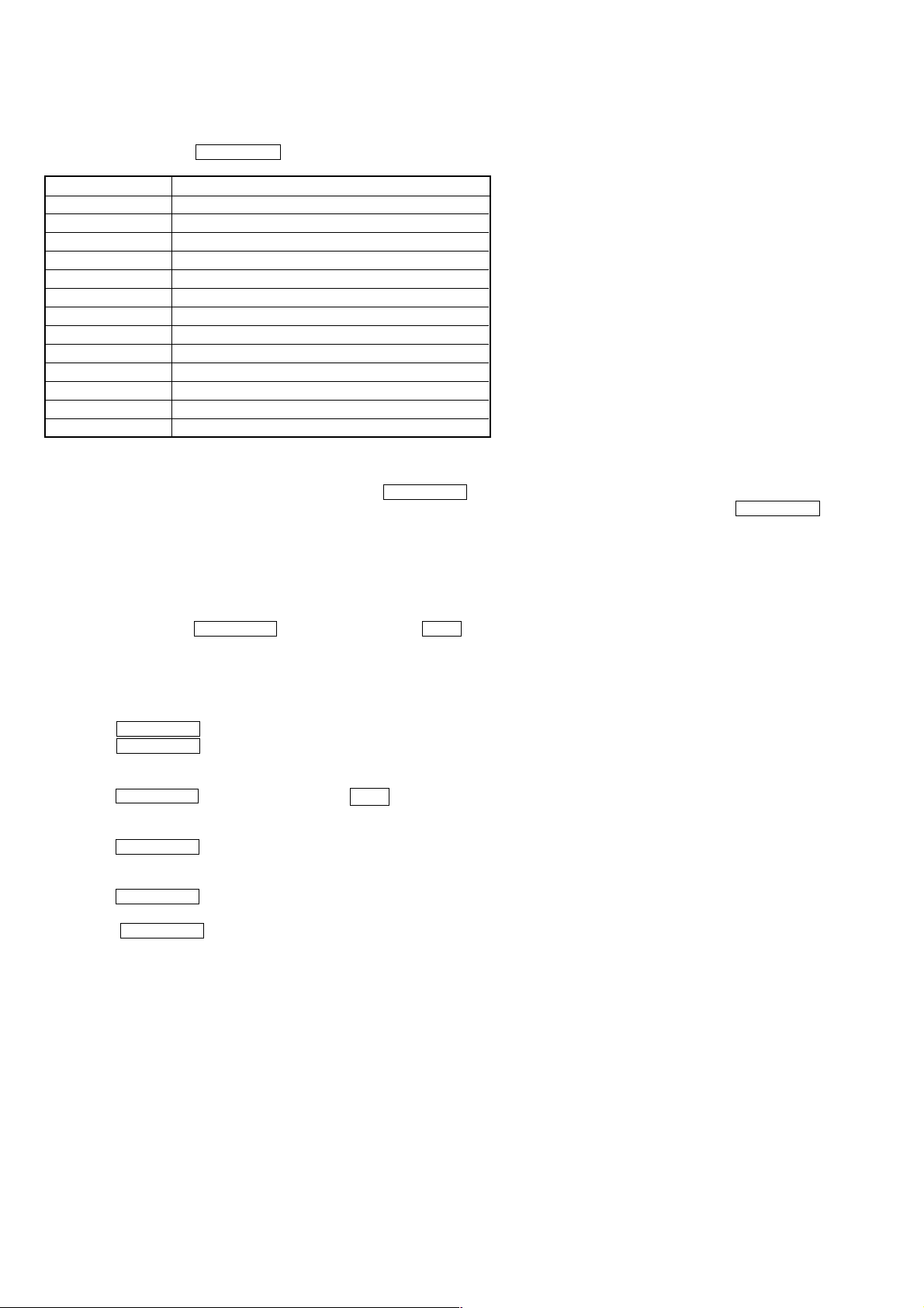
Display Contents
TEMP ADJUST Temperature compensation offset adjustment
LDPWR ADJUST Laser power adjustment
LDPWR CHECK Laser power check
LOAD CHECK load check
S CURVE CHECK S curve check
EFBAL ADJUST EF balance adjustment
FBIAS ADJUST Focus bias adjustment
FBIAS CHECK Focus bias check
CPLAY MODE Continuous playback mode
CREC MODE Continuous recording mode
DETRK CHECK Detrack check
LOAD AGING Load aging
EEP MODE Non-volatile memory control
• For details of each adjustment mode, refer to “5. Electrical Adjustments”.
• If a different mode has been selected by mistake, press the NO/CANCEL button to release that mode.
• EEP MODE is not used for servicing and therefore are not described in detail. If these modes are set accidentally, press the NO/CANCEL
button to release the mode immediately. Be especially careful this mode will overwrite the non-volatile memory and reset it, and as a
result, the unit will not operate normally.
•When selecting test mode, usually the message “TEMP ADJUST” appears. In two rare cases, however, another message may be shown.
1. After conclusion of automatic temperature compensation (starting from display “TEMP = 00”), the message “Disc Insert” appears.
2. The message “Disc Insert” is displayed right form the start.
In both cases press the YES/ENTER button while holding the EDIT button, thus displaying “TEMP ADJUST” and entering
normal test mode.
In order to cause “TEMP ADJUST” to be displayed whenever test mode is selected, execute the following steps.
1. Rotate the jog dial until “EEP MODE” is shown.
2. Press the YES/ENTER button to display “EEP READ”.
3. Press the YES/ENTER button to display “EEP XXXX”.
(The first two “X”-marks represent the address, the latter two the value).
4. Rotate the jog dial to set the address to 15.
5. Press the YES/ENTER button while holding the EDIT button.
6. Confirm that the display shows “EEP15XX >XX”.
7. Rotate the jog dial to set the value after the “>”-mark to FF.
8. Press the YES/ENTER button.
9. Confirm that the display shows “Complete”.
10.After that, confirm that the display turns to “EEP READ”.
11.Press the YES/ENTER button.
12.Confirm that the display shows “EEP15FF”.
13.Press the NO/CANCEL button.
14

4-5-1. Operating the Continuous Playback Mode
1. Entering the continuous playback mode
1 Set the disc in the unit. (Whichever recordable discs or discs for playback only are available)
2 Potate the jog dial and display “CPLAY MODE”.
3 Press the YES/ENTER button to change the display to “CPLAY MID”.
4 When access completes, the display changes to “C1 = AD = ”.
Note: The numbers “ ” displayed show you error rates and ADER.
2. Changing the parts to be played back
1 Press the YES/ENTER button during continuous playback to change the display as below.
CPLAY MID CPLAY OUT CPLAY IN
When pressed another time, the parts to be played back can be moved.
2 When access completes, the display changes to “C1 = AD = ”.
Note: The numbers “ ” displayed show you error rates and ADER.
3. Ending the continuous playback mode
1 Press the NO/CANCEL button. The display will change to “CPLAY MODE”.
2 Press the Z (MD) button and take out the disc.
Note: The playback start addresses for IN, MID, and OUT are as follows.
IN : 40h cluster
MID : 300h cluster
OUT: 700h cluster
ZS-M30
4-5-2. Operating the Continuous Recording Mode (Use only when performing self-recording/palyback check)
1. Entering the continuous recording mode
1 Set a recordable disc in the unit.
2 Rotate the jog dial and display “CRDE MODE”.
3 Press the YES/ENTER button to change the display to “CREC MID”.
4 When access completes, the display changes to “CREC ( )” and “REC ” lights up.
Note: The numbers “ ” displayed shows you the recording position addresses.
2. Changing the parts to be recorded
1 When the YES/ENTER button is pressed during continuous recording, the display changes as below.
CREC MID CREC OUT CREC IN
When pressed another time, the parts to be recorded can be changed. “REC ” goes off.
2 When access completes, the display changes to “CREC (
Note: The numbers “ ” displayed shows you the recording position addresses.
3. Ending the continuous recording mode
1 Press the NO/CANCEL button. The display changes to “CREC MODE” and “REC ” goes off.
2 Press the Z (MD) button and take out the disc.
Note 1: The recording start addresses for IN, MID, and OUT are as follows.
IN : 40h cluster
MID : 300h cluster
OUT: 700h cluster
Note 2: The NO/CANCEL button can be used to stop recording anytime.
Note 3: Do not perform continuous recording for long periods of time above 5 minutes.
Note 4: During continuous recording, be careful not to apply vibration.
)” and “REC ” lights up.
4-5-3. Non-storage memory mode (EEP mode)
This is the mode to read write the contents of the non-volatile storage memory.
This mode is not used for servicing.
If you accidentally enter this mode, exit immediately by pressing the NO/CANCEL button.
15
ZS-M30
4-6. FUNCTIONS OF OTHER BUTTONS
Function Contents
u (MD)
x (MD)
M
m
DISPLAY
Z (MD)
REC/REC MODE
4-7. TEST MODE DISPLAYS
Each time the DISPLAY button is pressed, the display changes in the following order.
1. Mode display
Displays “TEMP ADJUST”, “CPLAYMODE”, etc.
2. Error rate display
Displays the error rate in the following way.
C1 = AD =
C1 = Indicates the C1 error.
AD = Indicates ADER.
3. Address display
The address is displayed as follows. (MO: recordable disc, CD: playback only disc)
Press the REPEAT buttons at the same time to switches between the groove display
and pit display.
h = s = (MO pit and CD)
h = a = (MO groove)
h = Indicates the header address.
s = Indicates the SUBQ address.
a = Indicates the ADIP address.
Sets continuous playback when pressed in the STOP state. When pressed during continuous
playback, the tracking servo turns ON/OFF.
Stops continuous playback and continuous recording.
The sled moves to the outer circumference only when this is pressed.
The sled moves to the inner circumference only when this is pressed.
Switches the displayed contents each time the button is pressed
Ejects the disc
When pressed during continuous playback, switches between recording start stop.
Mode display
Error rate display
Address display
Auto gain display
(Not used in servicing)
IVR display
(Not used in servicing)
Note: “–” is displayed when servo is not imposed.
4. Auto gain display (Not used in servicing)
The auto gain is displayed as follows.
AG F =
5. IVR display (Not used in servicing)
The IVR is displayed as follows.
[ ][ ][ ]
T =
4-8.MEANINGS OF OTHER DISPLAYS
Display
SHUF
PGM
REC
TOC EDIT
TRACK
TIMER
MONO
During continuous playback (CLV: ON)
Tracking servo OFF
Recording mode ON
Contents When Lit When Off
ABCD adjustment completed
Pit
CLV-S
FCS/TRK/AUTO GAIN successful
Contents
STOP (CLV: OFF)
Tracking servo ON
Recording mode OFF
Groove
CLV-A
FCS successful, TRK unsuccessful
16
TUNER BOARD
C27
C10
R5
JC3
C12
R28
C44
Q3
C45
C43
C51
C5
R7
R4
D2
C6
R2
R3
C7
R32
Q2
Q4
R6
C8
C46
C47
C4
L7
C54
C11
R13
C26
R14
C9
R30
D4
D8
D9
D5
R31
D6
D7
JW2
JW7
CT4
JW6
D3
L4
L2
JW10
L5
JW5
Q1
FL1
CT3
L3
CT2
JW4
JW3
JW1
SECTION 5
W
c
r
ELECTRICAL ADJUSTMENTS
ZS-M30
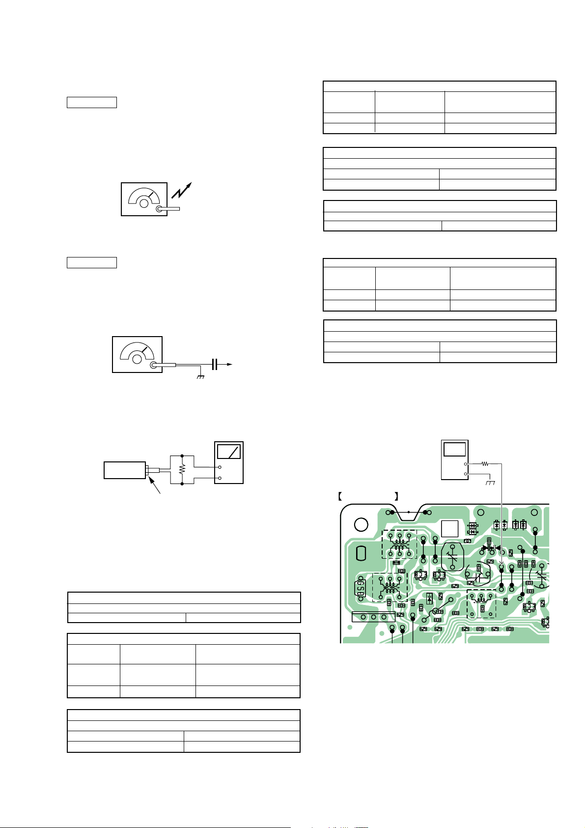
5-1.TUNER SECTION
AM Section
RADIO BAND button : MW or LW
Volume : MIN
AM RF signal
generator
30% amplitude modulation by 400Hz
signal.
Output level : as low as possible
FM Section
RADIO BAND button : FM
Volume : MIN
FM RF signal
generator
22.5kHz frequency deviation by
400Hz signal.
Output level : as low as possible
Put the lead-wire
antenna close to
the supplisd MW/L
loop antenna.
0.01 uF
telescopi
antenna
terminal
LW FREQUENCY COVERAGE ADJUSTMENT
Adjust part Frequency display
reading on digital
voltmeter
CT4 279kHz Adjustment value: 5.4 to 6.0V
Confirmation 153kHz 0.4 to 1.1V
LW TRACKING ADJUSTMENT
Adjust for a maximum reading on level meter.
L 4 162kHz
CT3 261kHz
Adjust for a maximum reading on level meter.
FM FREQUENCY COVERAGE ADJUSTMENT
Adjust part Frequency display
FM IF ADJUSTMENT
L6 10.7MHz
reading on digital
voltmeter
Confirmation 87.5kHz 1.4 to 2.4V
Confirmation 108kHz 2.7 to 3.7V
FM TRACKING ADJUSTMENT
Adjust for a maximum reading on level meter.
L1 87.5MHz
CT1 108MHz
Frequency Coverage Adjustment
Connect Location :
level mete
47K
Ω
set
+
–
LINE OUT
Adjustment Location : Tuner board (See page 18)
• Repeat the procedures in each adjustment several times, and the
frequency coverage and tracking adjustments should be finally
done by the trimmer capacitors.
Adjust for a maximum reading on level meter.
MW FREQUENCY COVERAGE ADJUSTMENT
Adjust part Frequency display
L5 531kHz
Confirmation 1,611kHz
Adjust for a maximum reading on level meter.
L 3 621kHz
CT2 1,404kHz
AM IF ADJUSTMENT
T1 450kHz
reading on digital
voltmeter.
Adjustment value: 1.0V
Standaed value: 0.7 to 1.3V
5.1 to 5.9V
MW TRACKING ADJUSTMENT
(SIDE B)
Digital
voltmeter
+
—
100K
Ω
JW4
(VT)
17
ZS-M30
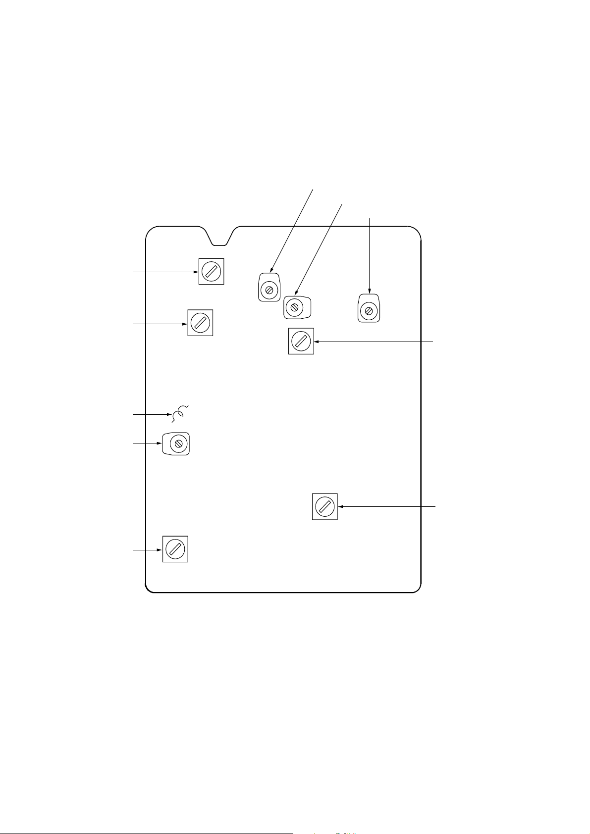
t
Adjustment Location:
L3 : MW Tracking Adjustment
[TUNER BOARD]
(Component side)
CT2 : MW Tracking Adjustment
CT3 : LW Tracking Adjustment
CT4 : LW Frequency Coverage Adjustment
L4 : LW Tracking Adjustment
L1 : FM Tracking Adjustment
CT1 : FM Tracking Adjustment
T1 : AM IF Adjustment
L5 : MW Frequency
Coverage Adjustmen
L6 : FM IF Adjustment
18
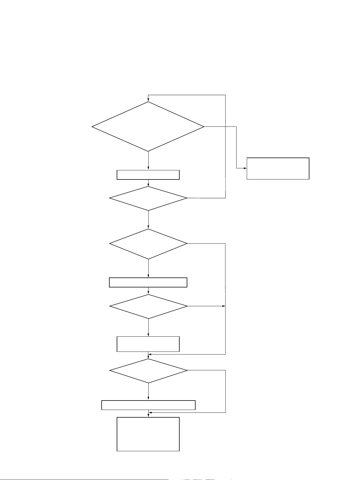
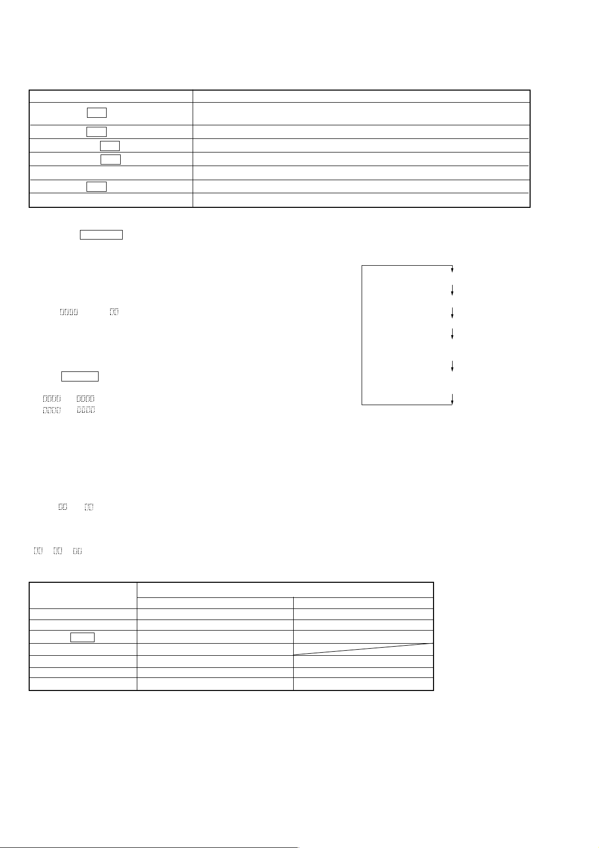
5-2. MD SECTION
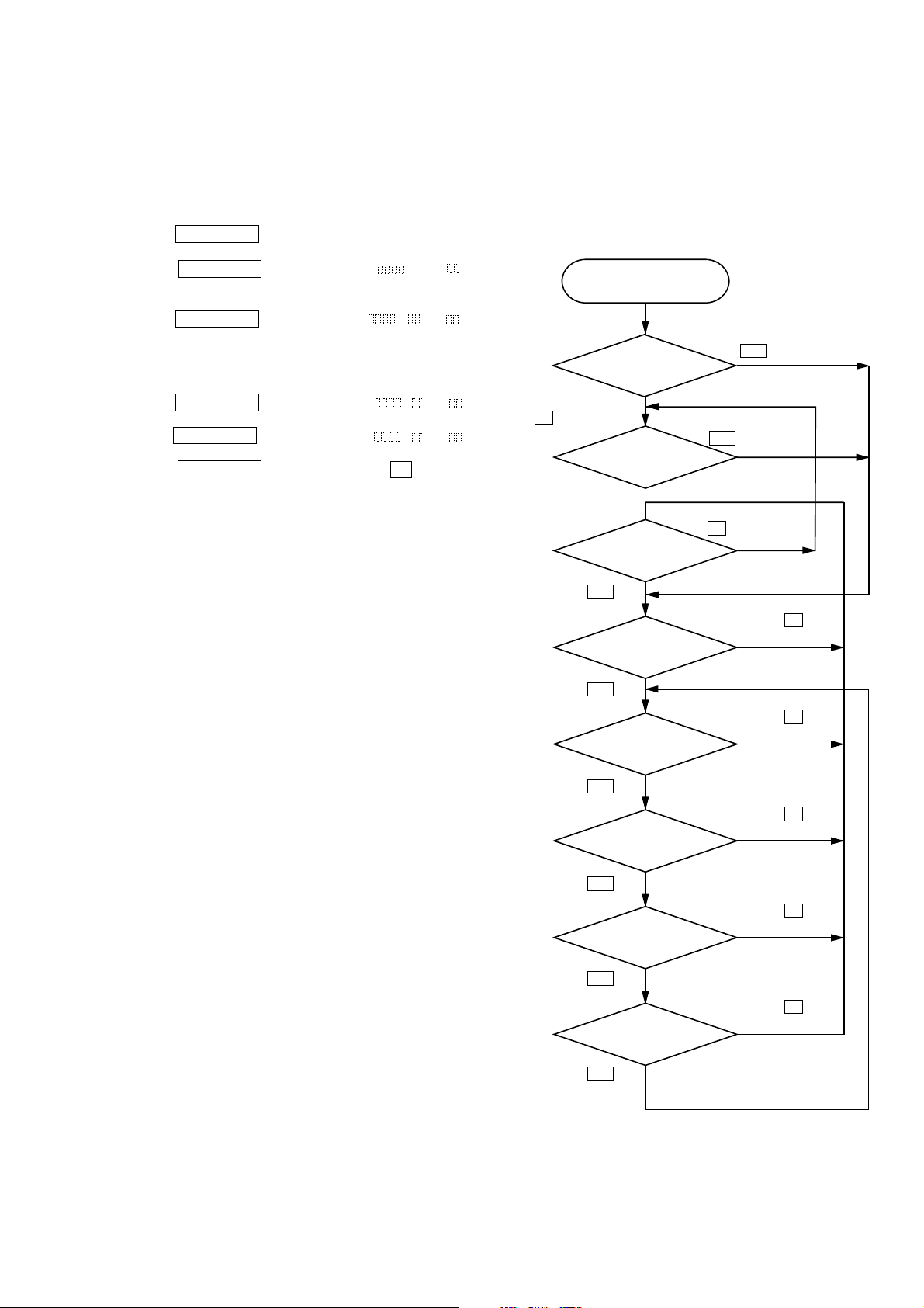
1. PARTS REPLACEMENT AND ADJUSTMENT
• Check and adjust the mechanism deck as follows.
The procedure changes according to the part replaced.
• Laser power check
• Focus bias check
• C PLAY check
• Self-recording/playback check
Parts Replacement and Repair
ZS-M30
• Abbreviation
OP : Optical pick-up
OWH : Overwrite head
OK
NG
Check the sled and spindle
mechanisms.
Other causes can be suspected.
Has the OWH been replaced?
NO
Has OP, IC603, IC502, or
IC504 been replaced?
YES
Initial setting of the adjustment value
Has OP or IC603 been replaced?
YES
IOP information recording
(IOP value labeled on OP)
YES
NO
NO
Has IC603 or D501
been replaced?
YES
Temperature compensation offset adjustment
• Laser power adjustment
• EF balance adjustment
• Focus bias adjustment
• Error rate adjustment
• Focus bias check
• Auto gain adjustment
NO
19
ZS-M30
d
2. PRECAUTIONS FOR CHECKING LASER DIODE
EMISSION
To check the emission of the laser diode during adjustments, never
view directly from the top as this may lose your eye-sight.
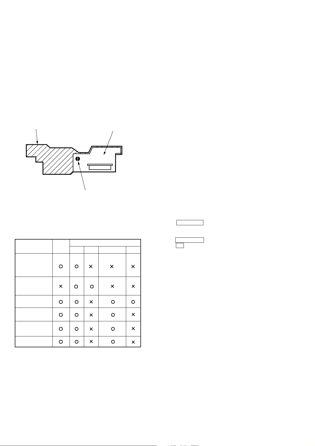
3. PRECAUTIONS FOR USE OF OPTICAL PICK-UP
(KMS-260B)
As the laser diode in the optical pick-up is easily damaged by static
electricity, solder the laser tap of the flexible board when using it.
Before disconnecting the connector, desolder first. Before connectingthe connector, be careful not to remove the solder. Also take
adequate measures to prevent damage by static electricity. Handle
the flexible board with care as it breaks easily.
pick- up
laser tap
flexible boar
Optical pick-up flexible board
4. PRECAUTIONS FOR ADJUSTMENTS
1. When replacing the following parts, perform the adjustments
and checks with in the order shown in the following table.
BD Board
1.
Recording of IOP
information
(Value written in
the pick-up)
2.Temperature
compensation
offset adjustment
3.Laser power
adjustment
4.EF balance
adjustment
Optical
Pick-up
IC603 D501 IC502, IC504 IC506
4. Use the following tools and measuring device.
• Check Disc (MD) TDYS-1
(Part No. 4-963-646-01)
• Test Disc (MDW-74/AU-1) (Part No. 8-892-341-41)
• Laser power meter LPM-8001 (Part No. J-2501-046-A)
or MD Laser power meter 8010S (Part No. J-2501-145-A)
• Oscilloscope (Measure after performing CAL of prove)
• Digital voltmeter
• Thermometer
5. When observing several signals on the oscilloscope, etc., make
sure that VC and ground do not connect inside the oscilloscope.
(VC and ground will become short-circuited)
6. Using the above jig enables the waveform to be checked with-out
the need to solder.
(Refer to Service Note on page 3)
7. As the disc used will affect the adjustment results, make sure
that not dusts nor fingerprints are attached to it.
Laser Power Meter
When performing laser power checks and adjustment (electrical
adjustment), use of the new MD laser power meter 8010S (Part No.
J-2501-145-A) instead of the conventional laser power meter is con-
venient.
It sharply reduces the time and trouble to set the laser power meter
sensor onto the objective lens of optical pick-up.
5. CREATING CONTINUOUSLY-RECORDED DISC
* This disc is used in focus bias adjustment and error rate check.
The following describes how to create a continuous recording
disc.
1. Insert a disc (blank disc) commercially available.
2. Turn the JOG dial to display “CREC MODE”.
3. Press the YES/ENTER button again to display “CREC MID”.
Display “CREC (0300)” and start to recording.
4. Complete recording within 5 minutes.
5. Press the NO/CANCEL button and stop recording.
6. Press the Z (MD) button and remove the disc.
The above has been how to create a continuous recorded data for
the focus bias adjustment/check and MO error rate check.
Note:
• Be careful not to apply vibration during continuous recording.
5.Focus bias
adjustment
6.Error rate check
2. Set the test mode when performing adjustments.
After completing the adjustments, release the test mode.
Perform the adjustments and checks in “group S” of the test
mode.
3. Perform the adjustments to be needed in the order shown.
20
ZS-M30
r
2
)
6. CHECK PRIOR TO REPAIRS
These checks are performed before replacing parts according to
“approximate specifications” to determine the faulty locations. For
details, refer to “Checks Prior to Parts Replacement and Adjustments”(See page 4).
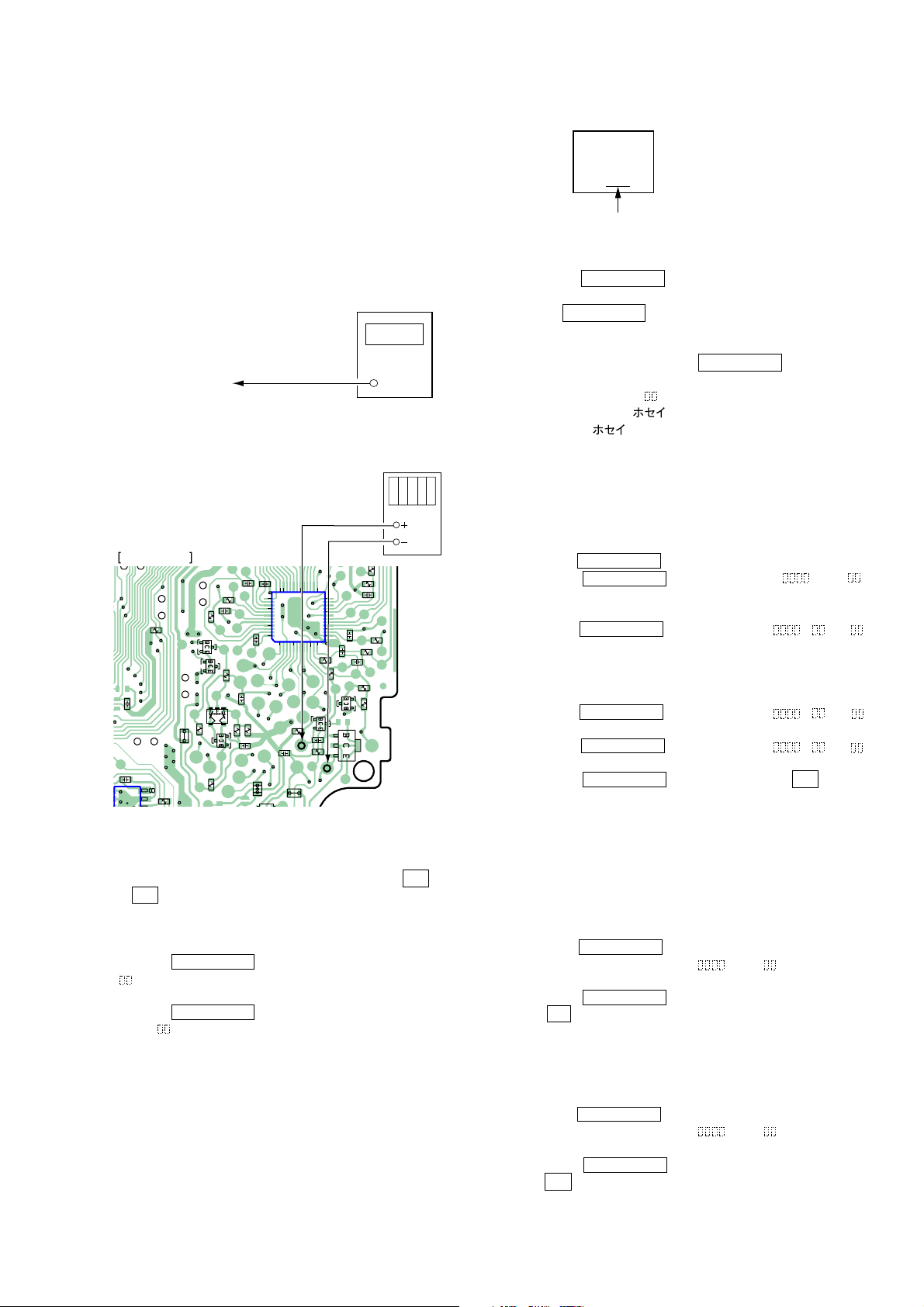
6-1. Laser Power Check
Connection:
laser
power mete
Optical pick-up
objective lens
digital voltmeter
TP502 (I+3V)
TP503 (IOP)
MD BOARD (SIDE B)
R622
C607
L503
C611
R633
Q504
R505
R517
Q502
R508
Q505
R518
Q501
C519
R502
C508
C520
R510
C517
C502
L501
C522
37
40
45
48
R509
C506
36
1
3035
IC502
5
R514
TP502
(I+3V)
L506
R513
1012
Q507
25
C511
R511
(TE)
24
20
15
13
Q503
TP503
(IOP)
R516
Q506
C505
C512
C521
C518
R515
R519
R512
R503
R504
R5
(Optical pick-up label)
KMS260B
27X40
B0825
lOP=82.5 mA in this case
lOP (mA) = Digital voltmeter reading (mV)/3.3 (
Ω
5. Press the NO/CANCEL button to display “LDPWR CHECK”
and stop the laser emission.
(The NO/CANCEL button is effective at all times to stop the
laser emission)
Note 1: After step 4, each time the YES/ENTER button is pressed,
the display will be switched “LD 0.7 mW $ ”,
“LD 6.2 mW $ ”,
and “LD WP $ ”. Nothing needs to be performed
here.( = correction)
6-2. Focus Bias Check
Change the focus bias and check the focus tolerance amount.
Checking Procedure:
1. Load the test disc (MDW-74/AU-1).
2. Turn the JOG dial to display “CPLAY MODE”.
3. Press the YES/ENTER button twice to display “CPLAY MID”.
4. Press the NO/CANCEL button when “C1 =
AD = ”
is displayed.
5. Turn the JOG dial to display “FBIAS CHECK”.
6. Press the YES/ENTER button to display “ / c = ”.
The first four digits indicate the C1 error rate, the two digits
after (( / )) indicate ADER, and the 2 digits after “c =” indicate
the focus bias value.
Check that the C1 error is below 50 and ADER is below 2.
7. Press the YES/ENTER button to display “ / b = ”.
Check that the C1 error is about 200 and ADER is below 2.
8. Press the YES/ENTER button to display “ / a = ”.
Check that the C1 error is about 200 and ADER is below 2.
9. Press the NO/CANCEL button, then press the Z (MD)
button and take out the test disc.
Checking Procedure:
1. Set the laser power meter on the objective lens of the optical
pick-up. (When it cannot be set properly, press the m but-ton
or M button to move the optical pick-up)
Connect the digital voltmeter to TPO 502 (I+3 V) and TP503 (IOP)
on the MD board.
2. Turm the JOG dial to display “LDPWR CHECK”.
3. Press the YES/ENTER button once to display “LD 0.9 mW $
”. Check that the reading of the laser power meter become
0.80 to 0.96 mW.
4. Press the YES/ENTER button once more to display “LD 7.0
mW $ ”. Check that the reading the laser power meter and
digital voltmeter satisfy the specified value.
Specified Value:
Laser power meter reading : 6.8 - 7.2 mW
Digital voltmeter reading : Value on the optical pick-up label
± 10 %
6-3. C PLAY Check
MO Error Rate Check
Checking Procedure:
1. Load the test disc (MDW-74/AU-1).
2. Turn the JOG dial to display “CPLAY MODE”.
3. Press the YES/ENTER button to display “CPLAY MID”.
4. The display changes to “C1 = AD = ”.
5. If the C1 error rate is below 80, check that ADER is below 2.
6. Press the NO/CANCEL button to stop playback, then press
the Z (MD) button and take out the test disc.
CD Error Rate Check
Checking Procedure:
1. Load the check disc (MD) TDYS-1.
2. Turn the JOG dial to display “CPLAY MODE”.
3. Press the YES/ENTER button twice to display “CPLAY MID”.
4. The display changes to “C1 =
AD = ”.
5. Check that the C1 error rate is below 50.
6. Press the NO/CANCEL button to stop playback, then press
the Z (MD) button and take out the check disc.
21
ZS-M30
r
2
6-4. Self-Recording/playback Check
Prepare a continuous recording disc using the unit to be repaired
and check the error rate.
Checking Procedure:
1. Load a recordable disc (blank disc).
2. Turn the JOG dial to display “CREC MODE”.
3. Press the YES/ENTER button to display “CREC MID”.
4. When recording starts, lights up “ REC ” and display “CREC
(@@@@)” (@@@@ is the address).
5. About 1 minute later, press the NO/CANCEL button to
stop continuous recording.
6. Turn the JOG dial to display “CPLAY MODE”.
7. Press the YES/ENTER button to display “CPLAY MID”.
8. “C1 = AD = ” will be displayed.
9. Check that the C1 error becomes below 80 and the ADER below 2.
10.Press the NO/CANCEL button to stop play back, then press
the Z (MD) button and take out the disc.
Note: After the TEST MODE is entered, insert the disc.
7. TEMPERATURE COMPENSATION OFFSET
ADJUSTMENT
Save the temperature data at that time in the non-volatile memory
as 25 °C reference data.
Note:
1. Usually, do not perform this adjustment.
2. Perform this adjustment in an ambient temperature of 22 °C to
28 °C.
Perform it immediately after the power is turned on when the
internal temperature of the unit is the same as the ambient tem
perature of 22 °C to 28 °C.
3. When D501 has been replaced, perform this adjustment after
the tem-perature of this part has become the ambient tempera
ture.
Adjusting Procedure:
1. Turn the JOG dial to display “TEMP ADJUST”.
2. Press the YES/ENTER button to select the “TEMP ADJUST”
mode.
3. “TEMP = ” and the current temperature data will be displayed.
4. To save the data, press the YES/ENTER button.
When not saving the data, press the NO/CANCEL button.
5. When the YES/ENTER button is pressed, “TEMP = SAVE”
will be displayed and turned back to “TEMP ADJUST” display
then. When the NO/CANCEL button is pressed, “TEMP
ADJUST” will be displayed immediately.
Specified Value:
The “TEMP = ” should be within “E0 - EF”, “F0 - FF”, “00 0F”,“10 - 1F” and “20 - 2F”.
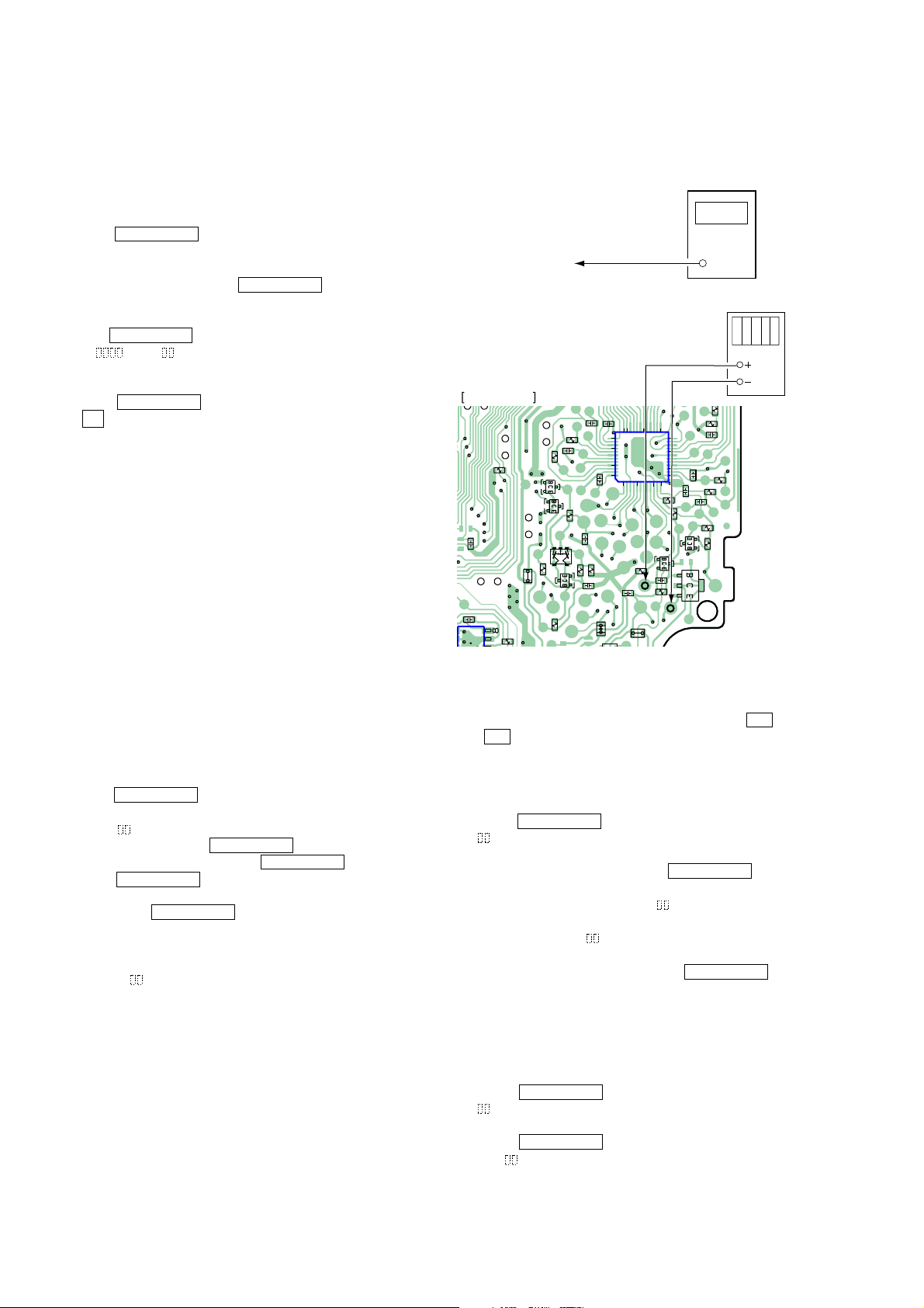
8. LASER POWER ADJUSTMENT
Connection:
laser
power mete
Optical pick-up
objective lens
digital voltmeter
TP502 (I+3V)
TP503 (IOP)
MD BOARD (SIDE B)
R622
C607
L503
C611
R633
Q504
R505
R517
Q502
Q505
R508
R518
Q501
C520
C522
36
37
40
C519
45
48
C517
R502
C502
R510
R509
C508
C506
L501
1
3035
IC502
5
R514
TP502
(I+3V)
L506
R513
Q507
1012
C511
25
R511
(TE)
24
20
15
13
Q503
TP503
(IOP)
R516
Q506
C505
C512
C521
C518
R515
R519
R512
R503
R504
R5
Adjusting Procedure:
1. Set the laser power meter on the objective lens of the optical
pick-up. (When it cannot be set properly, press the m but-ton
or M button to move the optical pick-up)
Connect the digital voltmeter to TP502 (I+3 V) and TP503
(IOP) on the MD board.
2. Turn the JOG dial to display “LDPWR ADJUST”.
(Laser power: For adjustment)
3. Press the YES/ENTER button once to display “LD 0.9 mW
”.
$
4. Turn the JOG dial so that the reading of the laser power meter
becomes 0.85 to 0.91 mW. Press the YES/ENTER button after
setting the range knob of the laser power meter, and save the
adjustment results. (“LD SAVE $ ” will be displayed for a
moment)
5. Then “LD 7.0 mW $ ” will be displayed.
6. Turn the JOG dial and adjust so that the reading on the laser
power meter is 6.9 to 7.1 mW. Press the YES/ENTER button to
save the setting.
Note: Do not perform the emission with 7.0 mW more than 15 sec
onds continuously.
22
7. Turn the JOG dial to display “LDPWR CHECK”.
8. Press the YES/ENTER button once to display “LD 0.9mW
$ ”. Check that the reading of the laser power meter become
0.85 to 0.91 mW.
9. Press the YES/ENTER button once more to display “LD 7.0
mW $ ”. Check that the reading the laser power meter and
digital voltmeter satisfy the specified value.
Note down the digital voltmeter reading value.
ZS-M30
)
R542
4
R542
4
A
B
A
B
Specified Value:
Laser power meter reading : 7.0 ± 0.2 mW
Digital voltmeter reading : Value on the optical pick-up label
± 10%
(Optical pick-up label)
KMS260B
27X40
B0825
lOP=82.5 mA in this case
lOP (mA) = Digital voltmeter reading (mV)/3.3 (
Ω
10. Press the NO/CANCEL button to display “LDPWR
CHECK” and stop the laser emission.
(The NO/CANCEL button is effective at all times to stop
the laser emission)
Note 1: After step 9, each time the YES/ENTER button is pressed, the
display will be switched “LD 0.7 mW $ ”, “LD 6.2 mW $ ”,
and “LD WP $ ”. Nothing needs to be performed here.
( = correction)
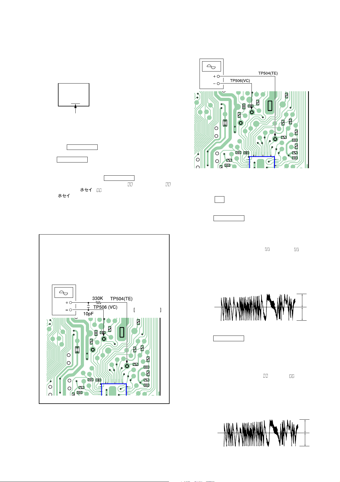
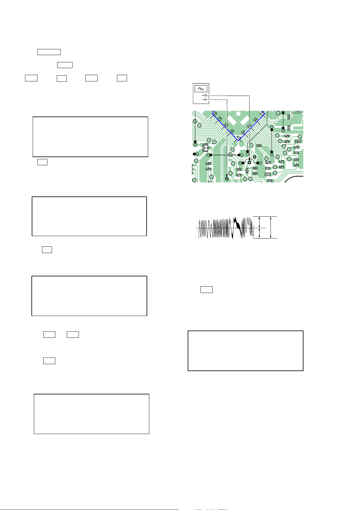
9. EF BALANCE ADJUSTMENT
Note 1: Data will be erased during MO reading if a recorded
disc is used in this adjustment.
Note 2: If the traverse waveform is not clear, connect the
oscilloscope as shown in the following figure so that
it can be seen more clearly.
oscilloscope
(DC range)
Connection:
oscilloscope
(DC range)
[MD BOARD]
L509
17
R518
C519
R538
TP505
C520
(RF)
C550
C522
37
40
C546
36
TP506
R5
(VC)
3035
IC502
R540
(SIDE B)
R532
R533
R535
R531
R525
C521
C526
R519
R524
TP504
(TE)
25
24
20
Adjusting Procedure:
1. Connect an oscilloscope to TP504 (TE) and TP506 (VC) on
the MD board.
2. Load a disc (any available on the market). (Refer to Note 1)
3. Press the M button to move the optical pick-up outside the
pit.
4. Turn the JOG dial to display “EFBAL ADJUST”.
5. Press the YES/ENTER button to display “EFB = MO-R”.
(Laser power READ power/Focus servo ON/tracking servo OFF/
spindle (S) servo ON)
6. Turn the JOG dial so that the waveform of the oscilloscope be
comes the specified value.
(When the JOG dial is turned, the of “EFB = ” changes
and the waveform changes ) In this adjust-ment, wave form var
ies at intervals of approx. 2 %. Adjust the waveform so that the
specified value is satisfied as much as possible.
(Read power traverse adjustment)
Traverse Waveform
Ω
MD BOARD
25
TP504
(TE)
24
20
(SIDE B)
R532
R535
R531
C521
R533
R525
C526
R524
R519
7. Press the YES/ENTER button and save the result of adjust-
8. Turn the JOG dial so that the waveform of the oscilloscope be
L509
17
R518
C519
R538
TP505
C520
(RF)
C550
C522
37
40
C546
36
TP506
R5
(VC)
3035
IC502
R540
VC
Specification : A = B
ment to the non-volatile memory. (“EFB = SAVE” will be
displayed for a moment. Then “EFB = MO-W” will be displayed)
comes the specified value.
(When the JOG dial is turned, the of “EFB- ” changes and
the waveform changes) In this adjustment, waveform varies at
intervals of approx. 2%. Adjust the waveform so that the specified value is satisfied as much as possible.
(Write power traverse adjustment)
Traverse Waveform
VC
Specification : A = B
23
ZS-M30
A
B
A
B
e
9. Press the YES/ENTER button, and save the adjustment re sults in the non-volatile memory. (“EFB = SAVE” will be
displayed for a moment)
10. “EFB =
MO-P” will be displayed.
The optical pick-up moves to the pit area automatically and
servo is imposed.
11. Turn the JOG dial until the waveform of the oscilloscope moves
closer to the specified value.
In this adjustment, waveform varies at intervals of approx. 2%.
Adjust the waveform so that the specified value is satisfied as
much as possible.
Traverse Waveform
VC
Specification : A = B
12. Press the YES/ENTER button, and save the adjustment re-
sults in the non-volatile memory. (“EFB =
SAVE” will be
displayed for a moment)
Next “EFBAL ADJUST” is displayed. The disc stops rotating
automatically.
13. Press the Z (MD) button and take out the disc.
14. Load the check disc (MD) TDYS-1.
15. Press the YES/ENTER button to display “EFB =
CD”.
Servo is imposed automatically.
16. Turn the JOG dial so that the waveform of the oscilloscope
moves closer to the specified value.
In this adjustment, waveform varies at intervals of approx.
2%.
Adjust the waveform so that the specified value is satisfied as
much as possible.
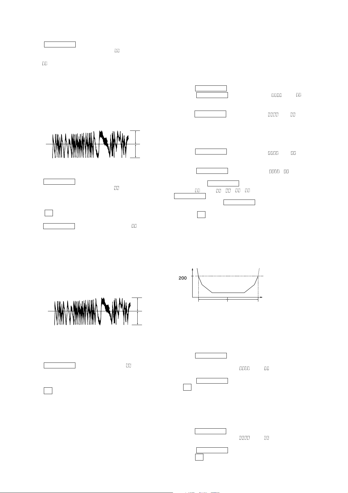
10. FOCUS BIAS ADJUSTMENT
Adjusting Procedure:
1. Load the continuously-recorded disc.
(Refer to “5. CREATING CONTINUOUSLY-RECORDED
DISC”)
2. Turn the JOG dial to display “CPLAY MODE”.
3. Press the YES/ENTER button to display “CPLAY MID”.
4. Press the NO/CANCEL button when “C1 = AD = ”
is displayed.
5. Turn the JOG dial to display “FBIAS ADJUST”.
6. Press the YES/ENTER button to display “ / a = ”.
The first four digits indicate the C1 error rate, the two digits
after “ / ” indicate ADER, and the 2 digits after “a =” indicate
the focus bias value.
7. Turn the JOG dial clockwise and find the focus bias value at
which the C1 error rate becomes about 200 (Refer to Note 2).
8. Press the YES/ENTER button to display “ / b = ”.
9. Turn the JOG dial counterclockwise and find the focus bias
value at which the C1 error rate becomes about 200.
10. Press the YES/ENTER button to display “ / c = ”.
11. Check that the C1 error rate is below 50 and ADER is 00.
Then press the YES/ENTER button.
12. If the “( )” in “ - - ( )” is above 20, press the
YES/ENTER button.
If below 20, press the NO/CANCEL button and repeat the
adjustment from step 2.
13. Press the Z (MD) button and take out the disc.
Note 1: The relation between the C1 error and focus bias is as shown in
the following figure. Find points A and B in the following figure
using the above adjustment. The focal point position C is automatically calculated form points A and B.
Note 2: As the C1 error rate changes, perform the adjustment using the
average value.
C1 error
about
Traverse Waveform
VC
Specification : A = B
17. Press the YES/ENTER button, display “EFB = SAVE” for
a moment and save the adjustment results in the non-volatile
memory.
Next “EFBAL ADJUST” will be displayed.
18. Press the Z (MD) button and take out the disc.
Focus bias valu
(F.BIAS)
B
C
A
11. ERROR RATE CHECK
11-1. CD Error Rate Check
Checking Procedure:
1. Load the check disc (MD) TDYS-1.
2. Turn the JOG dial and display “CPLAY MODE”.
3. Press the YES/ENTER button twice and display “CPLAY
MID”.
4. The display changes to “C1 = AD = ”.
5. Check that the C1 error rate is below 20.
6. Press the NO/CANCEL button to stop playback, then press
the Z (MD) button and take out the check disc.
11-2. MO Error Rate Check
Checking Procedure:
1. Load the continuously-recorded disc. (Refer to “5. CREATING
CONTINUOUSLY-RECORDED DISC”)
2. Turn the JOG dial to display “CPLAY MODE”.
3. Press the YES/ENTER button to display “CPLAY MID”.
4. The display changes to “C1 =
AD = ”.
5. If the C1 error rate is below 50, check that ADER is 00.
6. Press the NO/CANCEL button to stop playback, then
press the Z (MD) button and take out the test disc.
24
ZS-M30
2.
CD
test mode 2
Press the
x
(CD) button
Press the
x
(CD) button
3. STOP mode 2
4. FOCUS mode
5. ALL SERVO
ON mode
6.
LPC OFF
mode
7. TRACKING
GAIN UP mode
8.
High speed
mode
Press the
u
(CD) button
Press the
u
(CD) button
Press the x (CD)
button.
Press the u ,(CD)
button.
Press the x (CD)
button.
Press the x (CD)
button.
Press the x (CD)
button.
Press the x (CD)
button.
Press the u ,(CD)
button.
Press the u ,(CD)
button.
Press the u ,(CD)
button.
Press the u ,(CD)
button.
Press the u ,(CD)
button.
1.
CD
test mode 1
Enter the
CD test mode
CD test mode
12. FOCUS BIAS CHECK
Change the focus bias and check the focus tolerance amount.
Checking Procedure:
1. Load the continuously-recorded disc. (Refer to “5. CREATING
CONTINUOUSLY-RECORDED DISC”)
2. Turn the JOG dial to display “CPLAY MODE”.
3. Press the YES/ENTER button twice to display “CPLAY
MID”.
4. Press the NO/CANCEL button when “C1 = AD = ”
is displayed.
5. Turn the JOG dial to display “FBIAS CHECK”.
6. Press the YES/ENTER button to display “ / c = ”.
The first four digits indicate the C1 error rate, the two digits
after “ / ” indicate ADER, and the 2 digits after “c =” indicate
the focus bias value.
Check that the C1 error is below 50 and ADER is below 2.
7. Press the YES/ENTER button and display “ / b = ”.
Check that the C1 error is about 200 and ADER is below 2.
8. Press the YES/ENTER button and display “ / a = ”.
Check that the C1 error is about 200 and ADER is below 2.
9. Press the NO/CANCEL button, then press the Z (MD)
button and take out the disc.
Note 1: If the C1 error and ADER are above other than the speci-
fied value at points A (step 8. in the above) or B (step 7. in
the above), the focus bias adjustment may not have been
carried out properly. Adjust perform the beginning again.
5-3. CD SECTION
Set the CD test mode when performing confirmations.
After completing the confirmation, release the CD test mode.
In the CD test mode, the set works as following sequence.
CD test mode sequence:
25
ZS-M30
(VC)
1. Entering the CD test Mode
1. Press POWER button to turn on the power.
2. Place CD into tray (TOC data of the CD will be read).
3. Press and hold EDIT button, then press CD buttons in the
following order:
u (CD)t x (CD)t u (CD)t x (CD)
4. All LED and LCD segments start flashing.
5. Press any button to stop flashing of LED and LCD segments and
to shoe the following display.
Display
88
PGM
6. Press x (CD)button to enter CD test mode (STOP MODE 1)
and to show the following display.
Display
81
PGM
2. STOP Mode 2
1. Press the x (CD) button to enter the STOP mode 2, and dis-
play as below.
Display
2. Connect an oscilloscope to TP (TE) and TP (VC) on the CD
board.
Connection:
oscilloscope
(DC range)
TP (VC)
10
JW715
Q701
TP (TE)
21
Q702
R783
R786
JW724
TP
IC702
C716
R713
41
JW720
TP(TE)
C715
R715
C714
C720
(RF)
TP
[CD BOARD]
0
JW7
JW701
R716
C721
C722
R717
R718
JW719
R722
R721
(SIDE B)
J
C731
C730
C726
C723
R719
C
R7
3. Confirm that the traverse level of waveform satisfy specified
value as follows.
Traverse Waveform
A
VC
traverse level:
0.65 to 1.20 Vp-
B
A = B
Specified Value:
traverse level: 0.65 to 1.20 Vp-p
82
PGM
2. Press the M and m button to move the optical pick-up to
position of the track where signal is recorded.
3. FOCUS Mode (Traverse Confirmation)
1. Press the u (CD ) button to enter the FOCUS mode and dis
play as below. (Focus servo ON. CLV-S, tacking and sled servo
OFF)
Display
F-
PGM
4. ALL SERVO ON Mode 1
(RF Level and Jitter Confirmation 1)
1. Press the u (CD) button four times to enter the ALL SERVO
ON
mode 1 (start playback the disc) and display as below.
(All servo ON. LPC ON)
Display
P-
PGM
26
 Loading...