

Sony YS-W270, YS-W270P Operating Instructions Manual
Camera Adaptor
3-205-448-14 (1)
Operating Instructions
Mode d’emploi
Bedienungsanleitung
Manual de instrucciones
Istruzioni per l’uso
使用说明书
GB
FR
DE
ES
IT
CS
YS-W270/W270P
2000 Sony Corporation
1 (CS)
English
Important Safety Instructions
• Read these instructions.
• Keep these instructions.
• Heed all warnings.
• Follow all instructions.
• Do not use this apparatus near water.
• Clean only with dry cloth.
• Do not block any ventilation openings. Install in accordance
with the manufacturer’s instructions.
• Do not install near any heat sources such as radiators, heat
registers, stoves, or other apparatus (including amplifiers)
that produce heat.
• Do not defeat the safety purpose of the polarized or
grounding-type plug. A polarized plug has two blades with
one wider than the other. A grounding-type plug has two
blades and a third grounding prong. The wide blade or the
third prong are provided for your safety. If the provided plug
does not fit into your outlet, consult an electrician for
replacement of the obsolete outlet.
• Protect the power cord from being walked on or pinched
particularly at plugs, convenience receptacles, and the
point where they exit from the apparatus.
• Only use attachments/accessories specified by the
manufacturer.
• Use only with the cart, stand, tripod, bracket,
or table specified by the manufacturer, or sold
with the apparatus. When a cart is used, use
caution when moving the cart/apparatus
combination to avoid injury from tip-over.
• Unplug this apparatus during lightning storms or when
unused for long periods of time.
• Refer all servicing to qualified service personnel. Servicing
is required when the apparatus has been damaged in any
way, such as power-supply cord or plug is damaged, liquid
has been spilled or objects have fallen into the apparatus,
the apparatus has been exposed to rain or moisture, does
not operate normally, or has been dropped.
Owner’s Record
The model and serial numbers are located on the bottom.
Record the model number and serial number in the space
provided below. Refer to them whenever you call upon your
Sony dealer regarding this product.
Model No. ______________ Serial No. ______________
WARNING
To prevent fire or shock hazard, do not expose the
unit to rain or moisture.
To avoid electrical shock, do not open the cabinet.
Refer servicing to qualified personnel only.
THIS APPARATUS MUST BE EARTHED
This symbol is intended to alert the user to
the presence of uninsulated “dangerous
voltage” within the product’s enclosure that
may be of sufficient magnitude to constitute
a risk of electric shock to persons.
2 (GB)
This symbol is intended to alert the user to
the presence of important operating and
maintenance (servicing) instructions in the
literature accompanying the appliance.

For customers in the USA (YS-W270 only)
This equipment has been tested and found to comply with
the limits for a Class B digital device, pursuant to Part 15 of
the FCC Rules. These limits are designed to provide
reasonable protection against harmful interference in a
residential installation. This equipment generates, uses and
can radiate radio frequency energy and, if not installed and
used in accordance with the instructions, may cause harmful
interference to radio communications. However, there is no
guarantee that interference will not occur in a particular
installation. If this equipment does cause harmful
interference to radio or television reception, which can be
determined by turning the equipment off and on, the user is
encouraged to try to correct the interference by one or more
of the following measures:
• Reorient or relocate the receiving antenna.
• Increase the separation between the equipment and
receiver.
• Connect the equipment into an outlet on a circuit different
from that to which the receiver is connected.
• Consult the dealer or an experienced radio/TV technician
for help.
You are cautioned that any changes or modifications not
expressly approved in this manual could void your authority
to operate this equipment.
GB
English
The shielded interface cable recommended in this manual
must be used with this equipment in order to comply with the
limits for a digital device pursuant to Subpart B of Part 15 of
FCC Rules.
CAUTION
The apparatus shall not be exposed to dripping or splashing
and no objects filled with liquid, such as vases, shall be
placed on the apparatus.
The disconnect device of this equipment is the power switch
located on the front. Function of the switch is as follows:
ON(symbol ?): Mains power is supplied.
OFF(symbol a): Mains power is disconnected.
Caution: The power switch shall remain readily operable.
3 (GB)


Table of Contents
Features..................................................................... 6 (GB)
Precautions ............................................................... 6 (GB)
Location and Function of Parts and Controls ....... 8 (GB)
Connections ............................................................ 10 (GB)
Notes on Connections ............................................ 10 (GB)
Using One YS-W270/W270P ................................ 10 (GB)
Connecting more than one camera adaptor............ 11 (GB)
Combining a multiplexer ....................................... 13 (GB)
Specifications ......................................................... 14 (GB)
5 (GB)

Features
The YS-W270/W270P camera adaptor can be connected to a Sony SSCseries camera or the SPT-M320/M320CE video camera (multiplex
transmission capability), providing it with power and an external
synchronization signal while also transmitting the video signals from the
camera to a monitor.
The adaptor has 4 camera input connectors and 8 video output connectors,
allowing for connection of up to 4 cameras and 8 monitors.
If you are using an SSC series camera, see “Notes on Connections” on page 10
(GB).
•Only a single 75-ohm coaxial cable is needed to send synchronization
signals, video signals and power.
• If you connect multiple cameras that have different synchronization
methods (VS or VD), they can be synchronized.
• The SYNC MODE switch allows you to switch the synchronization mode
according to the source signal.
– In the PRIMARY mode you can output synchronization signals from
the YS-W270/W270P.
– In the SECONDARY mode you can connect more than one YS-W170/
W170P or YS-W270/W270P using external synchronization signals.
There is no image disturbance when you switch the camera. (For details
on connection, see the Connection section.)
• The YS-W270/W270P has a built-in cable compensation circuit that
allows you to switch the video signal compensation level according to the
cable length.
• The YS-W270/W270P can be used with both VS and VD cameras, which
means the adaptor is compatible with all camera models in any series. If
you connect the adaptor to a VD camera, you don’t need to adjust the HPhase at the time of installation.
•You can output the video signals to two systems.
Precautions
Power supply
Foreign objects
6 (GB)
Be sure to operate the camera adaptor according to the power requirements
outlined under “Specifications” on page 14 (GB).
Be careful not to spill liquids, or drop any flammable or metal objects into
the body of the unit.

Operating and storage locations
Avoid operating or storing the unit in the following locations.
• Extremely hot or cold places (operating temperature:
• In direct sunlight for long periods, or close to heating equipment
•Damp or dusty places
•Where it is exposed to rain
• Locations subject to strong vibration
•Near strong magnetic fields
•Close to generators producing powerful electromagnetic radiation, such
Care
•Clean the cabinet with a soft, dry cloth. If it is very dirty, use a cloth
•Avoid the use of volatile solvents such as alcohol, benzene, and thinners.
Ventilation
–10 °C to +50 °C [14 °F to 122 °F])
as radio or TV transmitters
dampened with a small quantity of neutral detergent, then wipe dry.
They may damage the surface finish, or impair the operation of the unit.
Miscellaneous
Rack mounting
Do not wrap the unit in a cloth, etc., during operation. This may cause the
internal temperature to rise excessively and the camera adaptor to
malfunction.
•Be careful not to spill water or other liquids on the unit or allow
combustible or metallic objects inside the body. If used with foreign
objects inside, the unit is liable to fail or cause a fire or an electric shock.
• If the product is transported or shipped, repack it as originally packed at
the factory, or in materials equal in quality.
The unit can be mounted in an EIA standard 19-inch rack by attaching the
rack mounting brackets and screws (supplied).
In the event of any problems with the operation of the camera adaptor,
contact your authorized Sony dealer.
7 (GB)
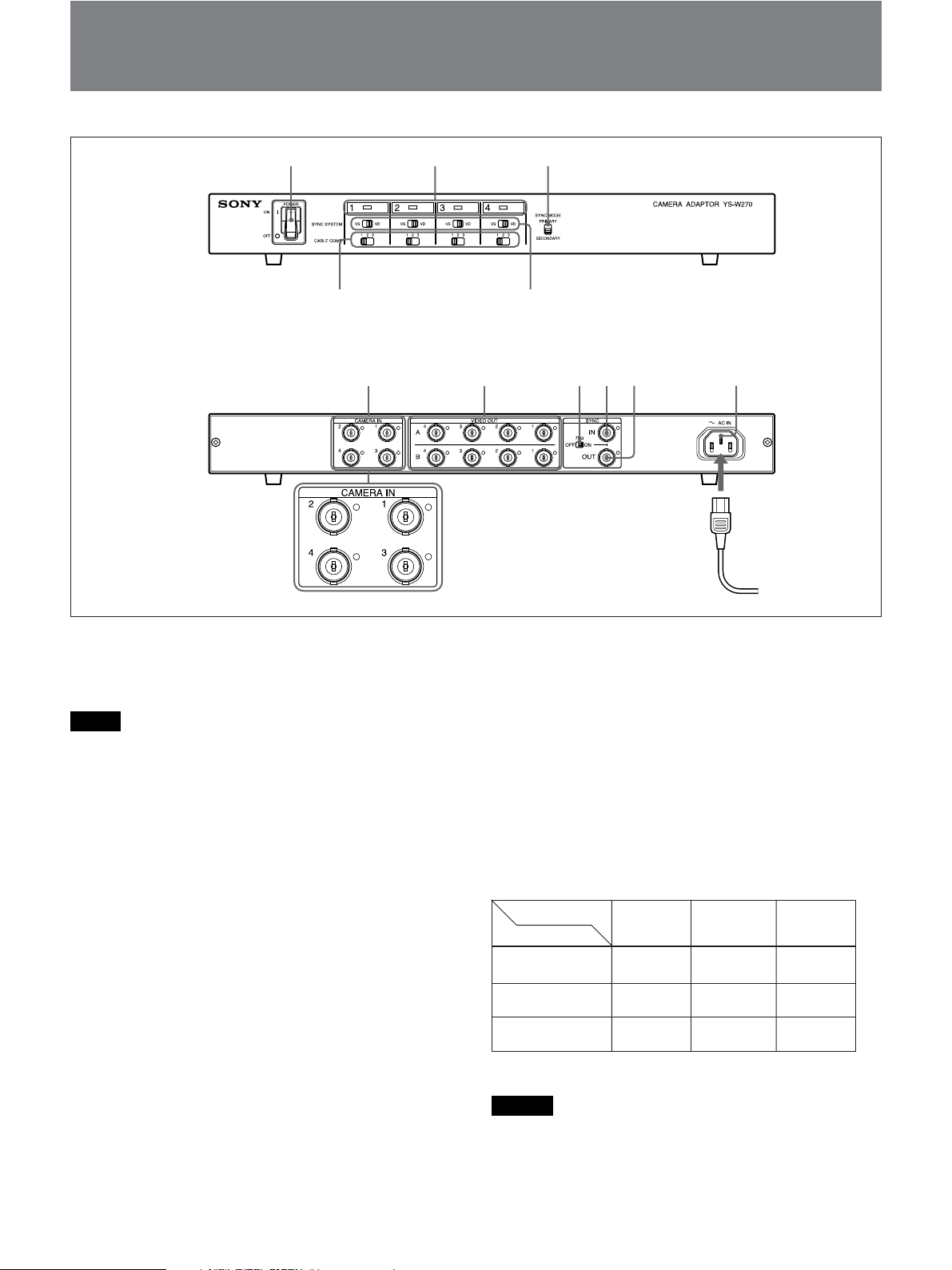
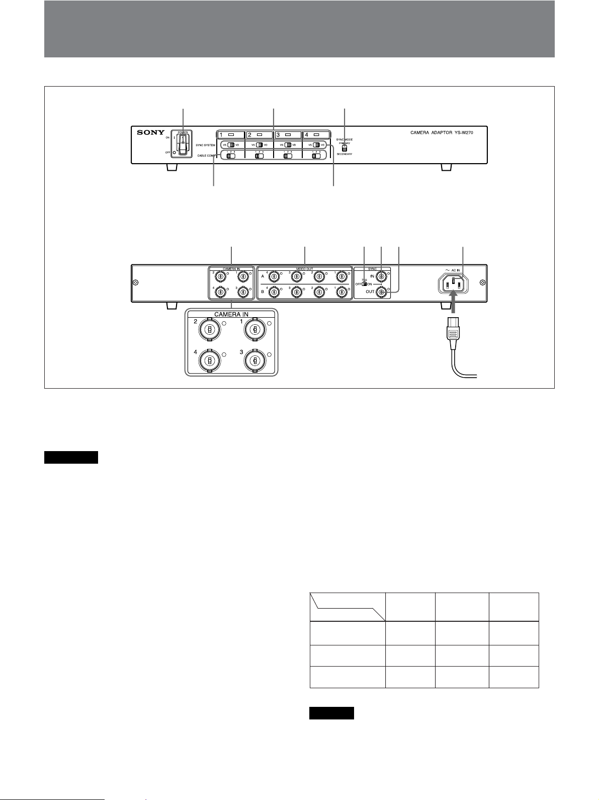
Location and Function of Parts and Controls
123
Front
54
67890qa
Rear
1 POWER switch
Switches the power to the unit and the connected
cameras on and off.
Notes
• If you connect a camera to this unit after switching
the power on, the camera will not operate. Be sure to
complete connections before switching the power on.
• If you switch the power off and want to switch it back
on, wait 10 seconds or more before doing so.
2 LED indicators (1 ~ 4)
Indicate which cameras are connected.
3 SYNC MODE switch
You can select the mode according to the
synchronization signal source.
You can switch the synchronization mode according to
the synchronization signals.
PRIMARY: Uses the synchronization signals from
the YS-W270/W270P.
SECONDARY: Uses external synchronization
signals when you connect multiple camera
adaptors, or uses the internal synchronization
signals from the camera.
4 SYNC SYSTEM switches (1 ~ 4)
You can select the mode according to the camera’s
synchronization method.
VS: Uses a VS method camera (conventional Video
Sync method).
VD: Uses a VD method camera.
5 CABLE COMP (1/2/3) switches (1 ~ 4)
Compensate for signal loss in the cable connection to
the camera. Set the switch depending on the cable type
and length according to the following table.
When using SSC-series cameras
Switch setting
Cable type
RG-59B/U (3C-2V)
RG-6A/U (5C-2V)
RG-11A/U (7C-2V)
Caution
1
max. 100 m
(328 ft.)
max. 160 m
(524 ft.)
max. 200 m
(656 ft.)
2
max. 200 m
(656 ft.)
max. 330 m
(1082 ft.)
max. 400 m
(1312 ft.)
3
max. 300 m
(984 ft.)
max. 500 m
(1640 ft.)
max. 600 m
(1968 ft.)
The resistance of the cable should be 30 ohms or less.
8 (GB)

6 CAMERA IN connectors (1 ~ 4) (BNC-type)
Connect to the DC IN.VS IN/VIDEO OUT connector
of any SSC-series camera or the SPT-M320/M320CE
video camera with multiplex transmission capability.
Note
When using a SSC-series camera or the SPT-M320/
M320CE video camera, be careful not to connect the
CAMERA IN connector on the camera adaptor with
the MONITOR OUT connector on the camera; doing
so may lead to damage or breakdown of the camera.
Always be sure to connect to the VIDEO OUT
connector on the camera.
If you are using an SSC series camera, see “Notes on
Connections” on page 10 (GB).
0 SYNC OUT connector (BNC-type)
The signals output from the SYNC OUT connector
differ depending on the mode (PRIMARY/
SECONDARY) selected by the SYNC MODE switch
3.
PRIMARY: Outputs the synchronization signals
from the YS-W270/W270P (compatible with the
SYNC SYSTEM switch in CAMERA IN 1 (VD/
VS)).
SECONDARY: Outputs the synchronization signals
input to the SYNC IN connector.
Note
The external synchronization signals are not output
unless the camera adaptor is turned on.
7 VIDEO OUT A and B connectors (1 ~ 4)
(BNC-type)
Connect to the video input connector of a video
monitor to output the video signals input from the
CAMERA IN connectors (1 ~ 4). The A and B
connectors output the same signals.
8 75Ω (ON/OFF) switch
Controls the 75-ohm termination of the SYNC IN
connector.
•When using the SYNC IN connector only, set this
switch to ON.
•When using the SYNC IN and SYNC OUT
connectors, set this switch to OFF.
Note
If you are using neither the SYNC IN nor SYNC OUT
connector, set the switch to ON.
9 SYNC IN connector (BNC-type)
You can input external synchronization signals.
Notes
• Set the SYNC MODE switch 3 to SECONDARY to
synchronize the camera. (See “Connecting more than
one camera adaptor” on page 11 (GB) in the
Connection section.)
• If you connect multiple cameras that have different
synchronization methods, input the VS (or VBS)
synchronization signals.
qa AC IN connector
Connects to a 100 – 120 V AC outlet (YS-W270) or a
220 – 240 V AC outlet (YS-W270P).
9 (GB)
Connections
Notes on Connections
• This unit will only operate when connected to a Sony
SSC-series camera or the SPT-M320/M320CE video
camera with multiplex transmission capability. When
making the connections, refer also to the operation
manual for the connected video camera module.
If you connect the unit to an older model of the SSC series,
please contact your Sony dealer.
• Turn off the power to all the equipment while making
the system connections. If you connect a camera to
this unit after switching the power on, the camera will
not be supplied with power.
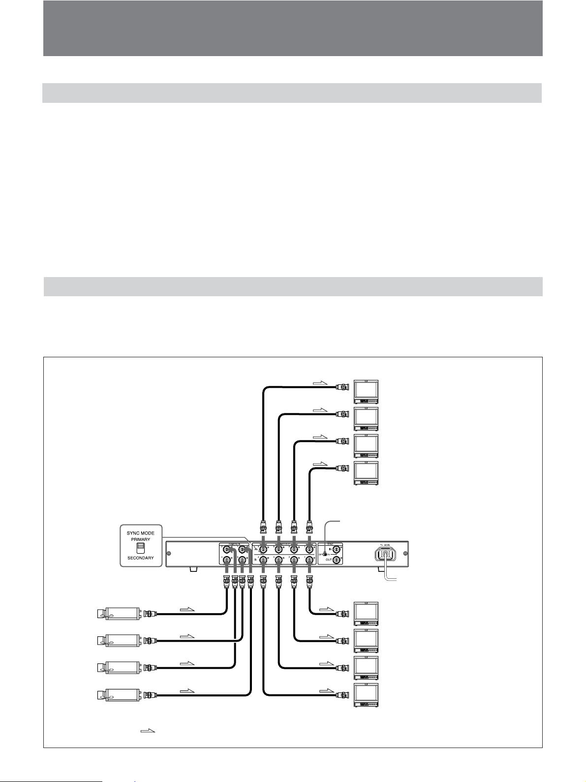
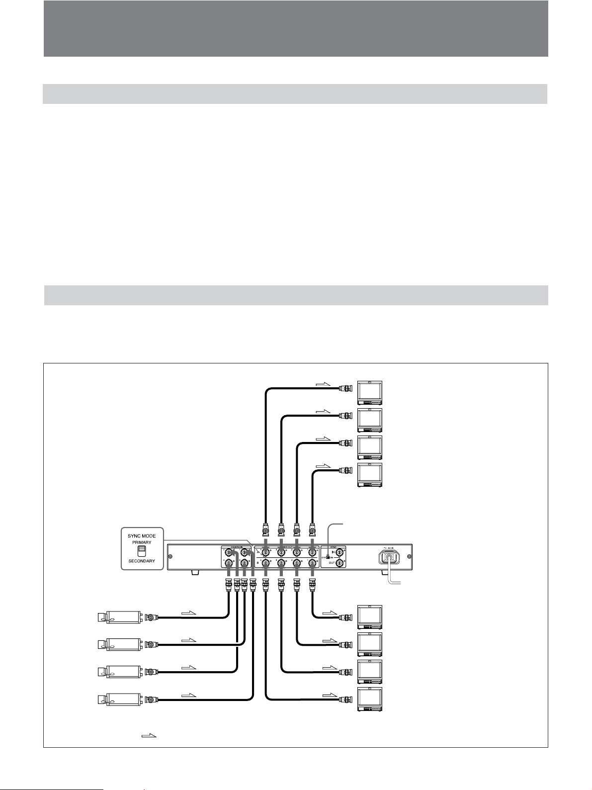
Using One YS-W270/W270P
Using one YS-W270/W270P you can set up a system
of up to four cameras, with two monitors for each
camera.
to video input
connector
• The cables connecting this unit to the video cameras
carry the power supply and synchronization signal in
addition to the camera video output signal. It is
therefore not possible to add a booster or other device
between the unit and a camera.
•Always use a 75-ohm coaxial cable of the length
specified in the tables on page 8 (GB) when connecting
a video camera to this unit; use of an incorrect cable can
lead to camera malfunction. Also be sure to set the cable
compensation switch correctly.
Make all the connections before setting the POWER
switch of this unit to ON.
Video monitor
Picture from camera 4
Picture from camera 3
Picture from camera 2
to VIDEO
OUT A 1
to 4
[SYNC MODE:
PRIMARY]
(Front)
Camera
4
3
2
1
to CAMERA
IN 1 to 4
to DC IN. VS IN/
VIDEO OUT
to video input
connector
75Ω
to VIDEO
OUT B 1
to 4
75Ω: ON
YS-W270/W270P
Video monitor
Picture from camera 1
to an AC outlet
Picture from camera 1
Picture from camera 2
Picture from camera 3
Picture from camera 4
10 (GB)
Video signal flow
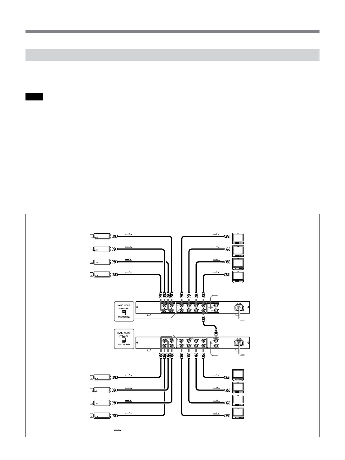
Connecting more than one camera adaptor
Using the synchronization signals from the YS-W270/
W270P or external unit allows you to synchronize the
cameras connected to second or more camera adaptors.
Notes
• If you connect multiple cameras that have different
synchronization methods, connect the VD camera to the
CAMERA IN 1 connector on the first camera adaptor,
and connect the VIDEO OUT on the first camera
adaptor to the SYNC IN on the second camera adaptor.
• If you use the line lock camera for the external
synchronization signal source, you may not be able to
synchronize the cameras.
• If a number of YS series camera adaptors (except YSW270/W270P/W170/W170P) are used together, it
may be difficult to provide synchronization, depending
please keep the following points in mind.
– Be sure to connect a YS-W270/W270P as the first
unit in the configuration, connecting the other YS
series camera adaptors in sequence, starting from the
second one. If there are more YS-W270/W270P
camera adaptors in addition to the first one, connect
all of the remaining YS-W270/W270P camera
adaptors together at the end of the sequence.
– At this time, set the 75Ω switch of the second unit
only to ON. Set the 75Ω switches of all of the other
units to OFF.
– If you have a VD synchronization camera such as
the SSC-DC310P, be sure to connect the YS-W270/
W270P first in the sequence, then connect the VD
camera’s output (VIDEO OUT B) to the SYNC IN
of the second unit.
on how they are connected. In a case such as this,
For more details on connection methods, see page 13 (GB).
Connecting two camera adaptors 1: Synchronizing the cameras by the synchronization signals from the YS-W270/
W270P
1
Camera
to DC IN. VS IN/
VIDEO OUT
to video input
connector
Video monitor
Picture from camera 4
2
3
4
[SYNC MODE:
PRIMARY]
(Front)
[SYNC MODE:
SECONDARY]
(Front)
Camera
5
6
7
8
to CAMERA
IN 1 to 4
to CAMERA
IN 1 to 4
to DC IN.VS IN/VIDEO OUT
Video signal flow
B
to VIDEO
OUT B1
to video input
connector
to VIDEO
OUT 1 to 4
75Ω: ON
to SYNC IN
75Ω: ON
to VIDEO
OUT 1 to 4
Picture from camera 3
Picture from camera 2
Picture from camera 1
YS-W270/W270P
to an AC outlet
YS-W270/W270P
to an AC outlet
Picture from camera 5
Picture from camera 6
Picture from camera 7
Picture from camera 8
Video monitor
11 (GB)
Connections
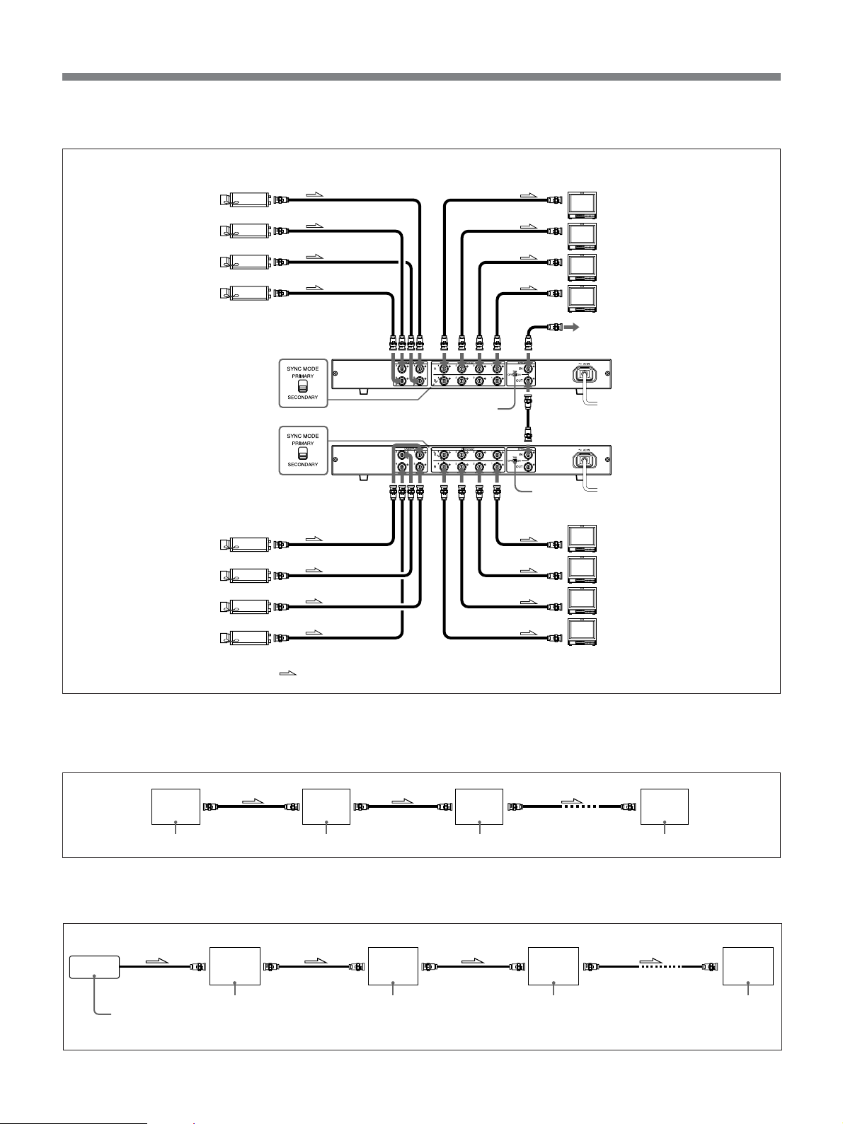
Connecting two camera adaptors 2: Synchronizing the cameras by external synchronization signals
Camera
1
2
3
4
[SYNC MODE:
SECONDARY]
(Front)
[SYNC MODE:
SECONDARY]
(Front)
Camera
5
6
7
8
to DC IN. VS IN/
VIDEO OUT
to CAMERA
IN 1 to 4
to CAMERA
IN 1 to 4
to DC IN. VS IN/VIDEO OUT
Video signal flow
to video input
connector
75Ω: OFF
to video input
connector
to VIDEO
OUT 1 to 4
to SYNC IN
to SYNC OUT
to SYNC IN
75Ω: ON
to VIDEO
OUT 1 to 4
Video monitor
Picture from camera 4
Picture from camera 3
Picture from camera 2
Picture from camera 1
External sync signal source
YS-W270/W270P
to an AC outlet
YS-W270/W270P
to an AC outlet
Picture from camera 5
Picture from camera 6
Picture from camera 7
Picture from camera 8
Video monitor
Connecting the synchronization signals and switch settings for 3 or more cameras - Example 1:
Synchronizing the cameras with the synchronization signal from the YS-W270/W270P
First
YS-W270/
W270P
75Ω switch: ON
to VIDEO OUT
Second
YS-W270/
W270P
75Ω switch: OFF
to SYNC OUT to SYNC OUT
to SYNC IN
Third
YS-W270/
W270P
75Ω switch: OFF 75Ω switch: ON
Last
YS-W270/
to SYNC INto SYNC IN
W270P
Connecting the synchronization signals and switch settings for 3 or more cameras - Example 2:
Synchronizing the cameras with the external synchronization signal
to SYNC IN
External
synchronization
signal source
to SYNC OUT
First
YS-W270/
W270P
to SYNC IN
Second
YS-W270/
W270P
75Ω switch: OFF 75Ω switch: OFF
to SYNC OUT
to SYNC IN
Third
YS-W270/
W270P
75Ω switch: OFF 75Ω switch: ON
to SYNC OUT
to SYNC IN
12 (GB)
Last
YS-W270/
W270P
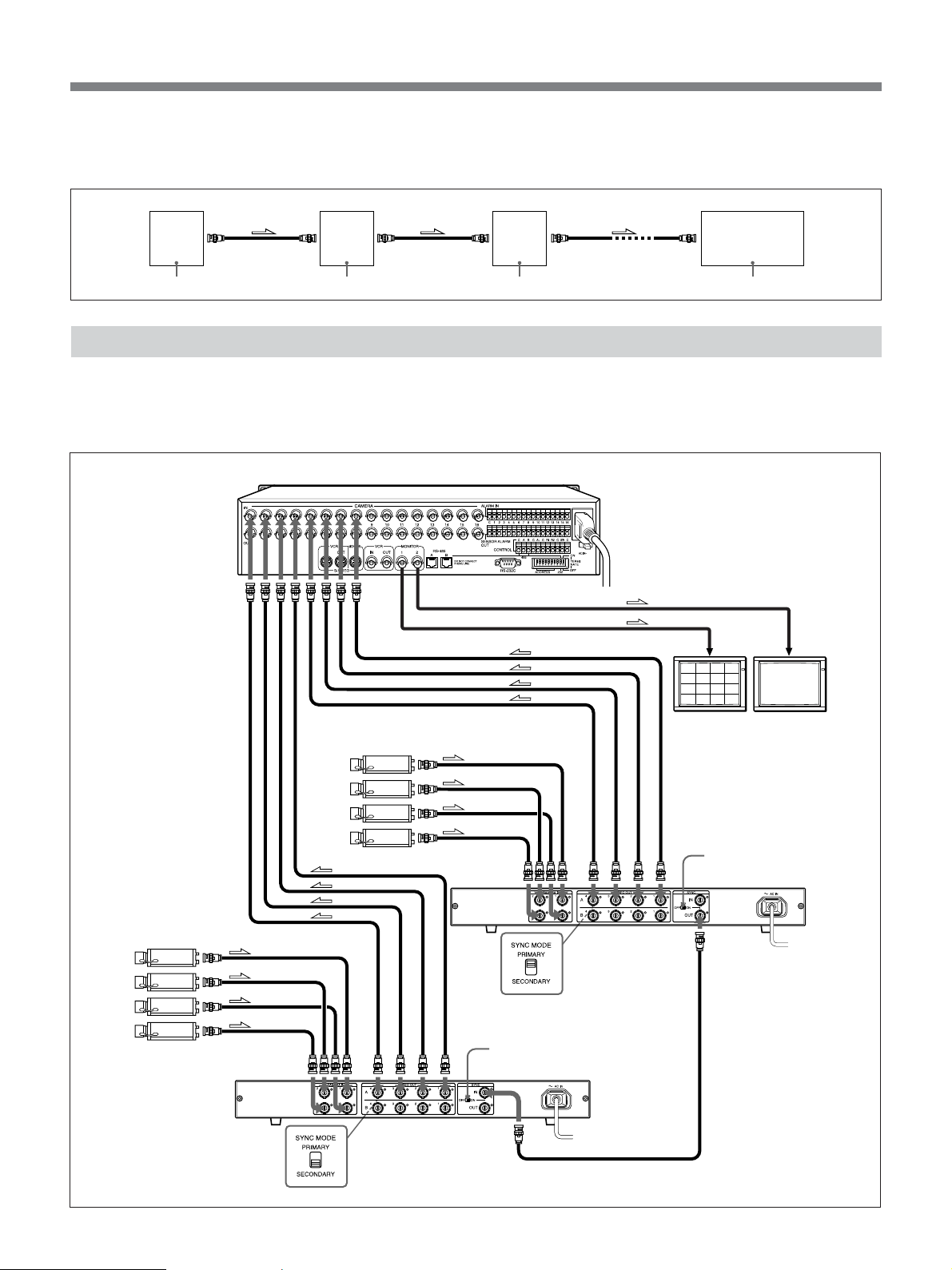
Connecting the synchronization signals and switch settings for 3 or more cameras - Example 3:
Synchronizing the cameras with the synchronization signals from a number of YS series camera adaptors
First
YS-W270/
W270P
75Ω switch : OFF
to VIDEO OUT B
connector
to SYNC IN
connector
Second
Another
YS series
adaptor
75Ω switch : ON
to SYNC OUT
connector
Combining a multiplexer
If you use a Sony multiplexer YS-DX516/DX516P
you can display images from multiple cameras; for
example, simultaneously in a split screen on one
to camera input
connector
Third
Another
YS series
to SYNC IN
connector
adaptor
75Ω switch : OFF 75Ω switch : OFF
monitor, or sequentially automatically switching the
images one by one.
YS-DX516/DX516P
to MONITOR 1,2
to SYNC OUT
connector
to SYNC IN
connector
to an AC outlet
to video input connector
Last
YS-W270/W270P or
another YS series
adaptor
Camera
5
6
7
8
l Video signal flow
1
2
3
4
to DC IN.VS IN/VIDEO OUT
to CAMERA
IN 1 to 4
Camera
to DC IN. VS IN/VIDEO OUT
[SYNC MODE:
SECONDARY]
(Front)
to CAMERA
IN 1 to 4
to VIDEO
OUT 1 to 4
75Ω: ON
YS-W270/W270P
to SYNC IN
[SYNC MODE:
PRIMARY]
(Front)
to an AC outlet
Video monitor
to VIDEO OUT
1 to 4
75Ω: ON
YS-W270/W270P
to an AC outlet
to SYNC
OUT
13 (GB)

Specifications
Power supply YS-W270 : 100 to 120 V AC,
50/60 Hz
YS-W270P : 220 to 240 V AC,
50/60 Hz
Power consumption 49.5 W
Input connectors CAMERA IN 1 to 4 (BNC) × 4
SYNC IN (BNC) × 1
Composite sync signal: 4 Vp-p,
75 ohms terminated
VS (video/sync): 1 Vp-p,
75 ohms terminated
VBS (video/burst/sync): 1 Vp-p,
75 ohms terminated
VD (sync): 1 Vp-p, 75 ohms
terminated
Output connectors VIDEO OUT 1 to 4 A, B (BNC)
×
8
Composite video signal: 1 Vp-p,
75 ohms terminated
SYNC OUT (BNC) × 1
PRIMARY: VD/VS signals
output from YS-W270/
W270P, synchronized by the
SYNC SYSTEM switch in
CAMERA IN 1 (VS/VD)
SECONDARY: Through
output of signals input to the
SYNC IN connector
Operating temperature
–10 °C to +50 °C
(14 °F to 122 °F)
Dimensions (w/h/d) 424 × 52 × 345 mm
Mass Approx. 3.6 kg (7 lb 15 oz)
Accessories supplied Operating Instructions (1)
3
(16
/4 × 2 1/8 × 13 5/8 inches)
AC power cord (1)
Rack mounting brackets and
screws (EIA standard) (1 set)
Design and specifications are subject to change
without notice.
14 (GB)


Français
AVERTISSEMENT
Pour prévenir tout risque d’incendie ou
d’électrocution, garder cet appareil à l’abri
de la pluie et de l’humidité.
Pour prévenir tout risque d’électrocution,
ne pas ouvrir le boîtier. Confier l’entretien
de cet appareil exclusivement à un
personnel qualifié.
CET APPAREIL DOIT ÈTRE RELIÉ À LA
TERRE.
ATTENTION
Eviter d’exposer l’appareil à un égouttement ou à des
éclaboussures et ne placer aucun objet rempli de
liquide, comme un vase, sur l’appareil.
Le dispositif de mise hors tension de cet appareil est
l’interrupteur situé à l’avant. Le fonctionnement de
l’interrupteur est le suivant :
ON (symbole ?): l’appareil est alimenté.
OFF (symbole a): l’alimentation secteur est coupée.
Attention : l’interrupteur doit rester accessible en
permanence.
2 (FR)

Table des matières
Caractéristiques ........................................................ 4 (FR)
Précautions ................................................................ 4 (FR)
Emplacement et fonction des composants et des
commandes ........................................................... 6 (FR)
Raccordement............................................................ 8 (FR)
Remarques sur le raccordement ................................ 8 (FR)
Utilisation d’un adaptateur YS-W270/W270P ......... 8 (FR)
Raccordement de plusieurs adaptateurs de caméra... 9 (FR)
Association d’un multiplexeur ................................ 11 (FR)
Spécifications .......................................................... 12 (FR)
FR
Français
3 (FR)

Caractéristiques
L’adaptateur de caméra YS-W270/W270P peut être connecté à une caméra
Sony de la série SSC ou à la caméra vidéo SPT-M320/M320CE (à
transmission multiplex) en lui fournissant l’alimentation et un signal de
synchronisation externe tout en transmettant les signaux vidéo de la
caméra à un moniteur.
L’adaptateur est doté de quatre connecteurs d’entrée pour caméra et de huit
connecteurs de sortie vidéo, ce qui vous permet de raccorder 4 caméras et
8 moniteurs.
Si vous utilisez une caméra de la série SSC, reportez-vous aux “Remarques sur le
raccordement” à la page 8 (FR).
•Un seul câble coaxial de 75 ohms est nécessaire pour envoyer les signaux
de synchronisation, les signaux vidéo et l’alimentation.
• Si vous raccordez plusieurs caméras utilisant des méthodes de
synchronisation différentes (VS ou VD), il est possible de les
synchroniser.
• Le commutateur SYNC MODE vous permet de commuter le mode
synchronisation en fonction du signal source.
– En mode PRIMARY vous pouvez extraire les signaux de
synchronisation de l’adaptateur YS-W270/W270P.
– En mode SECONDARY vous pouvez raccorder plusieurs adaptateurs
YS-W170/W170P ou YS-W270/W270P à l’aide de signaux de
synchronisation externes. L’image n’est pas perturbée lorsque vous
mettez la caméra sous tension. (Pour plus de détails sur le
raccordement, reportez-vous à la section Raccordement.)
• L’adaptateur YS-W270/W270P est doté d’un circuit de compensation de
câble intégré qui vous permet de commuter le niveau de compensation du
signal vidéo suivant la longueur du câble.
• L’adaptateur YS-W270/W270P peut être utilisé avec des caméras VS et
VD, ce qui le rend compatible avec tous les modèles de caméras, quelle
que soit la série. Si vous raccordez l’appareil à une caméra VD, vous
n’avez pas besoin de régler la Phase-H lors de l’installation.
•Vous pouvez extraire les signaux vidéo vers deux systèmes.
Précautions
Alimentation
Corps étrangers
4 (FR)
Faites fonctionner l’adaptateur de caméra suivant la puissance de
raccordement définie dans la section “Spécifications” à la page 12 (FR).
Veillez à ne pas renverser de liquides ni à laisser tomber d’objets
inflammables ou métalliques dans le châssis de l’appareil.

Lieux de fonctionnement et d’entreposage
Evitez de faire fonctionner ou de ranger l’appareil dans des endroits :
• soumis à des températures extrêmement élevées ou basses (températures
d’utilisation : –10 °C à +50 °C [14 °F à 122 °F]);
• soumis au rayonnement direct du soleil pendant de longues périodes ou à
proximité d’installations de chauffage;
• soumis à de l’humidité et à de la poussière;
• soumis à la pluie;
• soumis à de fortes vibrations;
•à proximité de générateurs de puissants champs magnétiques;
•à proximité de générateurs produisant de puissantes radiations
électromagnétiques comme des transmetteurs de radio ou de télévision.
Entretien
•Nettoyez le châssis à l’aide d’un chiffon doux et sec. S’il est fortement
souillé, utilisez un chiffon légèrement imprégné d’un détergent neutre et
séchez-le ensuite.
• Evitez d’utiliser des solvants volatiles tels que de l’alcool, du benzène et
des diluants qui risqueraient de ternir le fini de l’appareil ou
d’occasionner un dysfonctionnement.
Ventilation
Divers
Montage sur une étagère
N’enveloppez pas l’appareil dans un chiffon, etc., lorsque vous l’utilisez.
Cela risquerait en effet de provoquer une surchauffe interne excessive et,
partant, un dysfonctionnement de l’adaptateur de caméra.
•Veillez à ne pas renverser d’eau ou d’autres liquides sur l’appareil et à ce
que des objets combustibles ou métalliques ne pénètrent à l’intérieur du
châssis. Si vous utilisez l’adaptateur de caméra alors que des corps
étrangers se sont introduits à l’intérieur, vous risquez d’occasionner un
dysfonctionnement ou encore de provoquer un incendie ou une décharge
électrique.
• Si le produit doit être transporté ou expédié, remballez-le dans son
conditionnement d’origine ou dans des matériaux de qualité comparable.
Cet appareil peut être monté sur une étagère de 19 pouces de normes EIA à
l’aide des supports et des vis de montage pour étagère (fournis).
Si vous rencontrez des problèmes lors de l’utilisation de cet adaptateur de
caméra, consultez votre centre de service après-vente Sony.
5 (FR)
Emplacement et fonction des composants et des
commandes
123
Avant
54
67890qa
Arrière
1 Interrupteur d’alimentation (POWER)
Met l’appareil ainsi que les caméras raccordées sous et
hors tension.
Remarques
• Si vous raccordez une caméra à cet appareil après
l’avoir mis sous tension, la caméra sera inopérante.
Veillez à terminer les raccordements avant de mettre
l’appareil sous tension.
• Si vous mettez l’appareil hors tension et que vous
souhaitez ensuite le remettre sous tension, attendez au
moins 10 secondes avant de le faire.
2 Inidcateurs LED (1 ~ 4)
Indique quelles caméras sont raccordées.
3 Commutateur SYNC MODE
Vous pouvez sélectionner le mode suivant la source du
signal de synchronisation.
Vous pouvez commuter le mode synchronisation
suivant les signaux de synchronisation.
PRIMARY: utilise les signaux de synchronisation
venant de l’adaptateur YS-W270/W270P.
SECONDARY: Utilise des signaux de
synchronisation externes lorsque vous raccordez
plusieurs adaptateurs de caméras ou utilise des
signaux de synchronisation internes à partir de la
caméra.
4 Commutateurs SYNC SYSTEM (1 ~ 4)
Vous pouvez sélectionner le mode suivant la méthode
de synchronisation de la caméra.
VS: utilise une caméra à méthode VS (méthode de
synchronisation vidéo traditionnelle).
VD: utilise une caméra à méthode VD.
5 Sélecteur de compensation de câble CABLE
COMP (1/2/3) (1 ~ 4)
Commande la compensation de perte de signal le long
du câble de raccordement à la caméra. Réglez ce
sélecteur suivant le type et la longueur du câble en
consultant le tableau ci-dessous.
Si vous utilisez des caméras SSC
Position du sélecteur
Type de câble
RG-59B/U (3C-2V)
RG-6A/U (5C-2V)
RG-11A/U (7C-2V)
Attention
1
max. 100 m
(328 pieds)
max. 160 m
(524 pieds)
max. 200 m
(656 pieds)
2
max. 200 m
(656 pieds)
max. 330 m
(1082 pieds)
max. 400 m
(1312 pieds)
3
max. 300 m
(984 pieds)
max. 500 m
(1640 pieds)
max. 600 m
(1968 pieds)
La résistance du câble doit être de 30 ohms maximum.
6 (FR)

6 Connecteurs d’entrée de caméra CAMERA IN
(1 ~ 4) (type BNC)
A raccorder au connecteur DC IN. VS IN/VIDEO
OUT d’une caméra SSC ou de la caméra vidéo SPTM320/M320CE (à transmission multiplex).
Remarque
Si vous utilisez une caméra SSC ou la caméra vidéo
SPT-M320/M320CE, veillez à ne pas raccorder le
connecteur CAMERA IN de l’adaptateur de caméra
sur le connecteur MONITOR OUT de la caméra. Vous
risqueriez sinon d’endommager ou de provoquer un
dysfonctionnement de la caméra. Veillez à toujours
établir le raccordement via le connecteur VIDEO OUT
de la caméra.
Si vous utilisez une caméra de la série SSC, reportez-vous
aux “Remarques sur le raccordement” à la page 8 (FR).
7 Connecteurs de sortie vidéo VIDEO OUT A et B
(1 ~ 4) (type BNC)
A raccorder au connecteur d’entrée vidéo d’un
moniteur vidéo pour la transmission des signaux
d’entrée vidéo via les connecteurs CAMERA IN (1 ~
4). Les connecteurs A et B sortent les mêmes signaux.
8 Interrupteur 75Ω (ON/OFF)
Commande la terminaison 75 ohms du connecteur
SYNC IN.
• Si vous utilisez uniquement le connecteur SYNC IN,
réglez cet interrupteur sur ON.
• Si vous utilisez les connecteurs SYNC IN et SYNC
OUT, réglez-le OFF.
9 Connecteur SYNC IN (type BNC)
Vous pouvez entrer des signaux de synchronisation
externes.
Remarques
•Réglez le commutateur SYNC MODE 3 sur
SECONDARY pour synchroniser la caméra. (Voir
“Raccordement de plusieurs adaptateurs de caméra”
page 9 (FR) dans la section Raccordement.)
• Si vous raccordez plusieurs caméras utilisant des
méthodes de synchronisation différentes, utilisez des
signaux de synchronisation VS (ou VBS).
0 Connecteur SYNC OUT (type BNC)
Les signaux en sortie du connecteur SYNC OUT
diffèrent suivant le mode (PRIMARY/SECONDARY)
sélectionné pas le commutateur SYNC MODE 3.
PRIMARY: restitue les signaux de synchronisation
de l’adaptateur YS-W270/W270P (compatible
avec le commutateur SYNC SYSTEM de
CAMERA IN 1 (VD/VS)).
SECONDARY: extraction de l’entrée des signaux de
synchronisation vers le connecteur SYNC IN.
Remarque
Les signaux de synchronisation externes ne sont pas
extraits sauf si l’adaptateur de caméra est sous tension.
qa Connecteur d’alimentation AC IN
A raccorder à une prise murale de 100 – 120 V CA
(YS-W270) ou de 220 – 240 V CA (YS-W270P).
Remarque
Si vous n’utilisez ni le connecteur SYNC IN ni le
connecteur SYNC OUT, réglez l’interrupteur sur ON.
7 (FR)
Raccordement
Remarques sur le raccordement
•Cet appareil fonctionne uniquement s’il est raccordé à
• Le câble raccordant cet appareil à la caméra vidéo
une caméra Sony de la série SSC ou à la caméra
vidéo SPT-M320/M320CE (à transmission
multiplex). Lors de l’établissement des
raccordements, consultez également le mode
d’emploi du module de caméra vidéo raccordé.
Si vous raccordez l’appareil à un modèle plus ancien de la
série SSC, contactez votre revendeur Sony.
•
•Mettez tous les appareils hors tension lorsque vous
procédez au raccordement du système. Si vous
raccordez une caméra à cet appareil après l’avoir mis
sous tension, la caméra ne sera pas alimentée.
Utilisation d’un adaptateur YS-W270/W270P
Un adaptateur YS-W270/W270P vous permet
d’installer un système de quatre caméras avec deux
moniteurs pour chaque caméra.
vers le connecteur
d’entrée vidéo
Etablissez tous les raccordements avant de régler
l’interrupteur d’alimentation POWER de cet appareil
sur ON.
assure l’alimentation et la transmission du signal de
synchronisation en plus du signal de sortie vidéo de la
caméra. Il n’est donc pas possible de raccorder un
autorégulateur ou tout autre appareil à ce câble.
Utilisez toujours un câble coaxial de 75 ohms de la
longueur spécifiée dans les tableaux de la page 6 (FR)
pour raccorder une caméra vidéo à cet appareil;
l’utilisation d’un câble incorrect peut entraîner un
dysfonctionnement de la caméra. Veillez également à
régler correctement le contacteur de compensation de
câble.
Moniteur vidéo
Image de la caméra 4
Image de la caméra 3
Image de la caméra 2
vers
VIDEO
OUT A 1
[SYNC MODE:
PRIMARY]
(Avant)
Caméra
4
3
2
1
vers
CAMERA IN
1 à 4
vers DC IN. VS IN/
VIDEO OUT
vers le connecteur
d’entrée vidéo
à 4
75Ω: ON
YS-W270/W270P
75Ω
vers VIDEO
OUT B 1 à 4
Moniteur vidéo
Image de la caméra 1
vers une prise
murale
Image de la caméra 1
Image de la caméra 2
Image de la caméra 3
Image de la caméra 4
8 (FR)
Sens du signal vidéo

Raccordement de plusieurs adaptateurs de caméra
L’utilisation des signaux de synchronisation de
l’adaptateur YS-W270/W270P ou d’un appareil
externe vous permet de synchroniser les caméras
raccordées à un second ou à plusieurs adaptateurs.
gardez les points suivants à l’esprit :
–Veillez à raccorder un YS-W270/W270P comme
premier appareil dans la configuration, puis
raccordez les autres adaptateurs de caméra de la
série YS en cascade, en commençant par le
Remarques
•
Si vous raccordez plusieurs caméras utilisant des
méthodes de synchronisation différentes, raccordez la
caméra VD sur le connecteur CAMERA IN 1 du premier
adaptateur de caméra et branchez le connecteur VIDEO
OUT du premier adaptateur de caméra sur le connecteur
SYNC IN du deuxième adaptateur de caméra.
•
Si vous utilisez la caméra de synchronisation comme
source de signal de synchronisation externe, il est possible
que vous ne puissiez pas synchroniser les caméras.
• Si vous utilisez simultanément plusieurs adaptateurs
de caméra de la série YS (autres que YS-W270/
W270P/W170/W170P), la synchronisation peut être
difficile selon leurs raccordements. Dans ce cas,
Raccordement de deux adaptateurs de caméra 1 : synchronisation des caméras par les signaux de synchronisation
de l’adaptateur YS-W270/W270P
vers DC IN. VS IN/
Caméra
1
VIDEO OUT
deuxième. S’il y a d’autres adaptateurs YS-W270/
W270P, raccordez ensemble tous les autres
adaptateurs YS-W270/W270P à la fin de la cascade.
Réglez alors l’interrupteur 75Ω du deuxième
–
appareil uniquement sur ON. Réglez les interrupteurs
75Ω de tous les autres appareils sur OFF.
– Si vous disposez d’une caméra de synchronisation
VD comme la SSC-DC310P, veillez à raccorder le
YS-W270/W270P en premier dans la cascade, puis
raccordez la sortie de la caméra VD (VIDEO OUT
B) sur le connecteur SYNC IN du deuxième
appareil.
Pour plus d’informations sur les méthodes de raccordement,
reportez-vous à la page 11 (FR).
vers le connecteur
d’entrée vidéo
Moniteur
vidéo
Image de la caméra 4
2
3
4
[SYNC MODE:
PRIMARY]
(Avant)
[SYNC MODE:
SECONDARY]
(Avant)
Caméra
5
6
7
8
vers
CAMERA
IN 1 à 4
vers
CAMERA
IN 1 à 4
vers DC IN.VS IN/VIDEO OUT
Sens du signal vidéo
vers VIDEO
OUT 1 à 4
B
vers
VIDEO
OUT B1
vers VIDEO
OUT 1 à 4
vers le connecteur
d’entrée vidéo
75Ω: ON
vers SYNC IN
75Ω: ON
Moniteur vidéo
Image de la caméra 3
Image de la caméra 2
Image de la caméra 1
YS-W270/W270P
vers une prise murale
YS-W270/W270P
vers une prise murale
Image de la caméra 5
Image de la caméra 6
Image de la caméra 7
Image de la caméra 8
9 (FR)
 Loading...