

Sony XSAW-850 Service manual
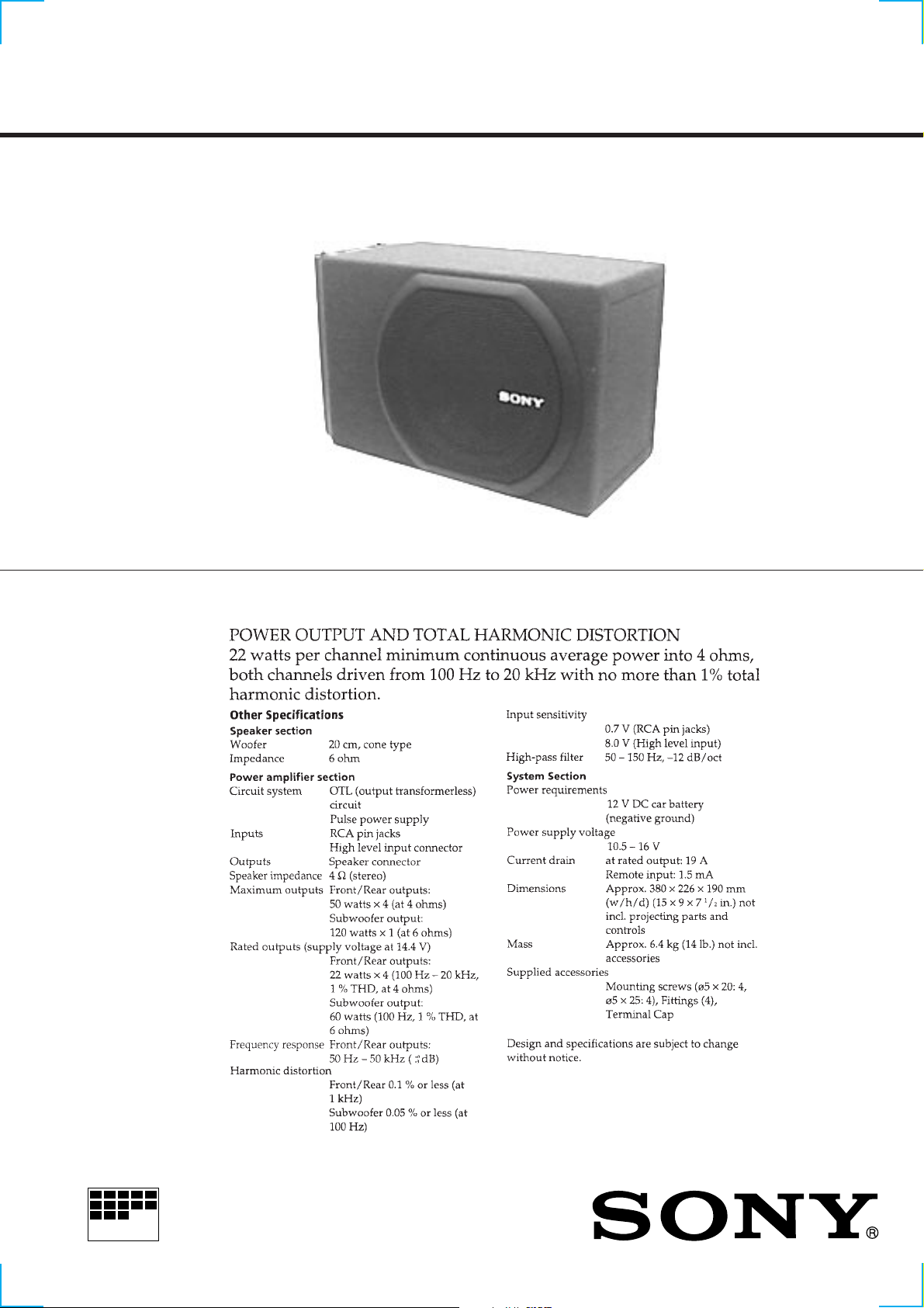
XS-AW850
SERVICE MANUAL
SPECIFICATIONS
US Model
MICROFILM
5 CHANNEL ACTIVE SUBWOOFER
– 1 –
TABLE OF CONTENTS
Specifications ............................................................................. 1
1. GENERAL....................................................................... 2
2. DISASSEMBLY
2-1. Amplifier Assembly......................................................4
2-2. Main Board ...................................................................4
2-3. DC Fan Motor...............................................................5
3. DIAGRAMS
3-1. IC Block Diagrams .......................................................6
3-2. Printed Wiring Board....................................................7
3-3. Schematic Diagram.......................................................9
4. EXPLODED VIEW...................................................... 11
5. ELECTRICAL PARTS LIST.................................... 13
SECTION 1
GENERAL
This section is extracted from
instruction manual.
– 2 –
– 3 –
SECTION 2
5
DISASSEMBLY
Note: Follow the disassembly procedure in the numerical order given.
2-1. AMPLIFIER ASSEMBLY
1
Two tapping screws
(4x30)
2
Two tapping screws
(4x30)
5
Amplifier assembly
3
Wire (White)
2-2. MAIN BOARD
4
Four screws
(BTP 3x8)
1
Fuse (F901)
(Brade type)
4
Wire (Red)
Heat sink (MAIN)
3
T wo screws
(BTP 3x8)
8
Main board
9
7
Five screws
(BTP 3x10)
Pull out a Wire.
6
Three screws
(BTP 3x10)
– 4 –
0
Panel
2
T wo screws
(BTP 3x8)
 Loading...