

Page 1
XR-M500R/M550
SERVICE MANUAL
Ver 1.1 2002.09
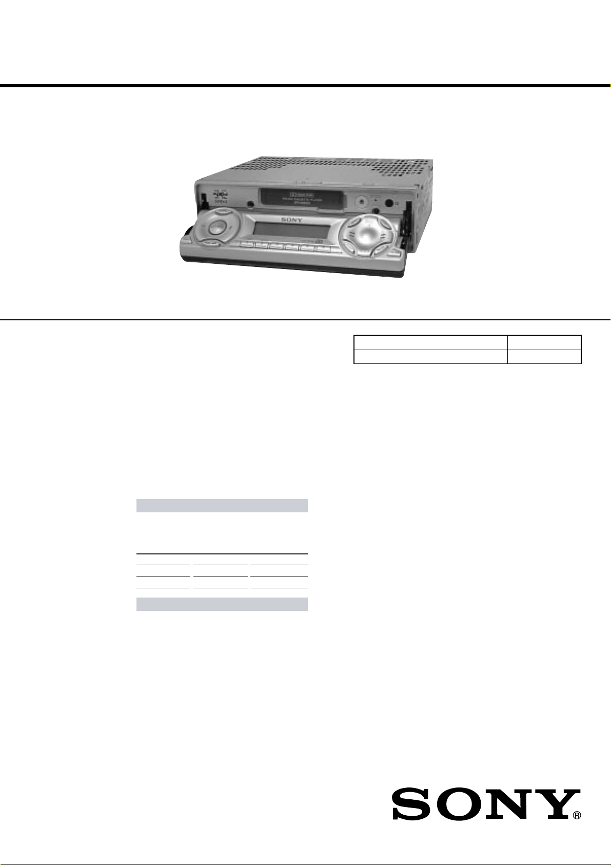
Photo: XR-M550
Dolby noise reduction manufactured under license from
Dolby Laboratories Licensing Corporation.
“DOLBY” and the double-D symbol ; are trademarks
of Dolby Laboratories Licencing Corporation.
SPECIFICATIONS
AUDIO POWER SPECIFICATIONS (US model)
POWER OUTPUT AND TOTAL HARMONIC DISTORTION
19 watts per channel minimum continuous average power into
4 ohms, 4 channels driven from 20 Hz to 20 kHz with no more
than 1% total harmonic distortion.
US Model
Canadian Model
XR-M550
AEP Model
UK Model
XR-M500R
Model Name Using Similar Mechanism NEW
T ape Transport Mechanism Type MG-25E-136
Other specifications
Cassette player section
Tape track 4-track 2-channel stereo
Wow and flutter 0.08 % (WRMS)
Frequency response 30 – 20,000 Hz
Signal-to-noise ratio
Dolby NR off
61 dB
58 dB
87.5 – 107.9 MHz (XR-M550)
10.7 MHz/450kHz
8 dBf
75 dB at 400 kHz
IV
Dolby B NR
67 dB
64 dB
Cassette type
TYPE II,
TYPE I
Tuner section
FM
Tuning range 87.5 – 108.0 MHz (XR-M500R)
Antenna terminal External antenna connector
Intermediate frequency
Usable sensitivity
Selectivity
FM/AM (MW/LW) CASSETTE CAR STEREO
Signal-to-noise ratio 66 dB (stereo),
Harmonic distortion at 1 kHz
Separation 35 dB at 1 kHz
Frequency response 30 – 15,000 Hz
MW/LW (XR-M500R)
Tuning range MW: 531 – 1,602 kHz
Aerial terminal External aerial connector
Intermediate frequency 10.7 MHz/450 kHz
Sensitivity MW: 30 µV
AM (XR-M550)
Tuning range 530 – 1,710 kHz
Antenna terminal External antenna connector
Intermediate frequency 10.7 MHz/450 kHz
Sensitivity 30 µV
72 dB (mono)
0.6 % (stereo),
0.3 % (mono)
LW: 153 – 279 kHz
LW: 40 µV
– Continued on next page –
9-870-088-13 Sony Corporation
2002I0500-1 e Vehicle Company
C 2002.09 Published by Sony Engineering Corporation
Page 2

Power amplifier section
Outputs Speaker outputs
Speaker impedance 4 – 8 ohms
Maximum power output 50 W × 4 (at 4 ohms)
General
Outputs Audio output (2) (M500R)
Inputs Telephone ATT control
Tone controls Bass ±9 dB at 100 Hz
Power requirements 12 V DC car battery
Dimensions Approx. 178
Mounting dimensions Approx. 182 × 53 × 163 mm
Mass Approx. 1.3 kg (2lb. 14 oz.)
Supplied accessories Card remote commander
Design and specifications are subject to change
without notice.
Audio output (3) (M550)
Power aerial relay control
lead
Power amplifier control
lead
lead
Illumination control lead
Treble ±9 dB at 10 kHz
(negative earth)
1
(7
/
(w/h/d)
1
(7
/
(w/h/d)
RM-X96 (XR-M500R)
RM-X94 (XR-M550)
Parts for installation and
connections (1 set)
× 2 × 7
8
× 2
4
× 50 × 182 mm
4
/1 in.)
1
1
/
× 6
/2 in.)
8
TABLE OF CONTENTS
1. SERVICING NOTES ............................................... 3
2. GENERAL
Location of Controls (XR-M500R) ................................ 4
Setting the Clock ............................................................. 4
Changing the Sound and Display Setting....................... 4
Locations of Controls (XR-M550) ................................. 5
Setting the Clock ............................................................. 5
Changing the Sound and Display Setting....................... 5
Installation (XR-M500R)................................................ 6
Installation (XR-M550) .................................................. 7
Connections (XR-M500R).............................................. 8
Connections (XR-M550) ................................................ 12
3. DISASSEMBLY ......................................................... 15
4. ASSEMBLY................................................................. 19
5. MECHANICAL ADJUSTMENTS ....................... 24
6. ELECTRICAL ADJUSTMENTS
Tape Deck Section .......................................................... 24
Tuner Section .................................................................. 25
7. DIAGRAMS
7-1. Block Diagram – TUNER/TAPE Section – .................. 27
7-2. Block Diagram – MAIN Section – ................................ 28
7-3. Block Diagram
– DISPLAY/BUS CONTROL Section – ....................... 29
7-4. Block Diagram – POWER SUPPLY Section – ............. 30
7-5. Note for Printed Wiring Boards and
Schematic Diagrams ....................................................... 31
7-6. Printed Wiring Board
– MAIN Board (Component Side) – .............................. 32
7-7. Printed Wiring Board
– MAIN Board (Conductor Side) – ................................ 33
7-8. Schematic Diagram – MAIN Board (1/4) – .................. 34
7-9. Schematic Diagram – MAIN Board (2/4) – .................. 35
7-10. Schematic Diagram – MAIN Board (3/4) – .................. 36
7-11. Schematic Diagram – MAIN Board (4/4) – .................. 37
7-12. Printed Wiring Board –SUB Board – ............................ 38
7-13. Schematic Diagram – SUB Board – .............................. 39
7-14. Printed Wiring Board – DISPLAY Board – .................. 40
7-15. Schematic Diagram – DISPLAY Board – ..................... 41
7-16. IC Pin Function Description ........................................... 44
8. EXPLODED VIEWS................................................ 51
9. ELECTRICAL PARTS LIST ............................... 55
Flexible Circuit Board Repairing
• Keep the temperature of the soldering iron around 270 ˚C dur-
ing repairing.
• Do not touch the soldering iron on the same conductor of the
circuit board (within 3 times).
• Be careful not to apply force on the conductor when soldering
or unsoldering.
Notes on chip component replacement
• Never reuse a disconnected chip component.
• Notice that the minus side of a tantalum capacitor may be dam-
aged by heat.
2
Page 3

SECTION 1
m
r
R625
R626
SERVICING NOTES
PRECAUTION ON OPEN/CLOSE FRONT PANEL
The front panel opens to the bottom of main unit.
In performing the repair, place the main unit on the base having
the height exceeding 1 cm.
front panel
XR-M500R/M550
( SIDE VIEW)
base
1c
Open the front panel by supplying the power through the following steps:
1. Disconnect the motor connector (CN501) from main board.
2. Supply the power to the motor.
Voltage : 9 V
Violet wiring : MOTOR –
Gray wiring : MOTOR +
gray wiring
–
+
violet
wiring
MODEL IDENTIFICATION
There are four types of main board in according of destination for
XR-M500R.
– MAIN BOARD (Componet Side) –
R719
IC601
R720
– MAIN BOARD (Conductor Side) –
connecto
(CN501)
R625 R626 R719 R720 Indicated language
TYPE A aa ××
TYPE B ××aa
TYPE C × aa × English, German
TYPE D a ××a
English, Spanish,
Swedish, Portuguese
German, Italian, Dutch,
French
English, Polish, Czeck,
Turkish
TYPE A, B, C, or D can also be identified from the front panel
display language.
For a switching method of display language, see page 4.
3
Page 4
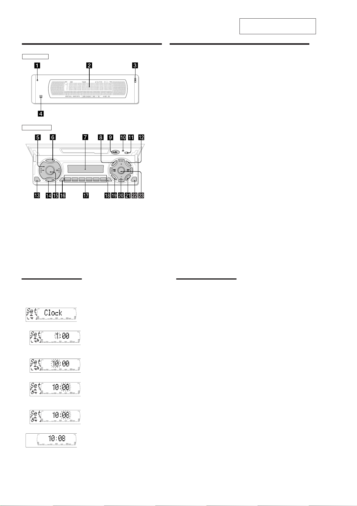
(XR-M500R)5(XR-M550)
Location of controls
Security side
Operation side
T
Y
P
P
S
L
D
SOURCE
OFF
M
O
REP SHUF
123 456
D
E
XR-M500R
SECTION 2
GENERAL
The corresponding buttons of the unit
control the same functions as those on
the card remote commander.
10 Reset b utton 8
2 Main display window
3 OPEN button 38
4qa Receptor for the card remote
commander
5 Volume adjust buttons
6 DSPL/PTY (display mode change/
programme type) button
7 Sub display window
8 MENU button
Z (eject) button 11
9
qs LIST button
qd OFF button*
qf MODE button
qg SOURCE (TUNER/TAPE/CD/MD) button
qh AF button 16, 18
qj Number buttons
During radio reception:
During tape playback:
LIST
U
DISC
N
E
M
D-BASS
SOUND
R
E
T
N
DISC
TAAF
E
CLOSE
During CD/MD playback:
9
Preset number select
13, 14, 17, 33, 34
(1) REP 12
(1) REP 28
(2)
SHUF 28
This section is extracted from
instruction manual.
qk TA button 16, 17, 18
ql SOUND button
w; PRST/DISC +/– (cursor up/down) buttons
SEEK/AMS –/+ (cursor left/right) buttons
13
wa ENTER button
ws CLOSE button
wd D-BASS button
* Warning when installing in a car
without ACC (accessory) position on
the ignition key switch
Be sure to press (OFF) on the unit for
two seconds to turn off the clock display
after turning off the engine.
When you press (OFF) only momentarily,
the clock display does not turn off and this
causes battery wear.
6
Setting the clock
The clock uses a 24-hour digital indication.
Example: To set the clock to 10:08
1 Press (MENU), then M or m repeatedly
until “Clock” appears.
1 Press (ENTER).
The hour indication flashes.
2 Press M or m to set the hour.
3 Press ,.
The minute indication flashes.
4 Press M or m to set the minute.
Tips
• You can use the convenient CT function to set
the clock automatically (page 20).
• When the D.Info mode is set to “on,” the time is
always displayed (except for some functions of
SA mode) (page 23).
Changing the sound and display settings
The following items can be set:
Set (Setting)
•Clock (page 10).
•CT (Clock Time) (page 20).
•Beep — to turn the beep sound on or off.
•RM (Rotary Commander) — to change the
operative direction of the rotary commander.
— Select “norm” to use the rotary
commander as the factory-set position.
— Select “rev” when you mount the rotary
commander on the right side of the
steering column.
•English/Spanish/Portuguese/Swedish — to
change the display language to English,
Spanish, Portuguese or Swedish.
Dis (Display)
•D.Info (Dual Information) — to display the
clock and the play mode simultaneously (on),
or to display the information alternately (off).
•SA (Spectrum Analyzer) — to change the
display pattern of the equalizer display
(page 25).
•Dimmer — to change the brightness of the
display (When the Illumination terminal
connected).
— Select “on” to dim the display.
— Select “off” to deactivate Dimmer.
•Contrast — to adjust the contrast if the
indications in the display are not
recognisable because of the unit’s installed
position.
•M.Dspl (Motion Display) — to turn the
motion display on or off.
•A.Scrl (Auto Scroll) (page 27).
continue to next page t
1 Press (MENU).
2 Press M or m repeatedly until the desired
item appears.
Each time you press m, the item changes as
follows:
Example
Clock t CT t Beep t RM t English/
Spanish/Portuguese/Swedish t D.Info t SA
t Dimmer t Contrast t M.Dspl*
1
*
When no CD or MD is playing, this item will
not appear.
2
*
When the radio is off, or when no tape, CD,
or MD is playing, this item will not appear.
Note
The displayed item will differ depending on the
source.
Tip
You can easily switch among categories (“Set,”
“Snd” (Sound), “P/M” (Play Mode) and “Dis”) by
M
or m for two seconds.
pressing
3 Press , to select the desired setting
(Example: on or off).
4 Press (ENTER).
After the mode setting is complete, the
display returns to normal playback mode.
1
t A.Scrl*
7
2
2 Press (ENTER).
The clock starts.
10
4
23
24
Page 5
Page 6
(XR-M500R)7(XR-M550)
Installation
Instalación
Montering
Instalação
Precautions
•If you mount other Sony equipment with this
unit, it is better to mount this unit in the lower
position.
•There must be a distance of at least 15 cm
between the cassettes slot of the unit and shift
lever to insert cassette easily. Choose the
installation location carefully so the unit does
not interfere with gear shifting and other driving
operations.
•When the front panel is open, a portion of it will
extend down from the unit. When you install the
unit, make sure that this portion of the front
panel is not obstructed in its open position (by
the ashtray, for example).
•Choose the installation location carefully so that
the unit will not interfere with normal driving
operations.
•Avoid installing the unit in areas subject to dust,
dirt, excessive vibration, or high temperatures,
such as in direct sunlight or near heater ducts.
•Use only the supplied mounting hardware for a
safe and secure installation.
Mounting angle adjustment
Adjust the mounting angle to less than 20°.
Precauciones
•Si monta otro equipo Sony con esta unidad, es
preferible montar esta unidad en la posición más
baja.
•Para que sea posible insertar la cinta con
facilidad, debe haber una distancia de al menos
15 cm entre la ranura de inserción de cintas de la
unidad y la palanca de cambios.
Instale la unidad en un lugar que no entorpezca
las operaciones de cambio de marchas o de
conducción en general.
•Cuando el panel frontal está abierto, una parte
de él sobresaldrá de la unidad. Cuando instale la
unidad, compruebe que dicha parte del panel
frontal no queda obstruida en la posición de
apertura (debido al cenicero, por ejemplo).
•Elija cuidadosamente el lugar de montaje de
forma que la unidad no interfiera las funciones
normales de conducción.
•Evite instalar la unidad donde pueda quedar
sometida a altas temperaturas, como a la luz
solar directa o al aire de calefacción, o a polvo,
suciedad, o vibraciones excesivas.
•Para realizar una instalación segura y firme,
utilice solamente la ferretería de montaje
suministrada.
Ajuste del ángulo de montaje
Ajuste el ángulo de montaje a menos de 20°.
15
cm
Säkerhetsföreskrifter
•Om du monterar annan Sony-utrustning till
denna enhet är det bäst att montera denna enhet
i det undre läget.
•För att du ska kunna sätta i och ta ut bandet
måste avståndet vara minst 15 cm mellan
kassettfacket på enheten och växelspaken. När
du installerar enheten väljer du en plats så att
enheten inte är i vägen när du kör.
•När frontpanelen är öppen befinner sig en liten
del av den under enhetens bottenplan. Se till att
du installerar enheten så att den här delen går fri
(från t.ex. askkoppen) när frontpanelen är
öppen.
•Var noga när du väljer var i bilen du monterar
bilstereon, så att den inte sitter i vägen när du
kör.
•Montera inte bilstereon där den utsätts för
värme,
t ex solsken eller varmluft, eller där den utsätts
för damm, smuts och/eller vibrationer.
•Använd endast de medföljande
monteringstillbehören för att vara säker på att
bilstereon monteras på ett säkert och korrekt
sätt.
Tillåten monteringsvinkel
Monteringsvinkeln får inte vara större än 20
grader.
Extended portion of the front panel.
Parte sobresaliente del panel frontal.
Utskjutande del av frontpanelen.
Parte extensível do painel frontal.
8.5 mm
15.5 mm
Precauções
•É preferível montar este aparelho na posição
mais baixa, se quiser montar simultaneamente
outros equipamentos da Sony.
•Para colocar com facilidade a cassete, deve haver
uma distância de pelo menos 15 cm entre a
ranhura de introduçäo da cassete e a alavanca
das mudanças.
Escolha o local de instalaçäo de forma a que o
aparelho näo interfira com as mudanças de
velocidade ou com as outras manobras de
conduçäo.
•Quando o painel frontal estiver aberto, pode
puxar a parte extensível baixo. Quando instalar
a unidade, verifique se essa parte do painel
frontal não está presa na posição aberta (pelo
cinzeiro, por exemplo).
•Escolha com cuidado um local apropriado para
a montagem do aparelho, para que este não
interfira com as manobras necessárias à
condução do veículo.
•Evite instalar o aparelho onde possa estar sujeito
a altas temperaturas, como em locais expostos
directamente à luz do sol, ao ar quente dos
aquecimentos, ou sujeitos a pó, sujidade ou
vibração excessiva.
•Para efectuar uma instalação segura utilize
unicamente o hardware de montagem fornecido.
Ajuste do ângulo de montagem
Ajuste o ângulo de montagem a menos de 20°.
Installation in the dashboard Instalación en el salpicadero Montera på instrumentbrädan Instalação no tablier
1 2 3
Bend these claws outward
for a tight fit, if necessary.
Si es necesario, doble estas
1
Note
To prevent malfunction, install only with the supplied
5
.
screws
Reset button
When the installation and connections are
complete, be sure to press the reset button with a
ballpoint pen, etc.
uñas hacia afuera para que
encaje firmemente.
För att få en tät passning
böj dessa flikar vid behov.
Se necessário, dobre as
unhas para prender melhor.
Nota
Para evitar fallos de funcionamiento, realice la
instalación únicamente con los tornillos suministrados
5
.
Botón de restauración
Cuando finalice la instalación y las conexiones,
cerciórese de pulsar el botón de restauración con
un bolígrafo, etc.
4
Dashboard
Salpicadero
Instrumentbräda
Tablier
1
5
5
7
7
7
5
Observera
Använd bara de medföljande skr uvarna
undviker du onödiga fel.
Nollställningsknappen
Kom ihåg att använda en penna eller något annat
spetsigt föremål för att trycka på
nollställningsknappen när anslutningen och
monteringen är klar.
4
With the UP marking up
Con la marca UP hacia arriba
Med märkningen UP vänd uppåt
Com a marca UP para cima
5
, så
Nota
Para evitar avarias, instale o aparelho apenas com os
parafusos fornecidos
Botão de reinicialização
Quando terminar a instalação e as ligações, não se
esqueça de carregar no botão de reinicialização
com a ponta de uma caneta, esferográfica, etc.
5
.
Fire wall
Panel cortafuegos
Brandsäker
mellanvägg
Painel corta-fogo
2
3
6
Page 7

Page 8

(XR-M500R)
Connections
Cautions
•This unit is designed for negative earth 12 V DC
operation only.
•Be careful not to pinch any wires between a
screw and the body of the car or this unit or
between any moving parts such as the seat
railing, etc.
•Connect the power connecting cord 8 to the
unit and speakers before connecting it to the
auxiliary power connector.
•Run all earth wires to a common earth point.
•Connect the yellow cord to a free car circuit
rated higher than the unit’s fuse rating. If you
connect this unit in combination with other
stereo components, the car circuit they are
connected to must be rated higher than the sum
of the individual components’ fuse rating. If
there are no car circuits rated as high as the
unit’s fuse rating, connect the unit directly to the
battery. If no car circuits are available for
connecting this unit, connect the unit to a car
circuit rated higher than the unit’s fuse rating in
such a way that if the unit blows its fuse, no
other circuits will be cut off.
Warning when installing in a car
without ACC (accessory) position
on the ignition key switch
Be sure to press (OFF) on the unit for two
seconds to turn off the clock display after
turned off the engine.
When you press (OFF) momentarily, the clock
display does not turn off and this causes battery
wear.
Conexiones
Precauciones
•Esta unidad ha sido diseñada para alimentarse
con 12 V CC, negativo a masa, solamente.
•Tenga cuidado de no atrapar ningún cable entre
algún tornillo y la carrocería del automóvil o
esta unidad o entre las partes móviles, como por
ejemplo los raíles del asiento, etc.
•Conecte el cable de conexión de alimentación 8
a la unidad y los altavoces antes de conectarlo al
conector de alimentación auxiliar.
•Conecte todos los conductores de puesta a
masa a un punto común.
•Conecte el cable amarillo a un circuito libre del
automóvil de potencia nominal superior a la del
fusible de la unidad. Si conecta esta unidad en
combinación con otros componentes estéreo, la
potencia nominal del circuito del automóvil a los
que dichos componentes estén conectados debe
ser superior a la suma de la potencia nominal
del fusible de los componentes. Si no existen
circuitos de automóvil de potencia nominal tan
alta como la del fusible de la unidad, conecte
ésta directamente a la batería. Si no hay circuitos
de automóvil disponibles para conectar esta
unidad, conecte la misma a un circuito de
automóvil de potencia nominal superior a la del
fusible de la unidad de forma que no se
desactiven otros circuitos si el fusible de dicha
unidad se funde.
Advertencia sobre la instalación
en un automóvil que no
disponga de posición ACC
(accesorios) en el interruptor de
la llave de encendido
Asegúrese de pulsar (OFF) en la unidad
durante dos segundos para desactivar la
indicación del reloj una vez apagado el motor.
Si pulsa (OFF) momentáneamente, la indicación
del reloj no se desactivará y esto causará el
desgaste de la batería.
Anslutning
Säkerhetsföreskrifter
•Denna bilstereo är endast avsedd för anslutning
till ett negativt jordat, 12 V bilbatteri.
•Var noga med att inga kablar kläms mellan
någon skruv eller att de blir klämda mellan
rörliga delar som t.ex. bilsätet.
•Anslut strömkabeln 8 till enheten och
högtalarna innan du ansluter den till den yttre
strömanslutningen.
•Dra samtliga jordledningar till en och samma
jordningspunkt.
•Anslut den gula kabeln till en ledig bilkrets med
ett högre amperetal än enhetens. Om du kopplar
både denna enhet och andra stereokomponenter
till en och samma bilkrets, måste den bilkrets de
kopplas till ha en högre ampere än summan av
de enskilda delarnas amperestyrka. Om det inte
finns några bilkretsar med en så hög
amperestyrka som enhetens ska du ansluta
enheten direkt till batteriet. Om inga bilkretsar
finns för anslutning till enheten ska du ansluta
enheten till en bilkrets med ett högre amperetal
än enhetens säkring, så att det är denna som går
i stället för bilens.
Var försiktig när du gör
installationen i en bil där
tändningslåset saknar
tillbehörsläge (ACC)
Glöm inte att trycka på (OFF) på enheten
under två sekunder för att stänga av klockans
teckenfönster efter det att du har stängt av
motorn.
Om du bara trycker på (OFF) ett kort ögonblick
slocknar inte klockans teckenfönster vilket kan
leda till att batteriet laddas ur.
Ligações
Cuidado
•Este aparelho foi concebido para funcionar
somente com corrente contínua de 12 V com
negativo à massa.
•Tenha cuidado para que os fios não fiquem
entalados entre os parafusos e a carroçaria do
automóvel ou a caixa do aparelho, nem entre as
peças móveis, por exemplo, as calhas dos
bancos, etc.
•Ligue o cabo de alimentação de corrente 8 ao
aparelho e aos alifalantes antes de o ligar ao
conector de corrente auxiliar.
•Ligue todos os cabos de massa num ponto de
massa comum.
•Ligue o cabo amarelo a um circuito eléctrico
livre do automóvel, cuja potência nominal seja
superior à dos fusíveis do aparelho. Se ligar este
aparelho em série com outros componentes
estéreo, a potência nominal do circuito eléctrico
do automóvel onde os ligar tem de ser superior
à soma da potência nominal dos fusíveis de
todos os componentes individuais. Se não
houver nenhum circuito eléctrico do automóvel
com uma potência nominal tão elevada como a
dos fusíveis do aparelho, ligue-o directamente à
bateria. Se não estiver disponível nenhum
circuito eléctrico do automóvel para ligação
deste aparelho, ligue-o a um circuito eléctrico do
automóvel com uma potência nominal superior
à dos fusíveis do aparelho, de tal modo que, se o
aparelho rebentar os fusíveis respectivos,
nenhum outro circuito seja cortado.
Aviso sobre a instalação num
automóvel sem posição ACC
(acessórios) na chave de ignição
Verifique se carregou em (OFF) no aparelho
durante dois segundos para desactivar o visor
do relógio depois de ter desligado o motor.
Se carregar ligeiramente em (OFF), não desactiva
o visor do relógio o que provoca o desgaste da
bateria.
Notes of connection example
Notes on the control leads
•
The power aerial control lead (blue) supplies +12 V
DC when you turn on the tuner or when you
activate the ATA (Automatic Tuner Activation), AF
(Alternative Frequency) or the TA (Traffic
Announcement) function.
•
A power aerial without a relay box cannot be used
with this unit.
•
When your car has a built-in FM/MW/LW aerial in
the rear/side glass, it is necessary to connect the
power aerial control lead (blue) or the accessory
power input lead (red) to the power terminal of the
existing aerial booster. For details, consult your
dealer.
Warning
If you have a power aerial without a relay box,
connecting this unit with the supplied power
connecting cord
Memory hold connection
When the yellow power input lead is connected,
power will always be supplied to the memory circuit
even when the ignition switch is turned off.
Notes on speaker connection
•
•
•
•
•
8
may damage the aerial.
Before connecting the speakers, turn the unit off.
Use speakers with an impedance of 4 to 8 ohms, and
with adequate power handling capacities.
Otherwise, the speakers may be damaged.
Do not connect the terminals of the speaker system
to the car chassis, and do not connect the terminals
of the right speaker with those of the left speaker.
Do not attempt to connect the speakers in parallel.
Do not connect any active speakers (with built-in
amplifiers) to the speaker terminals of the unit.
Doing so may damage the active speakers. Be sure
to connect passive speakers to these terminals.
Notas de ejemplo de conexiones
Notas sobre cables de control
• El cable de control (azul) de la antena motorizada
suministra + 12 V CC al activar el sintonizador o la
función ATA (activación automática del
sintonizador), AF (frecuencias alternativas) o TA
(anuncios de tráfico).
• Con esta unidad no podrá utilizarse una antena
motorizada sin caja de relés.
• Si el automóvil dispone de antena de FM/MW/LW
incorporada en el cristal trasero/lateral, será
necesario conectar el cable de control de antena
motorizada (azul) o el cable de entrada de
alimentación accesoria (rojo) al terminal de potencia
del amplificador de antena existente. Para más
información, consulte con el proveedor.
Advertencia
Si dispone de una antena motorizada sin dispositivo
de relé, la conexión de esta unidad con el cable de
conexión de alimentación
dañar la antena.
Conexión para protección de la memoria
Si conecta el cable de entrada de alimentación
amarillo, el circuito de la memoria recibirá siempre
alimentación, incluso aunque ponga la llave de
encendido en la posición de apagado.
Notas sobre la conexión de los altavoces
•
Antes de conectar los altavoces, desconecte la
alimentación de la unidad.
•
Utilice altavoces con una impedancia de 4 a
8 ohmios, y con la potencia máxima admisible
adecuada, ya que de lo contrario podría dañarlos.
•
No conecte los terminales del sistema de altavoces al
chasis del automóvil, ni los del alta voz izquierdo a
los del derecho.
•
No intente conectar los altavoces en paralelo.
•
No conecte altavoces activos (con amplificadores
incorporados) a los terminales de altavoces de la
unidad. Si lo hiciese, podría dañar tales altavoces.
Por lo tanto, cerciórese de conectar altavoces pasivos
a estos terminales.
8
suministrado puede
Att observera angående
anslutningsexemplen
Att observera angående de olika styrkablarna
•
Motorantennens styrkabel (blå) leder + 12 volts
likström när kanalväljaren slås på eller när
radiomottagningsautomatik ATA, mottagning av
alternativa frekvenser AF eller mottagning av
trafikmeddelanden TA aktiverats.
•
En motorantenn utan styrrelädosa kan inte anslutas
till denna bilstereo.
•
Om bilen har en FM/MW/LW-antenn som är inbyggd
i sido- eller bakrutan, måste du ansluta
motorantennens styrkabel (blå) eller
tilbehörsströmkabeln (röd) till strömterminalen på
antennförstärkaren. Din återförsäljare kan ge dig
mer information.
Varning
Om du har en motorantenn utan relädosa kan
antennen skadas om du ansluter enheten med den
medföljande strömkabeln
Anslutning för minnesstöd
När du anslutit den gula, ingående strömkabeln
försörjs minneskretsen med ström hela tiden, även när
tändlåset slås ifrån.
Att observera angående högtalarnas anslutning
•
Slå av bilstereon innan du ansluter högtalarna.
•
Anslut endast högtalare, vars impedans varierar från
4 till 8 ohm och som har tillräcklig
effekthanteringskapacitet för att skydda högtalar na
mot skador.
•
Anslut inte något av högtalaruttagen till bilens
chassi. Anslut inte heller uttagen på höger högtalare
till uttagen på vänster högtalare.
•
Anslut inte högtalarna parallellt.
•
Anslut inte aktiva högtalare (med inbyggda slutsteg)
till bilstereons högtalaruttag, eftersom de kan skada
de aktiva högtalarna. Var noga med att bara ansluta
passiva högtalare till dessa uttag.
8
.
Notas sobre o exemplo de
ligação
Notas sobre os fios de controlo
• O fio de controlo da antena eléctrica (azul) fornece
+12 V CC quando ligar o sintonizador ou quando
activar as funções ATA (Activação automática do
sintonizador), AF (frequência alternativa) ou TA
(Informações de trânsito).
• Não pode utilizar uma antena eléctrica sem caixa de
relé com este aparelho.
•
Se o seu automóvel tiver uma antena de FM/MW/LW
montada no vidro traseiro/lateral, tem de ligar o fio
de controlo da antena eléctrica (azul) ou o fio de
entrada de alimentação para os acessór ios
(vermelho) ao terminal de alimentação do
intensificador do sinal da antena existente.
Advertência
Se a antena eléctrica não tiver uma caixa de relé, o
facto de ligar este aparelho com o cabo de
alimentação
8
fornecido, pode provocar danos na
antena.
Ligação para alimentação contínua da memória
Quando o fio amarelo de entrada de alimentação for
ligado, os circuitos de memória ficarão com
alimentação continua, mesmo se a chave de ignição
estiver desligada.
Notas sobre a ligação dos altifalantes
•
Antes de ligar os altifalantes, desligue o aparelho.
•
Utilize altifalantes com impedância de 4 a 8 ohm, e
com potência máxima admissível adequada. Caso
contrário, os altifalantes poderão sofrer avarias.
•
Não ligue os terminais do sistema de altifalantes ao
chassis do automóvel, e não ligue os terminais do
altifalante direito aos terminais do altifalante
esquerdo.
•
Não tente ligar os altifalantes em paralelo.
•
Não ligue nenhum sistema de altifalantes activos
(com amplificadores incorporados) aos terminais dos
altifalantes do aparelho. Caso o faça, poderá avariar
o sistema de altifalantes activos. Portanto, não se
esqueça de ligar altifalantes passivos a estes
terminais.
8
Page 9
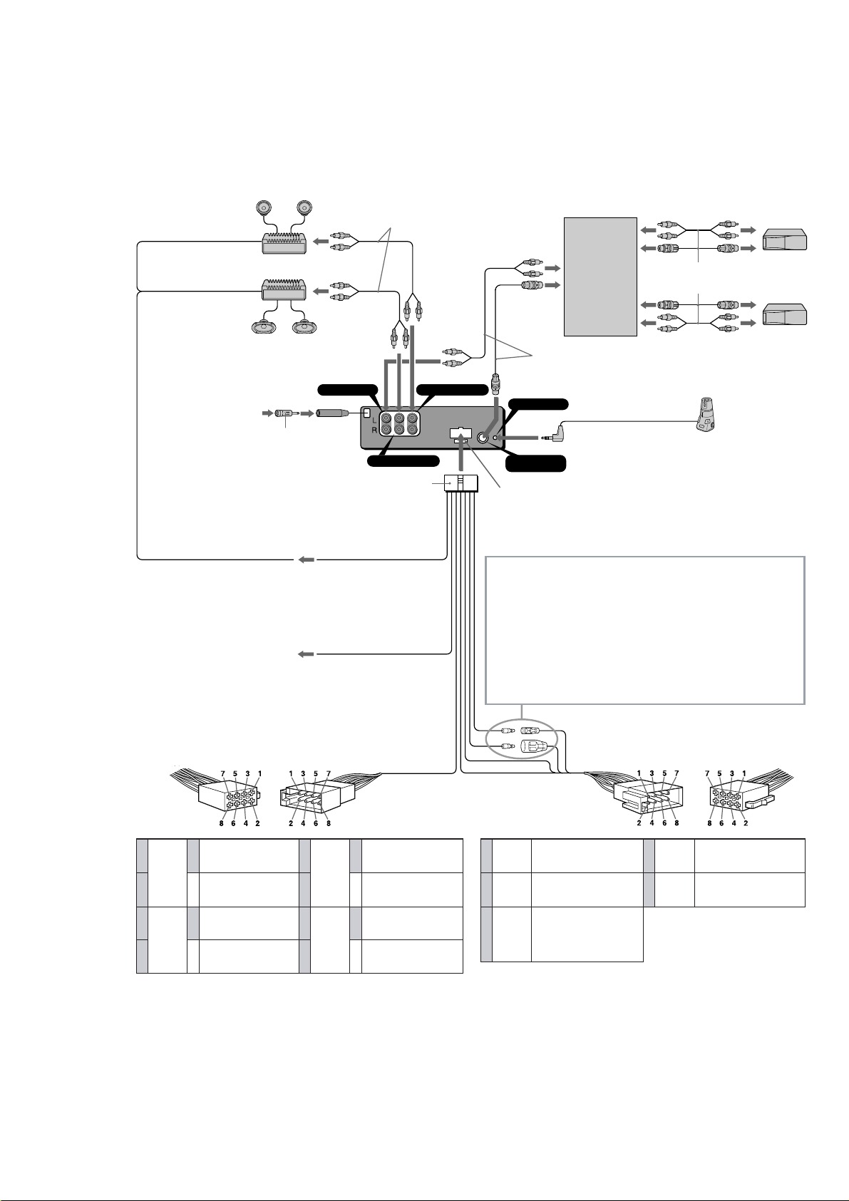
Connection example
1
*
Note for the aerial connecting
If your car aerial is an ISO (International
Organisation for Standardisation) type, use the
supplied adaptor
First connect the car aerial to the supplied adaptor,
then connect it to the aerial jack of the master unit.
2
*
RCA pin cord (not supplied)
6
to connect it.
from car aerial*
de la antena del automóvil*
från bilantenn*
da antena do automóvel*
to the interface cable of a car telephone
al cable de interfaz de un teléfono para
automóvil
till mobiltelefonens gränssnittskabel
Ao cabo de interface de um telefone para
automóvel
1
1
1
1
Ejemplo de conexiones
1
*
Nota sobre la conexión de la antena
Si la antena del automóvil es del tipo ISO
(International Organization for Standardization),
emplee el adaptador suministrado
conectarla.
En primer lugar, conecte la antena del automóvil al
adaptador suministrado y, a continuación, a la
toma de antena de la unidad principal.
*
Cable con clavijas RCA (no suministrado)
*
BUS AUDIO IN AUDIO OUT FRONT
6
AUDIO OUT REAR
Blue/white striped
Con raya azul/blanca
AMP REM
Max. supply current 0.3 A
Corriente máx. de alimentación de 0,3 A
Maximal strömtillförsel 0,3 A
Corrente máxima de 0,3 A
ATT
Blå/vit-randig
Azul com listras brancas
Light blue
Azul celeste
Ljusblå
Azul claro
Anslutningarna enligt exemplet
1
*
Angående antennanslutning
Om motorantennen är av ISO-typ (International
6
para
2
8
Organization for Standardization), använder du
medföljande adapter
Anslut först motorantennen till medföljande
adapter och därefter till antennuttaget på
huvudenheten.
2
Kabel med RCA-kontakter (medföljer inte)
*
Fuse (10 A)
Fusible (10 A)
Säkring (10 A)
Fusivel (10 A)
WARNING
Auxiliary power connectors may vary depending on
the car. Be sure to check the power connection
diagram. Improper connections may damage your
car. If the supplied power connecting cord can not
be used with your car, consult your nearest Sony
dealer.
ADVERTENCIA
Los conectores de alimentación auxiliar pueden
variar en función del automóvil. Asegúrese de
consultar el diagrama de conexión de alimentación.
Las conexiones incorrectas pueden dañar el
automóvil. Si no es posible utilizar con el automóvil
el cable de conexión de alimentación suministrado,
póngase en contacto con el proveedor Sony más
próximo.
6
för att ansluta den.
Supplied to XA-C30
Suministrado con el XA-C30
Medföljer XA-C30
Fornecido para o XA-C30
REMOTE IN
BUS
CONTROL IN
Source selector
(not supplied)
Selector de fuente
(no suministrado)
Väljare för ljudkälla
(medföljer inte)
Selector de fonte
(não fornecido)
XA-C30
Insert with the cord upwards.
Insertar con el cable hacia arriba.
Sätt in med kabeln vänd uppåt.
Inserir com o fio virado para cima.
Exemplo de ligações
1
*
Nota referente à ligação da antena
Se a antena do automóvel for uma antena de tipo
ISO (International Organization for
Standardization), utilize o adaptador fornecido
para fazer a ligação respectiva.
Ligue primeiro a antena do automóvel ao
adaptador fornecido e depois à ficha tipo jack de
antena do sistema principal.
2
*
Cabo de terminais RCA (não fornecido)
Supplied to the CD/MD changer
Suministrado con el cambiador de CD/MD
Medföljer CD/MD-växlaren
Fornecido para o permutador de CD/MD
Rotary commander RM-X4S (not supplied)
Mando rotativo RM-X4S (no suministrado)
Vridkontroll RM-X4S (medföljer inte)
Comando rotativo RM-X4S (não fornecido)
VARNING
Typen av yttre strömanslutning varierar från bil till
bil. Kontrollera strömanslutningsschemat som
medföljer enheten så att du ansluter på rätt sätt.
Felaktig anslutning kan skada bilen. Kontakta
närmaste Sony-återförsäljare om den medföljande
strömkabeln inte passar till din bil.
ADVERTÊNCIA
Os conectores de corrente auxiliares podem variar
de carro para carro. Não se esqueça de verificar o
diagrama de ligação de corrente fornecido com o
aparelho. As ligações mal executadas podem
danificar o seu carro. Se não puder utilizar o cabo
de alimentação fornecido no seu carro, contacte o
agente Sony da sua zona.
6
to a car’s speaker connector
a un conector de altavoces del automóvil
till bilens högtalaranslutning
ao conector de um altifalante do automóvel
Speaker, Rear , Right
Altavoz, parte posterior, derecho
Purple
Púrpura
Violett
Violeta
Grey
Gris
Grå
Cinzento
+
Högtalare, bakre, höger
Altifalante, Parte de trás, Direito
Speaker, Rear , Right
Altavoz, parte posterior, derecho
–
Högtalare, bakre, höger
Altifalante, Parte de trás, Direito
Speaker, Front, Right
Altavoz, parte frontal, derecho
+
Högtalare, främre, höger
Altifalante, Parte da frente, Direito
Speaker, Front, Right
Altavoz, parte frontal, derecho
–
Högtalare, främre, höger
Altifalante, Parte da frente, Direito
5
6
7
8
1
2
3
4
Negative polarity positions 2, 4, 6, and 8 have striped cords.
Las posiciones de polaridad negativa 2, 4, 6 y 8 tienen cables con raya.
De negativa polpositionerna 2, 4, 6 och 8 har randiga kablar.
As posições 2, 4, 6 e 8 (polaridade negativa) têm cabos às riscas.
White
Blanco
Vit
Branco
Green
Verde
Grön
Verde
Speaker, Front, Left
Altavoz, parte frontal, izquierdo
+
Högtalare, främre, vänster
Altifalante, Parte da frente, Esquerdo
Speaker, Front, Left
Altavoz, parte frontal, izquierdo
–
Högtalare, främre, vänster
Altifalante, Parte da frente, Esquerdo
Speaker, Rear , Left
Altavoz, parte posterior, izquierdo
+
Högtalare, bakre, vänster
Altifalante, Parte de trás, Esquerdo
Speaker, Rear , Left
Altavoz, parte posterior, izquierdo
–
Högtalare, bakre, vänster
Altifalante, Parte de trás, Esquerdo
Yellow
Amarillo
4
Amarelo
5
Orange/
White
Naranja/
6
blanco
Orange/vit
Cor de laranja/
branco
continuous power supply
suministro de alimentación continua
kontinuerlig strömförsörjning
Gul
alimentação de corrente contínua
Blue
Azul
Blå
Azul
power aerial control
control de antena motorizada
styrning av motorantenn
antena eléctrica
switched illumination power supply
fuente de alimentación de iluminación
conmutada
Switchad strömförsörjning till belysning
fonte de alimentação comutada para
iluminação
to a car’s auxiliary power connector
a un conector de alimentación auxiliar del automóvil
till bilens yttre strömanslutning.
a um conector de alimentação auxiliar do automóvel
Red
Rojo
7
Röd
Vermelho
Black
Negro
8
Svart
Preto
Positions 1, 2 and 3 do not have pins.
Las posiciones 1, 2 y 3 no disponen de terminales.
Positionerna 1, 2 och 3 saknar stift.
As posições 1, 2 e 3 não têm terminais.
switched power supply
suministro conmutado de alimentación
switchad strömförsörjning
alimentação de corrente comutada
earth
toma de tierra
jord
Terra
9
Page 10

Power connection diagram
Auxiliary power connector may vary depending
on the car. Check your car’s auxiliary power
connector diagram to make sure the connections
match correctly. There are three basic types
(illustrated below). You may need to switch the
positions of the red and yellow leads in the car
stereo’s power connecting cord.
After matching the connections and switched
power supply leads correctly, connect the unit to
the car’s power supply. If you have any questions
and problems connecting your unit that are not
covered in this manual, please consult the car
dealer.
Diagrama de conexión de
alimentación
El conector de alimentación auxiliar puede variar
en función del automóvil. Compruebe el
diagrama del conector de alimentación auxiliar
del automóvil para asegurarse de que las
conexiones coinciden correctamente. Existen tres
tipos básicos, ilustrados a continuación. Es posible
que sea necesario cambiar las posiciones de los
cables rojo y amarillo del cable de conexión de
alimentación del sistema estéreo del automóvil.
Después de hacer coincidir correctamente las
conexiones y los cables de alimentación
conmutada, conecte la unidad al suministro de
alimentación del automóvil. Si desea realizar
alguna consulta o solucionar algún problema
referentes a la conexión de la unidad que no
aparezcan en este manual, consulte con el
concesionario automovilístico.
Strömanslutningsschema
Typen av yttre strömanslutning varierar från bil
till bil. Kontrollera schemat till strömanslutningen
så att du ansluter på rätt sätt. Det finns tre
grundläggande anslutningstyper (visas nedan).
Du kan behöva skifta plats på bilstereons röda och
gula strömförsörjningskablar.
Koppla kablarna för kontinuerlig respektive
switchad strömförsörjning på rätt sätt och anslut
sedan enheten till bilens strömanslutning. Om du
får problem eller har frågor som inte besvaras i
den här bruksanvisningen kan du kontakta
bilåterförsäljaren.
Diagrama de ligação de corrente
O conector auxiliar de corrente pode variar de
carro para carro. Verifique o diagrama do
conector auxiliar de corrente para se certificar de
que as ligações estão bem feitas. Existem três tipos
de conectores (ilustrados abaixo).
Depois de fazer a correspondência entre as
ligações e os terminais de alimentação de corrente
comutada, ligue o aparelho à fonte de alimentação
do carro. Se tiver alguma dúvida ou problema
relacionado com o aparelho que não esteja
incluído neste manual, consulte o concessionário.
Auxiliary power connector
Conector de alimentación auxiliar
Yttre strömanslutning
Conector de corrente auxiliar
Red
Rojo
Röd
Vermelho
Yellow
Amarillo
Gul
Amarelo
Red
Rojo
Röd
Vermelho
Yellow
Amarillo
Gul
Amarelo
4
7
Yellow
Amarillo
Amarelo
Vermelho
switched power supply
suministro conmutado de alimentación
Gul
switchad strömförsörjning
alimentação de corrente comutada
Red
continuous power supply
Rojo
suministro de alimentación continua
Röd
kontinuerlig strömförsörjning
alimentação de corrente contínua
Red
Rojo
Röd
Yellow
Amarillo
Gul
Amarelo
Red
Rojo
Röd
Vermelho
Yellow
Amarillo
Gul
Amarelo
Red
Rojo
Röd
Vermelho
Yellow
Amarillo
Gul
Amarelo
Red
Rojo
Röd
Vermelho
Yellow
Amarillo
Gul
Amarelo
Yellow
continuous power supply
Amarillo
4
7
suministro de alimentación continua
Gul
kontinuerlig strömförsörjning
Amarelo
alimentação de corrente contínua
Red
switched power supply
Rojo
suministro conmutado de alimentación
Röd
switchad strömförsörjning
Vermelho
alimentação de corrente comutada
the car without ACC position
automóvil sin posición ACC
bil utan ACC-läge
o carro sem posição ACC
10
Page 11

Connection diagram
Diagrama de conexiones Kopplingsschema Diagrama de ligações
Equipment used in illustrations
(not supplied)
Front speaker
Altavoz delantero
Främre högtalare
Altifalante dianteiro
For connecting two or more CD/MD changers, the
source selector XA-C30 (optional) is necessary.
Equipo utilizado en las ilustraciones
(no suministrado)
Rear speaker
Altavoz trasero
Bakre högtalare
Altifalante traseiro
Si desea conectar dos o más cambiadores, necesitará el
selector de fuente XA-C30 (opcional).
Utrustning som visas i illustrationer
(medföljer inte)
Power amplifier
Amplificador de potencia
Effektförstärkare
Amplificador de potência
För anslutning av två eller flera växlare krävs väljarna
XA-C30 (tillval).
Equipamento utilizado nas ilustrações
(não fornecido)
CD/MD changer
Cambiador de CD/MD
CD/MD-skivväxlare
Permutador CD/MD
Para ligar um ou mais permutadores, é necessário o
selector de fonte XA-C30 (opcional).
AB
BUS AUDIO IN
BUS CONTROL IN
C
BUS
AUDIO IN
Source selector *
Selector de fuente*
Väljare för ljudkälla*
Selector de fonte*
BUS
CONTROL IN
*
not supplied
no suministrado
medföljer inte
não fornecido
Note
Be sure to connect the earth cord before
connecting the amplifier.
Nota
Asegúrese
de conectar primero el cable de puesta a
masa antes de realizar la conexión al amplificador.
AUDIO
OUT FRONT
AUDIO OUT
REAR
Obsevera
Var noga med att först ansluta jorden, innan du
ansluter förstärkaren.
Nota
Antes de fazer a ligação ao amplificador tem de ligar
primeiro o cabo de ligação à massa.
DAB tuner unit
Sintonizador DAB
DAB-tunerenhet
Sintonizador DAB
XT-100D AB*
*
not supplied
no suministrado
medföljer inte
não fornecido
D
BUS CONTROL IN
AUDIO OUT REAR
*
not supplied
no suministrado
medföljer inte
não fornecido
When connecting a digital equalizer pre-amplifier
(XDP-210EQ, XDP-4000X)
•
Use an optional exterior amplifier. The built-in
amplifier of this unit can not be used in this case. For
details, refer to the Installation/Connections manual
XDP-210EQ, XDP-4000X.
• For details about the connection, refer to the
Instllation/Connections manual XDP-210EQ, XDP4000X. (not supplied)
Si conecta un preamplificador ecualizador digital
(XDP-210EQ, XDP-4000X.)
• Utilice un amplificador opcional externo. El
amplificador incorporado de esta unidad no puede
utilizarse en este caso. Para más información, consulte
el manual de instalación/conexiones de la unidad XDP210EQ, XDP-4000X.
• Para obtener información detallada sobre la conexión,
consulte el manual de instalación/conexiones de la
unidad XDP-210EQ, XDP-4000X. (no suministrada)
Digital equalizer pre-amplifier
Preamplificador ecualizador
digital
Digital förförstärkare med
equaliser
Pré-amplificador equalizador
digital
BUS AUDIO IN
BUS CONTROL IN
XDP-210EQ *, XDP-4000X*
När du ansluter en digital förförstärkare med
equaliser (XDP-210EQ, XDP-4000X.)
• Använd en valfri extern förstärkare. Den inbyggda
förstärkaren kan inte användas i detta fall. Mer
information finns i Montering/
Anslutninghandboken XDP-210EQ, XDP-4000X.
• Mer information om hur du ansluter utrustning
finns i Montering/Anslutninghandboken
XDP-210EQ, XDP-4000X. (medföljer inte)
Se ligar um pré-amplificador equalizador digital
(XDP-210EQ, XDP-4000X.)
• Utilize um amplificador exterior opcional. O
amplificador integrado neste aparelho não pode
ser utilizado neste caso. Para obter mais
informações, consulte o manual de Instalação/
Ligações XDP-210EQ, XDP-4000X.
• Para obter mais informações sobre a ligação,
consulte o manual de Instalação/ Ligações do
XDP-210EQ, XDP-4000X. (não fornecido)
11
Page 12

(XR-M550)
12
Page 13

13
Page 14

14
Page 15
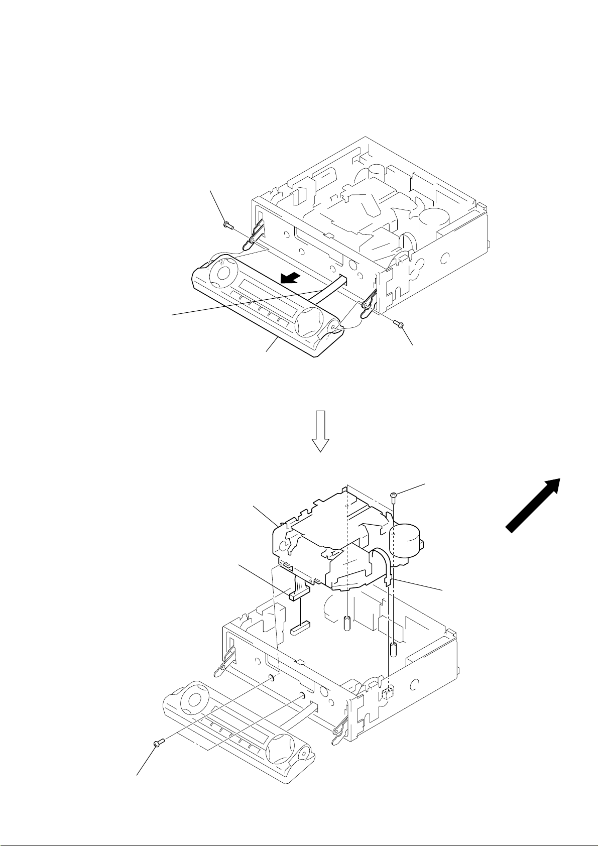
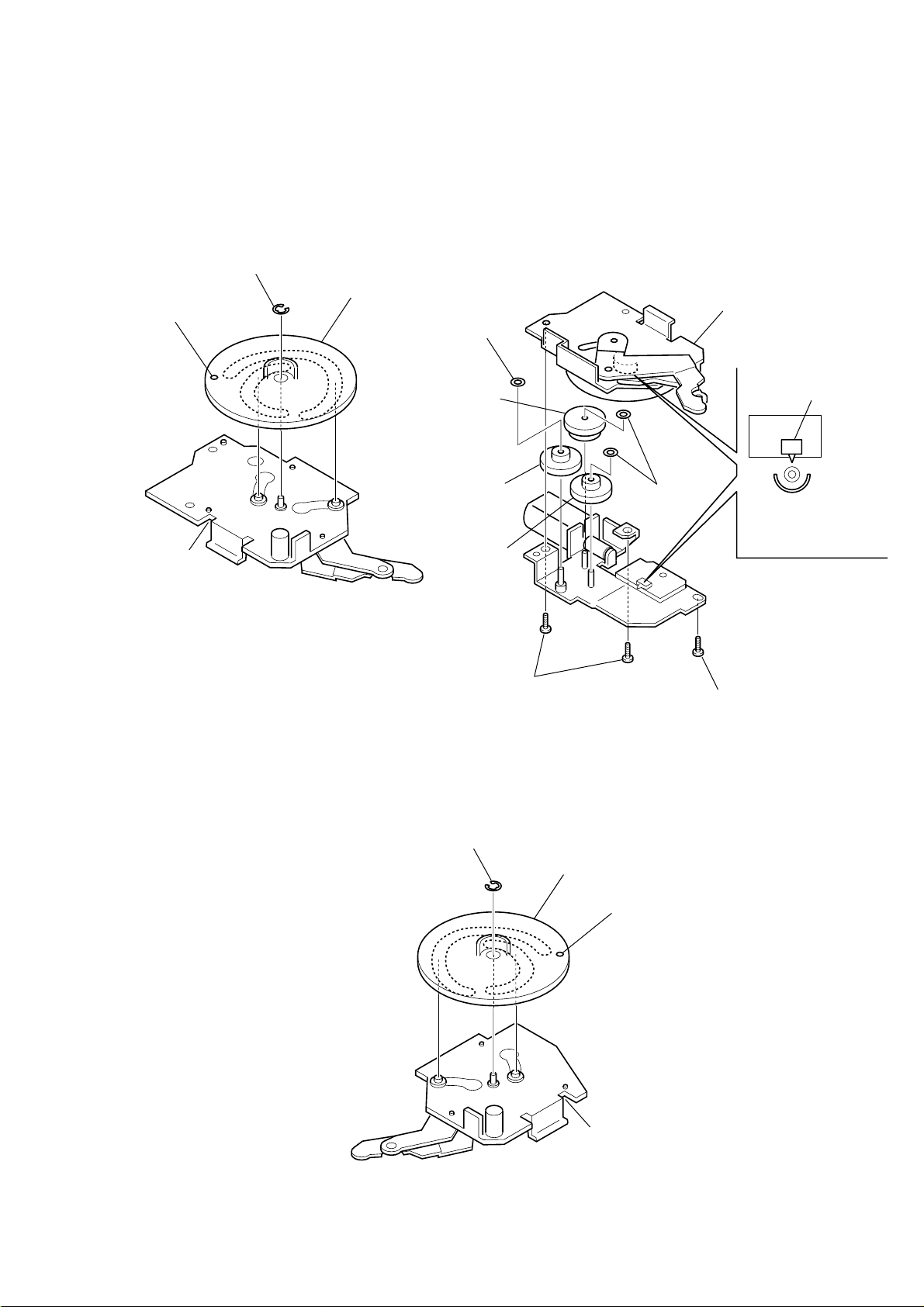
SECTION 3
DISASSEMBLY
• See page 3 for Servicing Notes.
Note: Follow the disassembly procedure in the numerical order given.
MECHANISM DECK (MG-25E-136)
1 screw
flexible board
Note: Don't pull out flexible board
from front panel ass’y.
2 front panel ass'y
1 screw
5 mechanism deck
(MG-25E-136)
3 connector
(CN400)
4 two screws
3 flexible board
(CN401)
4 two screws
(PTP2.6 × 6)
15
Page 16

FRONT PANEL ASS’Y
d
y
3 front panel ass'y
2 flexible board
(CN402)
1 cover (flexible)
• Note for Installation of Flexible Boar
2 flexible cover
1 Set the flexible board to
be at the position in the figure.
MOTOR BLOCK ASS’Y, CAM (R) ASS’Y
2 screw
(PTT2.6 × 8)
3 motor block ass'y
2 screw
(PTT2.6 × 6)
4 screw
1 connector
(CN602)
(PTT2.6 × 8)
4 screw
(PTT2.6 × 6)
5 cam (R) ass’
16
Page 17
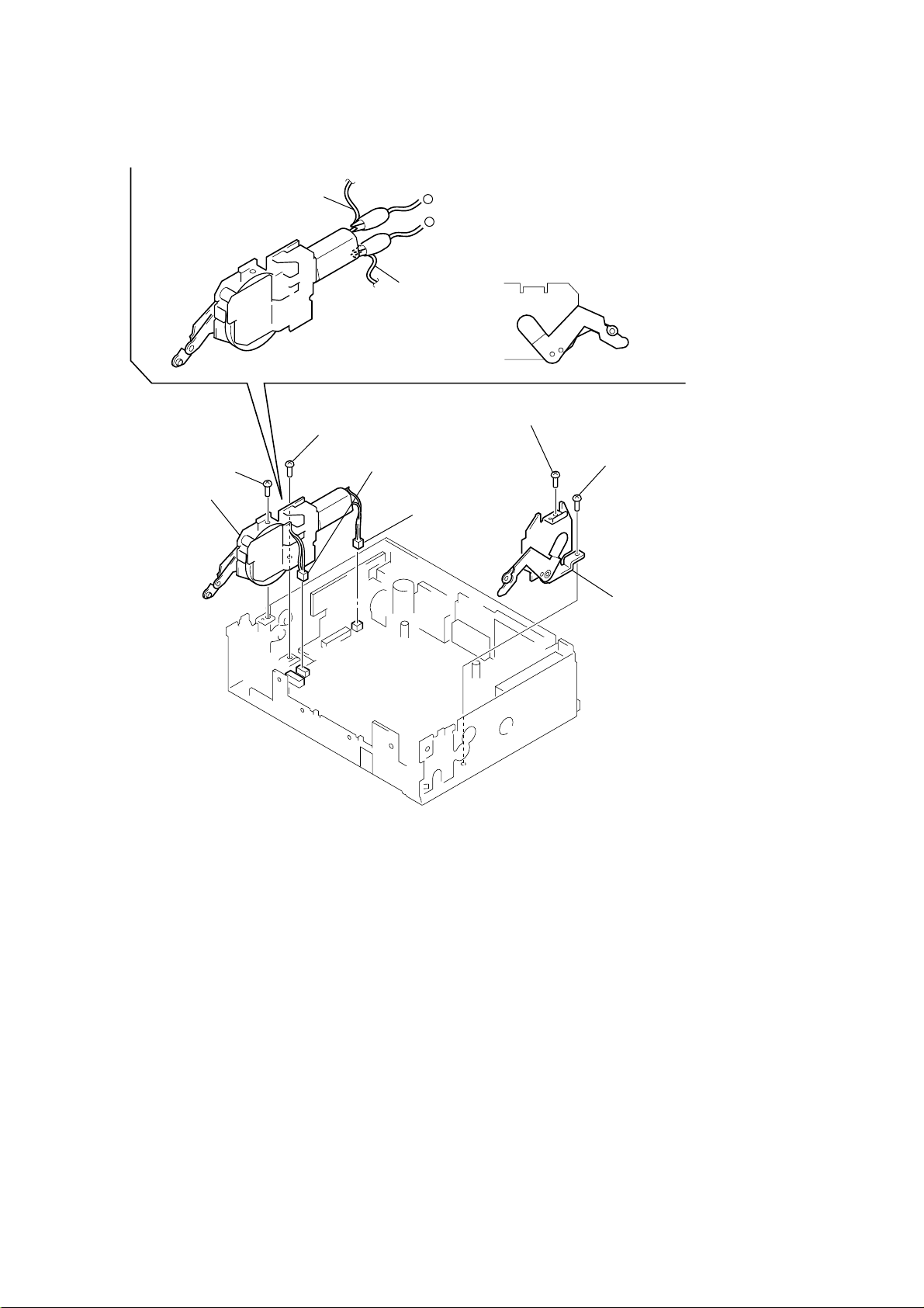
SUB PANEL (XR) SUB ASS’Y
)
2 screw
(PTT2.6 × 6)
3 sub panel (XR) sub ass'y
1 flexible board
(CN601)
2 two screws
(PTT2.6 × 6)
2 screw
(PTT2.6 × 6)
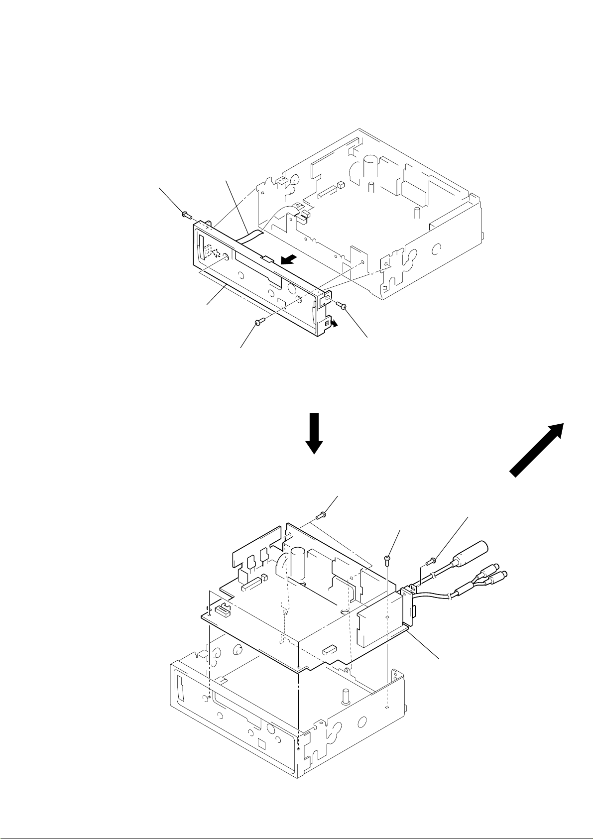
MAIN BOARD
1 two screws
(PTT2.6 × 6)
1 screw
(PTT2.6 × 6
2 three ground screws
3 main board
17
Page 18
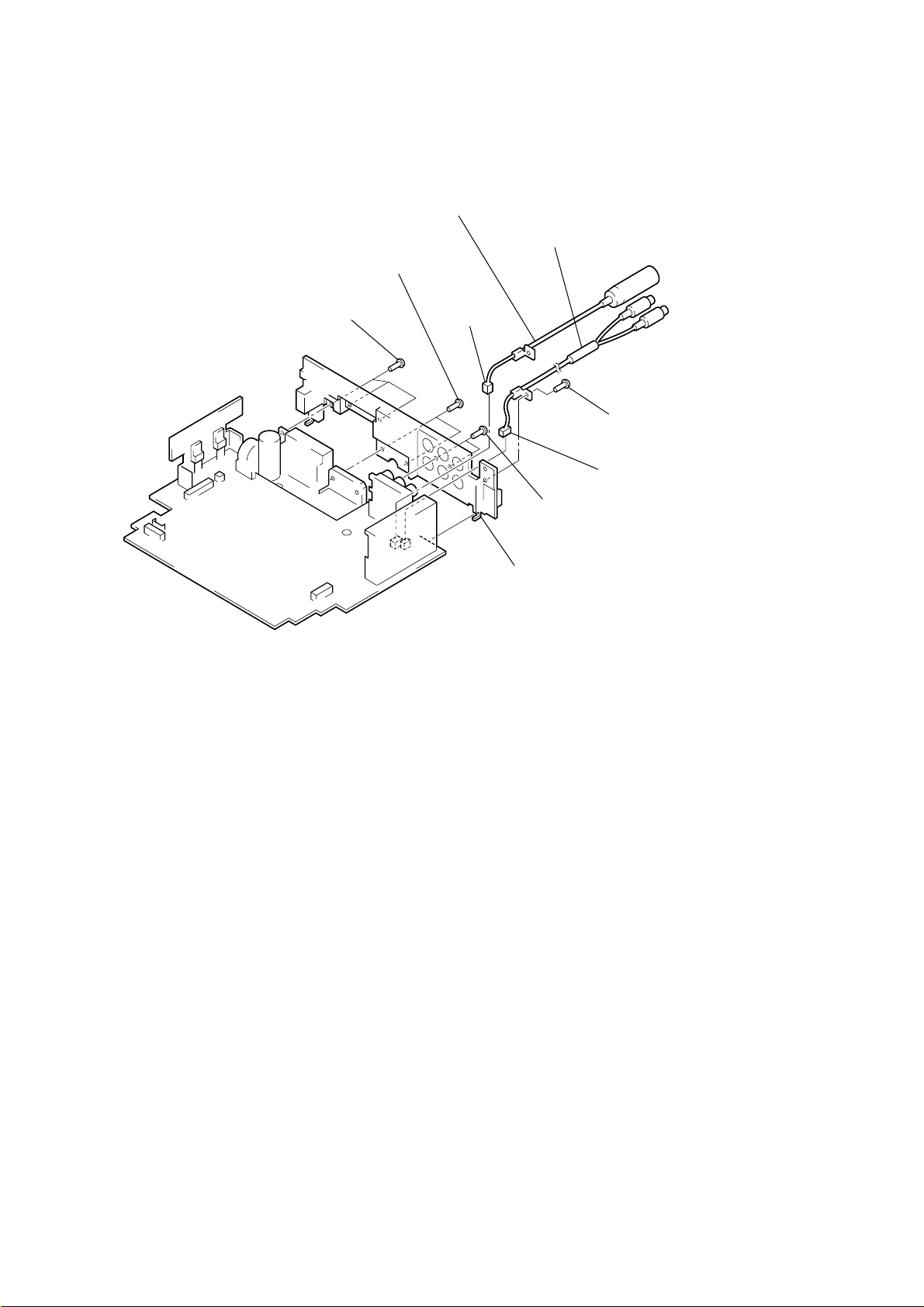
HEAT SINK
2 cord (with connector) (ANT)
6 three screws
(PTT2.6 × 8)
6 two screws
(PTT2.6 × 12)
5 cord (with connector) (SUB OUT)
1 connector
(CN100)
4 screw
(PTT2.6 × 6)
3 connector
(CN200)
6 two screws
(PTT2.6 × 8)
7 heat sink
18
Page 19
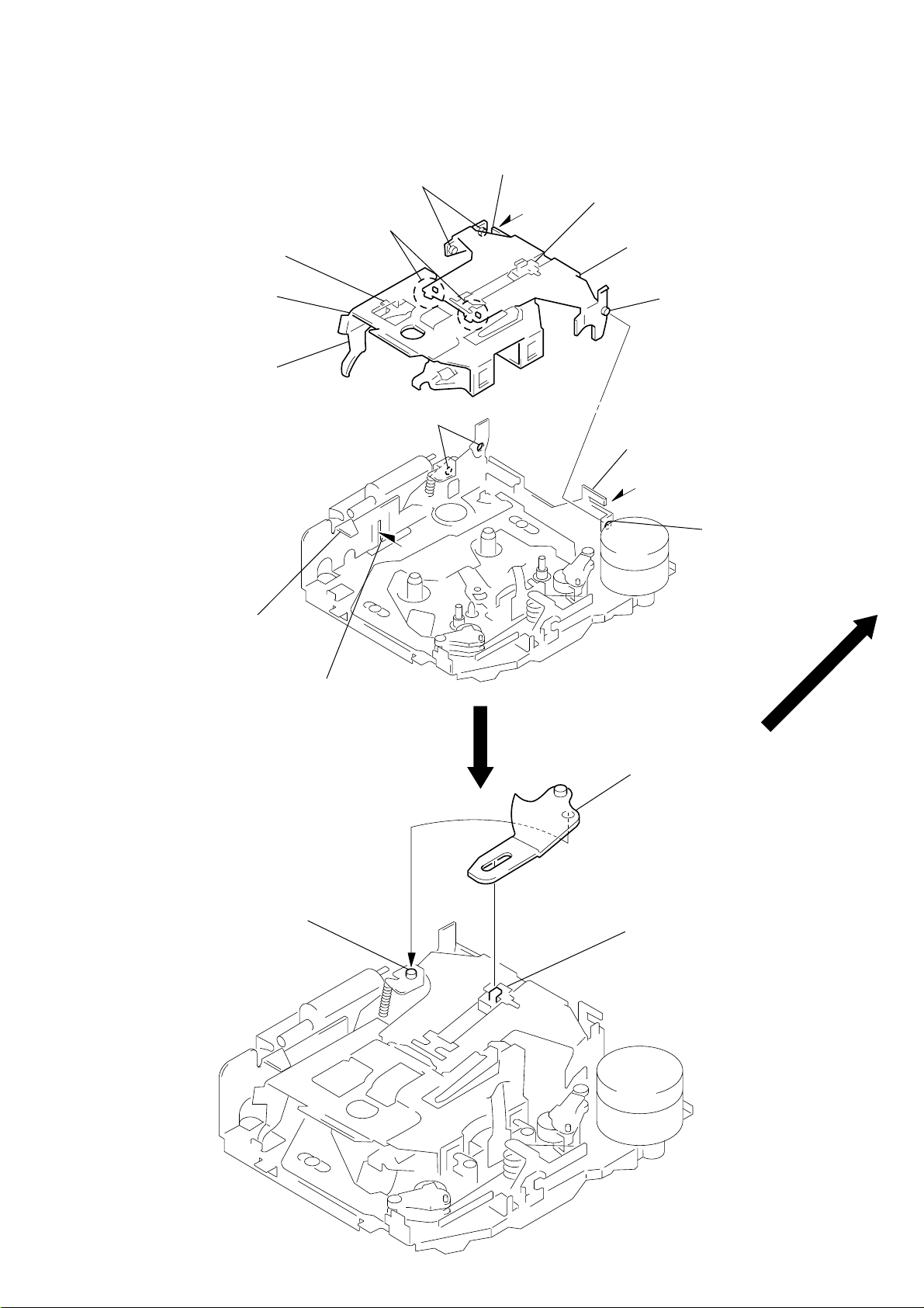
SECTION 4
Note: Follow the assembly procedure in the numerical order given.
4-1. FRONT PANEL MACHINERY
MOTOR BLOCK ASS’Y
2 stop ring
1 cam (L)
hole
6 washer (M)
ASSEMBLY
7 bracket (motor) ass'y
5 gear (C)
4 gear (B)
concave portion
Note: When installing cam (L), adjust the hole and concave portion.
3 gear (A)
8 two screws
CAM (R) ASS’Y
2 stop ring
(PTT2.6 × 6)
switch
6 washer (M)
Set bracket (motor) ass’y
to be at the position in the
figure.
8 screw
(B2.6 × 6)
1 cam (R)
hole
concave portion
Note: When installing cam (R), adjust the hole and concave portion.
19
Page 20
CAM (R) ASS’Y, MOTOR BLOCK ASS’Y
y
8 screw
(PTT2.6 × 8)
6 motor block ass'y
gray wiring
8 screw
(PTT2.6 × 6)
–
+
violet wiring
7 connector
(CN602)
7 connector
1 Supply the power to the motor.
Voltage : 9V
Violet wiring : MOTOR –
Gray wiring : MOTOR +
2 Motor stops at full open position.
full open position
4 screw
(PTT2.6 × 8)
4 screw
(PTT2.6 × 6)
(CN501)
3 cam (R) ass'
20
Page 21
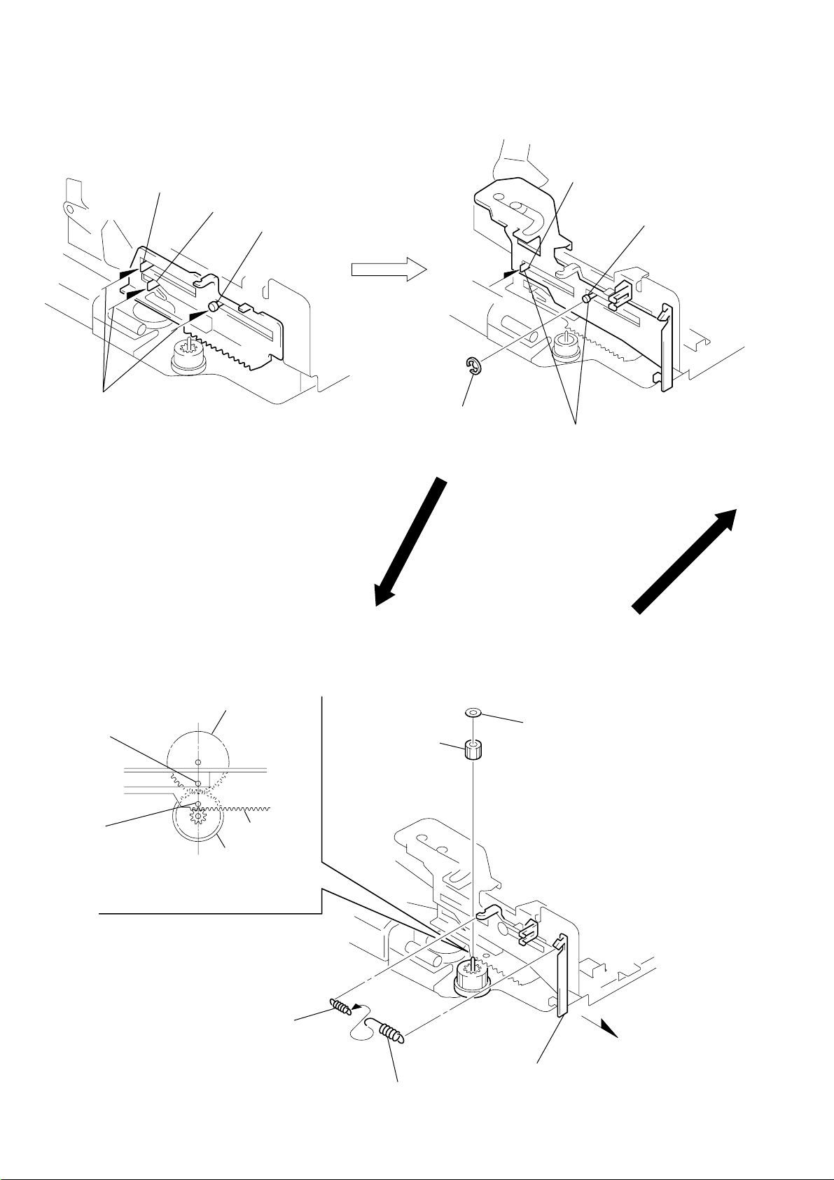
4-2. MECHANISM DECK
2 Move the arm (suction) in the arrow
direction and fit on projection.
1 Fit the arm (suction) on the shaft.
projection
HOUSING
4 Fit claw on B part.
3 Put the housing
under A part.
5 Fit projection on C part.
2 Install the hanger onto
two claws of the housing.
housing
7 Holder the hanger by bending the claw.
1 Install the catch to the hanger.
hanger
6 Fit projection on D part.
C part
8 Hold the hanger by
bending the claw.
D part
A part
B part
ARM (SUCTION)
21
Page 22
LEVER (LDG-A) / (LDG-B)
)
shaft A
1 Fit the lever (LDG-A) on
shafts A – C and install it.
shaft B
shaft C
shaft A
shaft B
3 type-E stop ring 2.0
2 Fit the lever (LDG-B) on
shafts A and B and
install it.
GEAR (LDG-FT)
hole
hole
4 Align hole in the gear (LDG-D)
gear (LDG-D)
6 polyethylene washer
5 gear (LDG-FT)
lever (LDG-A)
gear (LDG-FB)
with hole the lever (LDG-A).
1
2 tension spring (LD-2)
22
2 tension spring (LD-1)
3 Move the lever (LDG-B
in the arrow direction.
Page 23

GUIDE (C)
2 guide (C)
1 three claws
MOUNTING POSITION OF CAPSTAN/REEL MOTOR (M901)
two precision screws
(P2 × 2)
capstan/reel motor
(M901)
30˚
23
Page 24
SECTION 5
j
)
r
MECHANICAL ADJUSTMENTS
SECTION 6
ELECTRICAL ADJUSTMENTS
1. Clean the following parts with a denatured-alcohol-moistened
swab:
playback head pinch roller
rubber belt capstan
idler
2. Demagnetize the playback head with a head demagnetizer.
3. Do not use a magnetized screwdriver for the adjustments.
4. The adjustments should be performed with the power supply
voltage (14.4 V) unless otherwise noted.
• Tor que Measurement
Mode Torque Meter Meter Reading
Forward CQ-102C 30 – 65 g•cm
Forward
Back Tension
Reverse CQ-102RC (25 – 55 g•cm)
Reverse
Back Tension
FF, REW CQ-201B 60 – 200 g•cm)
CQ-102C 0.5 – 4.5 g•cm
CQ-102RC 0.5 – 4.5 g•cm
2.95 – 6.73 mN•m
(0.42 – 0.90 oz•inch)
0.05 – 0.44mN•m
(0.01 – 0.06 oz•inch)
2.95 – 6.73 mN•m
(0.42 – 0.90 oz•inch)
0.05 – 0.44mN•m
(0.01 – 0.06 oz•inch)
5.89 – 19.61 mN•m
(0.83 – 2.78 oz•inch)
TEST MODE
<Set the Test Mode>
1. Turn ON the regulated power supply. (All LEDs on the set
lights up, and the clock is displayed.)
Note: Press the [OFF] button, if the clock is not displayed.
2. Push the preset [4] button.
3. Push the preset
4. Press the preset
[5] button.
[1] button for more than two seconds.
5. Then the display indicates all lights, the test mode is set.
<Release the Test mode>
1. Push the [OFF] button.
See the adjustment location from on page 25 for the
adjustment.
TAPE DECK SECTION
0 dB=0.775 V
Tape Speed Adjustment
Setting:
speed checker
or
test tape
WS-48A
(3 kHz, 0 dB)
frequency counte
10 kΩ
• Tape T ension Measurement
Mode Tension Meter Meter Reading
Forward CQ-403A
Reverse CQ-403R
more than 90 g
(more than 3.18 oz)
more than 90 g
(more than 3.18 oz)
set
AUDIO OUT REAR
ack (CN300
+–
Procedure:
1. Put the set into the FWD PB mode.
2. Adjust adjustment resistor for inside capstan motor so that the
reading on the speed checker or frequency counter becomes in
specification.
Specification: Constant speed
Speed checker Frequency counter
–1.5 to +2.5% 2,955 to 3,075 Hz
Adjustment Location: See page 25.
24
Page 25

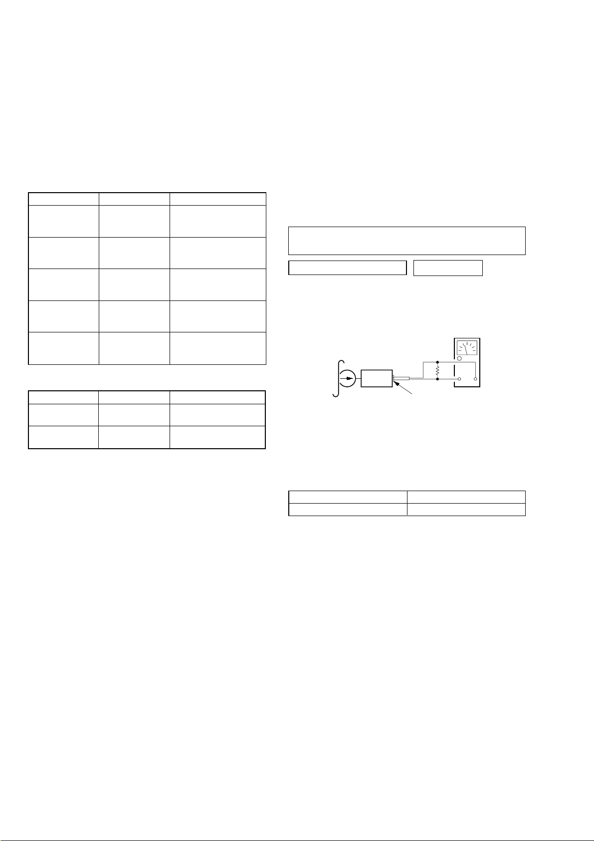
Dolby Level Adjustment
r
)
Setting:
[SOURCE] button : ON
[MENU] (PLAY MODE) and
Preset
–
[DISC ] buttons : NR off
[SOUND] (BAS) button : Center
[SOUND] (TRE) button : Center
[SOUND] (BAL) button : Center
[SOUND] (FAD) button : Center
[+] (VOL) button : Maximum
Adjustment Location:
– SET UPPER VIEW –
TUX100
test tape
P-4-D400
(400Hz, 0 dB)
MAIN board
TP (DOLBY-L)/
TP (DOLBY-R)
set
level mete
+
–
Procedure:
1. Put the set into the FWD PB mode.
2. Adjust RV400 (L-CH) and RV401 (R-CH) so that the level
meter reading is –6±0.5 dB (0.37 to 0.41 V).
TUNER SECTION
Tuner section adjustments are done automatically in this set.
Tape Speed
Adjustment
RV401
Dolby Level
Adjutment (R-ch
RV400
Dolby Level
Adjutment (L-ch)
– SET BOTTOM VIEW –
TP (DOLBY-R)
TP (DOLBY-L)
Dolby Level
Adjustment
25
Page 26

MEMO
26
Page 27

SECTION 7
DIAGRAMS
XR-M500R/M550
7-1. BLOCK DIAGRAM – TUNER/TAPE Section –
FM/AM TUNER UNIT
TUX100
(FM/AM ANTENNA)
HP901
(PLAYBACK)
FWD
L-CH
FWD
R-CH
REV
L-CH
REV
R-CH
R-CH
R-CH
FM-ANT
2
AM-ANT
1
TAPE EQUALIZER AMP,
DOLBY NR AMP, AMS
PBF
IN1
34
32
PBR
IN1
DRSW
19
IC401
R-CH
EQ AMP
TAPESW
18
DOLBY LEVEL (L)
PB
OUT1
29 27
R-CH
RV400
R-CH
TAPE
IN1
+
MUTE
SWITCH
Q404
MUTE
INSW
17
R-CH
DOLBY
NR AMP
DOLBY
16
11
D101
BU 5V
R-CH
AMS
DET
MSSW
20
BACKUP +5V
TUNER VCC
TUNER +5V
16
5
VCC
LINE
OUT1
MS
OUT
VDD
MPX
10
MUTING
Q101
AM-DET
E2P-SIO
E2P-CKO
FM AGC
17
18
4
24
14
S-METER
14
RDSDET
9
(XR-M500R)
SDA
SCL
AM-IF
12 13
16
MPX
LVIN
20
DATA
CLOCK
57 kHz
BAND-PASS
FILTER
MULTI
PATH
DETECTOR
19
SC
OUT
18
MPTH
2
8
RDS DECODER
IC700
CIN
19
COMPARATOR
OSCILLATOR
CLOCKED
& CLOCK
OSCI
5
X700
4.332MHz
OSCO
4
SIGNAL
QUALITY
DECODER
RDS/RDBS
DEMODULATOR
& DECODER
DAVN
8
5
4
INTERFACE
REGISTER
MUTING
Q102
D102
IIC BUS
SLAVE
TRANSCEIVER
MUTING CONTROL
SWITCH
Q105
SCL
10
SDA
9
CLOCK
DATA
BUFFER
Q750
BAND-PASS
FILTER
IC750
NOISE DET
DISCHARGE
SWITCH
Q751
MPX
AM
AM-IF
TAPE L
DATA,CLOCK
A
B
C
D
E
(Page 28)
(Page 28)
(Page 28)
(Page 28)
(Page 28)
M901
(CAPSTAN/REEL)
05
LEVEL
51
FM AGC
E2P-CKO
LM-EJ
REGULATOR
REGULATOR
CONTROL SWITCH
53
VSM
SYSTEM CONTROLLER
Q400
Q401
IC601 (1/4)
TAPEON
59
BATT B+
1
MOTOR
DRIVE
IC400
VCC
2
AMSIN
IN1
IN2
10
11
E2P-SIO
LM-LOD
60
61
3
4
3
23
7
N-ROUT
M
MTLOUT
CAPSTAN/REEL
MOTOR DRIVE
Q402
BATT B+
Q403
CM-ON
62
LOADING/TAPE
OPERATION
REEL SENSOR B+
120
DOLBY
AMSON
OUT1
9
M
OUT2
7
LOADING/TAPE OPERATION
MOTOR DRIVE
52
MPTH
POS0 – POS3
TAPE OPERATION
SWITCH
EJECT/FF/REW/
REV/FWD MODE DETECT
75
DAVN
TAKE-UP
REEL
SENSOR
TAPE
DETECT
REEL SENSOR BOARD
5764 – 67
BUFFER
REEL
SUPPLY
SENSOR
REEL
50
QUALITY
56
NS MASK
32
TUNATT
• SIGNAL PATH
: FM
: AM (MW/LW)
: TAPE PLAY
G
(Page 28)
2727
Page 28

XR-M500R/M550
7-2. BLOCK DIAGRAM – MAIN Section –
CN300 (1/2)
BUS
AUDIO IN
L
(Page 27)
(Page 27)
(Page 27)
(Page 27)
R
B
D
C
A
AM
TAPE L
AM-IF
MPX
R-CH
1
11
4
12
13
INPUT SELECT, FM MPX,
ELECTRICAL VOLUME
IC100
SEL
AM
FD1L–
AMIF
MPX
AM/FM NOISE
L.P.F
DIGITAL
CONTROL
IIC BUS
SCL
SDA
20 21
INPUT
MULTIPLEXER
BLANKER
LOUDNESS
VOLUME
MUTE
PILOT
CANCELATION
PILOT DET
PLL
QUAL
QUALITY
17
SOFT
MUTE
SM
18
TONE
CONTROL
LOUDNESS
DEMODULATOR
STEREO ADJUST
STEREO BLEND
OUTPUT
L.P.F.
D/A
CONVERTER
MPIN
LEVEL
1514
SUBWOOFER
SELECTOR
+PHASE CONTROL
HIGH-
S & H
CUT
MONO
FADER
R-CH
MIXER
MONO
FADER
OUTSSL
OUTSSR
OUT LF
OUT LR
OUTSWL
OUTSWR
• SIGNAL PATH
: FM
: AM (MW/LW)
: TAPE PLAY
: BUS AUDIO IN
SPEANA
(XR-M500R)
24
23
30
29
26
25
(XR-M550)
(XR-M500R)
LINE DRIVER
IC200
LINE DRIVER
IC200
R-CH
R-CH
R-CH
D203
D204
D200
MUTING
Q250
MUTING
Q251
MUTING
Q200
MUTING
Q201
MUTING
Q204
MUTING
Q254
CN300 (2/2)
CN200
H
L
R
L
R
(L)
(R)
(Page 29)
AUDIO OUT
FRONT
AUDIO OUT
REAR
(XR-M550)
SUB OUT
(MONO)
(Page 27)
(Page 27)
G
E
LEVEL
DATA, CLOCK
POWER AMP
IC300
5
22
SWITCH
Q222
MUTE
OUT2+
3
OUT2–
21
OUT4+
23
OUT4–
9
OUT1+
OUT1–
7
17
OUT3+
19
OUT3–
STBY
4
AMP ON
MUTING
CONTROL SWITCH
Q220, 221
IN2
12
IN4
14
DATA
CLOCK
70
IIC-SCL
IIC-SDA
SYSTEM CONTROLLER
05
3171
IC601 (2/4)
VOL ATT
TESTIN
TEL-MUTE
ST-BY
MUTE
84
16
55
D205
BATT
B+
5
BATTERY OFF
MUTE DRIVER
Q223
LEVEL SHIFT
Q603
D206
11
IN1
15
IN3
AMP MUTING
CN301 (1/2)
(POWER CONNECTOR)
MUTE
D201
1
9
4
12
2
10
3
11
15
13
I
J
BATT
B+
FL+
FL–
FR+
FR–
RL+
RL–
RR+
RR–
TEST
TEL-ATT
(Page 30)
(Page 29)
2828
Page 29

XR-M500R/M550
7-3. BLOCK DIAGRAM –DISPLAY/BUS CONTROL Section –
ILL ON
K
(Page 30)
SPEANA
H
(Page 28)
MUTE
J
(Page 28)
BACK UP +5V
BACK UP +5V
FRONT PANEL
OPEN/CLOSE MOTOR DRIVE
M
M601
FRONT PANEL
OPEN/CLOSE
05
IC502
3
14
SPECTRUM
ANALYZER BUFFER
D103
RESET SIGNAL
GENERATOR
IC602
OUT1
MOTOR
OUT2
DRIVE
IC101
RAM RESET
45
VCC
M BATT
IC603
12
VREF
OPEN
CLOSE
RNF
MUTING
Q611
S901
(RESET)
S902
RESET
REGULATOR
IC503
REFERENCE
VOLTAGE SWITCH
Q501, 502
11
6
16
SPECTRUM ANALYZER BAND-PASS FILTER
AIN
8
90
86
85
+9V
MOTOR OVER LOAD
DETECT
IC500, Q500
RESET
HSTX
RAMBU
BATT B+
B.P.F.
f: 6.8Hz
to
14.4kHz
D509
IC102
D628
FP CTRL
40
PEAK
HOLD
REGISTER
6
SYSRST
MOT+
MOT–
98 97
DECODER
SCHMITT TRIGGER
I-DET
96
MULTI
PLEXER
X0
X601
3.68MHz
IC606
AOUT
17
A
10
B
11
C
12
SEL
14
X602
18.432MHz
X1
X0A
X600
32.768kHz
LIQUID CRYSTAL DISPLAY
DRIVE CONTROLLER
52
ILL-ON
SPE-IN
105
SPE-A
40
SPE-B
41
SPE-C
42
SPE-SEL
43
EXTAL
86
XTAL
85
RES
81
BOOT
57
106
BOOT
BEEP
X1A
1592 93 74 73
BUZZER DRIVE
Q604
BZ600
(BUZZER)
IC607
LCD-INH
LCD-SCK
LCD-CE0
LCD-CE1
TX/LCD-DATA
RX
LINK-OFF
UNISO
UNISI
UNISCK
BUS-ON
BU-IN
NMI
LED SW1
LED SW2
SP-LAT
46
47
33
115
116
4
SPELAT
LED SW1
LED SW2
SYSTEM CONTROLLER
IC601 (3/4)
PACK SW
111
S901
CASSETTE
IN/OUT DETECT
(XR-M500R)
LSW901 – 919,
LSW921 – 925,
S901, 902
(XR-M550)
LSW902, 904 – 918,
LSW921 – 925,
S901, 902
LIQUID CRYSTAL DISPLAY DRIVER
69
64
66
70
60
62
50
LEVEL SHIFT
97
98
101
38
49
82
D611
Q503
DATA
BUS-ON
BU IN
KEY IN047KEY IN1
46
CLK
D627
12TX13
RX
RC IN1
RC IN079KEY ACK
72
48
D501
KEY ACTIVE
SWITCH
Q600, 601
J500
REMOTE IN
97
99
98
100
LIQUID CRYSTAL DISPLAY DRIVER
97
99
98
100
BACK UP +5V
LCD-INH
LCD-CLK
LCD-CE0
LCD-DATA
LCD-INH
LCD-CLK
LCD-CE1
LCD-DATA
IC901
OSC
96
OSC
C906, R972
IC902
OSC
96
OSC
C911, R982
80
DIMMER
VLCD
VLCD
LCD-SW2
LCD-SW1
AD ON
86
85
1 – 71
SEG1 – SEG71
83 – 76
COM1 – COM8
1 – 69
SEG1 – SEG69
83 – 76
COM1 – COM8
85
84
85
UNISO
UNISI
UNICKO
BUS-ON
BU-IN
SIRCS
LED DRIVE
Q905, 906
LIQUID CRYSTAL
DISPLAY
(OPERATION SIDE)
LCD902
LIQUID CRYSTAL
DISPLAY
(SECURITY SIDE)
LCD901
18
17
19
14
77
24
DATA
CLK
BUS-ON
BU IN
LED903 – 908,
LED911 – 916
(LCD BACK LIGHT)
SONY BUS INTERFACE
RESET
13
DATA
IN
9
DATA
OUT
8
CLK
IN
11
BUS
ON
12
BU IN
10
BATTERY CHECK
SIRCS BUFFER
REMOTE CONTROL
IC900 (SUB Board)
REMOTE CONTROL
IC903 (DISPLAY Board)
REGULATOR
D909
REGULATOR
CONTROL SWITCH
Q910
IC501
RST
RESET
SWITCH
DATA
CLK
BUS
BUS ON
SWITCH
BATTERY
CHECK
ON
BATT
Q504
Q506
RECEIVER
RECEIVER
2
6
4
1
3
D508
D505
D502
LCD +9V
LSW-SW1, LSW-SW2
BATT B+
D513
BUS ON/OFF
SWITCH
Q505
BATT B+
BATT B+
(Page 30)
TH601
7
BATT
2
RESET
5
DATA
4
CLK
6
BUS ON
3
SIRCS
CN500
BUS CONTROL IN
(FOR SONY BUS)
L
2929
Page 30

XR-M500R/M550
7-4. BLOCK DIAGRAM – POWER SUPPLY Section –
SYSTEM CONTROLLER
IC601 (4/4)
ACC IN ACC
ILL IN
CLOSE SW
OPEN SW
TU-ON
FLS-PWON
PW ON
CN301 (2/2)
81
95
99
100
114
82
83
D904
CASSETTE SLOT
INDICATOR
D905
Z
FRONT PANEL
OPEN/CLOSE DETECT
CLOSE
OPEN
D609
B+ SWITCH
Q900, 901
TUNER VCC
TUNER +5V
TUNER CIRCUIT/
RDS DECODER (IC701)
B+ (XR-M500R)
B+
SPECTRUM ANALYZER
CONTROL (IC102)
B+
+5V REGULATOR
Q100
+5V REGULATOR
Q106, 107
B+ SWITCH
Q103, 104
RIPPLE FILTER
IC604
+9V REGULATOR
IC605
BATT B+
ACCESSORY
CHECK
Q608
ILLUMINATION
LINE DETECT
Q607
ANTENNA
REMOTE SWITCH
Q300, 301
AMP
REMOTE SWITCH
Q302, 303
D318 D315
TH301
TH300
D316
D308
D309
(POWER CONNECTOR)
7
14
ILL
16
B+
6
ANT-R
5
AMP-R
(Page 29)
BACK UP +5V
ILL ON
K
05
(XR-M500R)
LED917 – 921, LSW901 – 911,
LSW913 – 919, 921 – 925
(FOR ILLUMINATION)
(XR-M550)
LED917 – 921, LSW902, 904 – 911,
LSW913 – 918, 921 – 925
(FOR ILLUMINATION)
LED901
(ILLUMINATION)
LSW912
Z
+6V REGULATOR
IC604
LCD +9V
LCD DRIVER
(IC901, 902)
B+
B+ SWITCH
Q903, 904
B+ SWITCH
Q901, 902
LCD-SW1
LCD-SW2
AMP ON
LCD-SW1, LCD-SW2
I
L
(Page 28)
(Page 29)
3030
Page 31

XR-M500R/M550
7-5. NOTE FOR PRINTED WIRING BOARDS AND SCHEMATIC DIAGRAMS
Note on Printed Wiring Board:
• X : parts extracted from the component side.
• Y : parts extracted from the conductor side.
• b : Pattern from the side which enables seeing.
(The other layers' patterns are not indicated.)
Caution:
Pattern face side: Parts on the pattern face side seen from
(Conductor Side) the pattern face are indicated.
Parts face side: Parts on the parts face side seen from
(Component Side) the parts face are indicated.
Note on Schematic Diagram:
• All capacitors are in µF unless otherwise noted. pF: µµF
50 WV or less are not indicated except for electrolytics
and tantalums.
• All resistors are in Ω and 1/
specified.
f
•
• C : panel designation.
• U : B+ Line.
• H : adjustment for repair.
• Power v oltage is dc 14.4V and fed with regulated dc power
• Voltages and waveforms are dc with respect to ground
• Voltages are tak en with a V OM (Input impedance 10 MΩ).
• Waveforms are taken with a oscilloscope.
• Circled numbers refer to waveforms.
• Signal path.
• Please refer to servicing notes (page 3) for system of
: internal component.
supply from ACC and BATT cords.
under no-signal (detuned) conditions.
no mark : FM
( ) : AM (MW)
[]: LW
〈〈 〉〉 : T APE PLA YBA CK
Voltage variations may be noted due to normal production tolerances.
Voltage variations may be noted due to normal production tolerances.
F : FM
f : AM (MW/LW)
L : BUS AUDIO IN
E : TAPE PLA Y
TYPE A, B, C and D.
4
W or less unless otherwise
• Waveforms
– MAIN Board –
1 IC701 5 OSCI
232 ns
2 IC601 ud XIA
306
µ
s
3 IC601 od X1
2.4 Vp-p
3.1 Vp-p
– DISPLAY Board –
1 IC901 y; OSC
22.8 µs
2 IC902 y; OSC
µ
s
22.8
3.2 Vp-p
3.2 Vp-p
272 ns
4 IC607 ih EXTAL
54 ns
5.5 Vp-p
3 Vp-p
3131
Page 32

XR-M500R/M550
• Semiconductor Location
Ref. No. LocationRef. No. Location
D100 D-13
D101 C-13
D102 G-8
D103 I-9
D104 D-13
D200 B-9
D201 I-5
D202 H-6
D203 B-9
D204 A-9
D300 C-7
D301 B-7
D302 B-6
D303 C-7
D304 B-8
D305 C-8
D306 B-8
D307 C-8
D310 B-3
D311 C-4
D312 E-3
D315 B-5
D316 B-6
D318 B-5
D400 F-3
D500 F-4
D501 B-2
D502 I-4
D505 F-4
D506 G-4
D507 G-4
D508 G-4
D509 H-2
D511 H-4
D512 H-4
D513 G-4
D604 D-2
D606 H-5
D607 D-2
D610 J-3
D611 J-6
D627 J-9
D628 I-5
D701 F-8
D750 F-13
IC100 F-11
IC101 G-9
IC102 J-6
IC202 C-11
IC400 F-3
IC401 H-11
IC501 H-4
IC502 G-2
IC503 H-3
IC601 F-6
IC602 E-5
IC603 D-5
IC606 J-7
IC607 I-8
IC700 J-12
IC750 F-14
Q100 E-13
Q101 D-12
Q102 E-12
Q103 E-8
Q104 F-8
Q105 H-8
Q106 K-6
Q107 K-6
Q200 B-11
Q201 B-11
Q204 C-12
Q220 I-6
Q221 H-6
Q222 I-6
Q250 B-10
Q251 B-10
Q254 C-12
Q300 E-4
Q302 E-4
Q401 G-3
Q402 E-3
Q403 F-3
Q404 H-11
Q500 I-3
Q501 I-2
Q502 I-2
Q503 F-4
Q504 F-4
Q505 G-5
Q506 I-4
Q600 D-6
Q601 D-6
Q602 G-8
Q603 G-7
Q604 J-3
Q605 F-9
Q606 E-9
Q607 D-4
Q608 D-4
Q611 I-10
Q750 F-13
Q751 G-14
7-6. PRINTED WIRING BOARD – MAIN Board (Component Side) –
(Page 40)
3232
Page 33

7-7. PRINTED WIRING BOARD – MAIN Board (Conductor Side) –
XR-M500R/M550
TO
CN301
ANT REM
GRN
WHT
WHT
GRN
ATT
AMP REM
(M500R)
(M550)
RL+ RL–
GRN/BLK
FL+ FL–
FR+ FR–
RR+ RR–
1 9
2 10
3 11
4 12
5 13
6 14
7 15
8 16
ACC GND
NC BATT
NC NC
WHT/BLK
GRY/BLK
VIO/BLK
WHT/BLK
GRN/BLK
VIO/BLK
GRY/BLK
LIGHT BLU
BLU/WHT
ORG/WHT
YEL
BLK
ILL
ORG/WHT
YEL
GRY
VIO
VIO
GRY
BLU
RED
BLK
RED
BLU
(Page 38)
WHT/BLK
1 9
2 10
3 11
4 12
5 13
6 14
7 15
8 16
WHT
GRN/BLK
GRN
VIO/BLK
VIO
GRY/BLK
GRY
LIGHT BLU
BLU/WHT
ORG/WHT
BLU
RED
YEL
BLK
FRONT LCH (–)
FRONT LCH (+)
REAR LCH (–)
REAR LCH (+)
REAR RCH (–)
REAR RCH (+)
FRONT RCH (–)
FRONT RCH (+)
ATT
AMP REM
ILL IN
ANT REM
ACC
BATT
GND
• Semiconductor Location
Ref. No. Location
D308 D-4
D309 D-4
D317 C-2
D320 A-6
D401 D-2
D503 B-3
D504 B-3
D510 I-3
D515 G-2
D516 G-2
D601 F-5
D602 F-5
D603 F-5
D608 F-4
D609 E-5
D612 J-2
D613 J-2
D617 K-9
D618 K-9
Ref. No. Location
D619 J-9
D620 J-9
D621 K-9
D623 J-9
D624 J-10
D625 K-10
D626 J-9
IC200 D-10
IC201 D-11
IC300 A-8
IC500 H-3
IC604 C-1
IC605 D-1
Q301 E-3
Q303 E-3
Q400 G-3
3333
Page 34

XR-M500R/M550
7-8. SCHEMATIC DIAGRAM – MAIN Board (1/4) – • See page 31 for Waveforms. • See page 42 for IC Block Diagrams.
(Page
35)
(Page 37)
(Page 36)
3434
Page 35

7-9. SCHEMATIC DIAGRAM – MAIN Board (2/4) – • See page 42 for IC Block Diagrams.
XR-M500R/M550
(Page 34)
(Page 36)
(Page 37)
3535
Page 36

XR-M500R/M550
7-10. SCHEMATIC DIAGRAM – MAIN Board (3/4) – • See page 31 for Waveforms. • See page 42 for IC Block Diagrams.
(Page 34)
(Page 35)
(Page
37)
3636
Page 37

7-11. SCHEMATIC DIAGRAM – MAIN Board (4/4) – • See page 31 for Waveforms.
(Page 34)
XR-M500R/M550
Ver 1.1
(Page 35)
(Page
36)
(Page 41)
(Page 39)
3737
Page 38

XR-M500R/M550
7-12. PRINTED WIRING BOARD – SUB Board –
• Semiconductor
Location
Ref. No. Location
D900 B-1
D901 A-1
D902 A-2
D903 A-1
D904 A-9
D905 A-10
IC900 A-11
• Semiconductor
Location
Ref. No. Location
D907 A-9
D908 A-10
Q900 B-12
Q901 A-12
(Page 33)
FOR TEST
3838
Page 39

7-13. SCHEMATIC DIAGRAM – SUB Board –
XR-M500R/M550
(Page 37)
3939
Page 40

XR-M500R/M550
• Semiconductor
Location
Ref. No. Location
LED901 A-1
LED903 B-2
LED904 A-2
LED907 B-2
LED908 B-2
LED911 B-13
LED912 B-13
LED913 C-2
LED914 C-13
LED915 B-13
LED916 A-13
IC901 B-7
IC902 B-8
IC903 C-2
Q901 B-2
Q902 B-2
7-14. PRINTED WIRING BOARD – DISPLAY Board –
• Semiconductor
Location
Ref. No. Location
D902 B-12
D903 C-11
D904 C-11
D905 C-10
D906 C-11
D907 B-11
D908 C-11
D909 C-12
LED905 B-10
LED906 B-10
LED917 B-3
LED918 C-3
LED919 B-2
LED920 C-2
LED921 A-2
Q903 B-3
Q904 C-4
Q905 C-4
Q906 C-3
Q910 C-12
(Page 32)
4040
Page 41

7-15. SCHEMATIC DIAGRAM – DISPLAY Board – • See page 31 for Waveforms.
(Page
37)
XR-M500R/M550
4141
Page 42

• IC Block Diagrams
– MAIN Board –
IC100 TDA7402TR
IC102 BA3834F
ACINLF
SWINR
SWINL
ACOUTR
ACOUTL
CREF
MUX
MD1
MD1G
MD2
MD2G
34
35
36
37
38
39
LP
HP
BASS
TREBLE
VOLUME
SOFTMUTE
LOUDNESS
40
+
IN-GAIN
+AUTO ZERO
MAIN SOURCE
SELECTOR
41
MAIN
42
43
PHONO
44
MAIN CH0 AUX
1 2 3 4 5 6 7 8 9 10 11
SEL
SER
ACINLR
ACINRF
ACINRR
33 32 31 30 29 28 27 26 25
LOUDNESS
IN-GAIN
MUTE
SELECTOR
FD2L–
FD2R+
FRONT
FD2R–
REAR
SW
FM
AM
AM
VOICE
BANDPASS
COMPANDER
MIXING
SELECTOR
MULTIPLEXER
FD1L+
FD1L–
ACIN
MAIN
INPUT
FD1R+
SECOND
FD1R–
OUTPUT
SELECTOR
SECOND SOURCE
FD2L+
MONO-
FADER
DIGITAL CONTROL IIC-BUS
OUTLF
MONO-
FADER
OUTLR
MIXER
MONOFADER
BEEP
AM/FM
NOISE BLANKER
OUTRF
OUTRR
MONOFADER
HIGH-CUT
S&H
25kHz
LP
DEMODULATOR
+STEREO ADJUST
+STEREO BLAND
PILOT
CANCELATION
OUTSWL
MONOFADER
SUBWOOFER
+PHASE
CONTROL
PIL DET
PLL
MONO-
FADER
OUTSWR
SUPPLY
PULSE
FORMER
QUAL
MULTIPATH
DETECTOR
D/A
CONVERTER
80kHz
LP
OUTSSL
24 23
OUTSSR
22
21
20
19
18
17
16
15
14
13
12
VDD
SCL
SDA
GND
SM
QUAL
MPOUT
MPIN
LEVEL
MPX
AMIF
AOUT
1718
MULTIPLEXER DECODER
REGISTER
PEAK
HOLD
1kHz
B.P.F.
DIFFERENTIAL
AMPLIFIER
6
N.C.
PEAK
HOLD
2.4kHz
B.P.F.
7
CIN
16
PEAK
HOLD
68Hz
B.P.F.
REGISTER
1
PEAK
HOLD
170Hz
B.P.F.
BIASC
2
VREFC
REGISTER
4
3
N.C.
RREF
GND
PEAK
HOLD
420Hz
B.P.F.
5
REGISTER
DIFOUT
IC200, 201 NJM2160AM-TE2 (XR-M550)
1
VCCL
2
INL
SVRL
INML
INMR
SVRR
INR
BUFFER
3
BUFFER
REFERENCE
4
5
REFERENCE
6
7
BUFFER
BUFFER
VCCL
VCCL
VCCR
VCCR
LIFT
AMP
SIGNAL
AMP
SIGNAL
AMP
LIFT
AMP
TEST
REGISTER
8
AIN
CL+
16
CL–
15
LGND
14
OUTL
13
12
OUTR
RGND
11
CR–
10
9
CR+
N.C.
SEL
N.C.CB
A
12
14
13
10
REGISTER
VCC
11
PEAK
HOLD
14.4kHz
B.P.F.
REGISTER
15
PEAK
HOLD
5.9kHz
B.P.F.
9
IC400 LB1930M-TLM
NC
VCC
IN1
IN2
S-GND
1
BUFFER
NC
2
3
4
BUFFER
5
CONTROL
CIRCUIT
MOTOR
DRIVE
CIRCUIT
10
OUT1
9
8
NC
7
OUT2
P-GND
6
VCCR
4242
8
Page 43

IC401 CXA2510AQ-T4
1
2
3
4
5
6
7 8
9
10
14
13
12
11
BUS ON
SWITCH
RESET
SWITCH
BATTERY
SWITCH
BUS ON
RST
BATT
CLK
VREF
DATA
GND
VCC
RST
BUS ON
CLK IN
BU IN
DATA IN
DATA OUT
PBEQ1
PBOUT1
GND
282930
120µ/
70µ
+
–
PBFB1
31
32
PBRIN1
1
PBEQ2
F2
VCT
F1
–
+
120µ/
70µ
345 6 7 8 9
2
VCC
PBOUT2
PBREF1
PBFIN1
VCT
PBGND
PBFIN2
PBREF2
PBRIN2
PBFB2
33
34
35
36
37
38
39
40
TAPEIN1
27
X1
+
X1
TAPEIN2
AUXIN1
T1
AUXIN2
IC501 BA8270FV-E2
MSSW
NC
TCH1
LINEOUT1
DIREF
24
25
T2
LPF
MSLPF
NR BIAS
TAPE/AUX
TAPE EQ
FWD/RVS
VCC
+
–
F3
–
+
LINEOUT2
+
OFF/B
NR
–
TCH2
21222326
NR
OFF/B
MS
MODE
NR
MODE
DETECT
10
NC
PLAY
MS ON/
OFF
20
19
18
17
16
15
14
13
12
11
MSMODE
DRSW
TAPESW
INSW
NRSW
NC
MSOUT
DGND
MSTC
FF
IC502 BA6288FS-E2
GND
1
2
NC
3
OUT1
VM
VCC
FIN
NC
NC
DRIVER
4
DRIVER
TSD
5
6
7
8
CONTROL
LOGIC
POWER
SAVE
RNF
16
15
NC
14
OUT2
13
NC
12
VREF
RIN
11
NC
10
9
NC
IC700 SAA6588T/V2-118 (XR-M500R)
6
VSSD
CLOCK
DATA
7
VDDD
VREF
17
SIGNAL QUALITY
DECODER
445
INTERFACE
REGISTER
8
DAVN
LVIN
20
MULTI
PATH
DETECTOR
2
1
MRO
MPTH
CIN
19
CLOCKED
COMPARATOR
RDS/RDBS
DEMODULATOR
TEST
CONTROL
3
TCON
SCOUT
18
BAND-PASS FILTER
OSCILLATOR
& CLOCK
4 5
OSCO
57kHz
8th ORDER
RDS/RDBS
DECODER
OSCI
VSSA
MPX
15
POWER SUPPLY
& RESET
VDDA
14
CLOCK
DATA
IIC BUS SLAVE
TRANSCEIVER
9 10
1316
SDA
AFIN
DETECTOR
SCL
PAUSE
MAD
PSWN
11
12
43
Page 44

7-16. IC PIN FUNCTION DESCRIPTION
MAIN BOARD IC601 (SYSTEM CONTROLLER)
•
MB90574BPMT-G-257-BND (XR-M500R) MB90574BPMT-G-262-BND (XR-M550)
Pin No. Pin Name I/O Description
1NCO
2 AMSIN I
3 AMSON O
4 SPE LAT O
5 MUTE
6 SYSRST O
7 N-ROUT O
8 VCC —
9NCI
10 E2P-SIO I/O Two-way data bus for tuner EEPROM with the FM/AM tuner unit (TUX100)
11
12 RX I
13 TX O
14 BUS-ON
15
16
17 UNISI
18 UNISO
19 UNICKO
20 to 22 NC O
23 MTLOUT O METAL on/off control signal output to the CXA2510AQ (IC401) “H”: METAL on
24
25 to 30 NC O
31 VOLATT
32 TUATT O
33
34 C —
35, 36 NC O
37 ANT CUT
38 DVCC —
39 DVSS —
40 FP CTRL O
41 NC O
42 AVCC
43 AVRH
44 AVRL
45 AVSS
E2P-CKO I/O
BEEP O Beep sound drive signal output terminal
TEL-MUTE I Telephone detection signal input terminal At input of “H”, the signal is attenuated by –20 dB
SIRCS
VSS
Not used (open)
Whether a music is present or not from CXA2510AQ (IC401) is detected at auto music sensor
“L”: music is present, “H”: music is not present
Tape auto music sensor control signal output to the CXA2510AQ (IC401)
“L” is output to lower the gain for audio level at FF/REW mode
Serial data latch pulse output for spectrum analyzer section to the liquid crystal display drive
controller (IC607)
O Audio line muting on/off control signal output terminal “H”: muting on
System reset signal output to the liquid crystal display drive controller (IC607) and SONY bus
interface (IC501) “L”: reset
Forward/reverse direction control signal output to the CXA2510AQ (IC401)
“L”: forward direction, “H”: reverse direction
Power supply terminal (+5V)
Not used (fixed at “L”)
Two-way bus clock signal for tuner EEPROM with the FM/AM tuner unit (TUX100)
Flash memory write data input from the liquid crystal display drive controller (IC607)
Flash memory write data output to the liquid crystal display drive controller (IC607)
Bus on/off control signal output to the liquid crystal display drive controller (IC607) and SONY
O
bus interface (IC501) “L”: bus on
I Serial data input from the SONY bus interface (IC501)
O Serial data output to the SONY bus interface (IC501)
Serial clock signal output to the liquid crystal display drive controller (IC607) and SONY bus
O
interface (IC501)
Not used (open)
I
Sircs remote control signal input from the remote control receiver (IC900, 903)
Not used (open)
Pre amplifier muting on/off control signal output to the electrical volume (IC100)
O
“L”: muting on
Muting on/off control signal output of the FM/AM tuner signal “L”: muting on
—
Ground terminal
Connected to coupling capacitor for the power supply
Not used (open)
Tuner system power supply on/off control signal output terminal “H”: tuner power on
O
Not used (open)
Power supply terminal (+5V) (for D/A converter)
Ground terminal (for D/A converter)
Front panel open/close motor (M601) speed control signal output to the BA6288FS (IC502)
Not used (open)
— Power supply terminal (+5V) (for analog system)
I Reference voltage (+5V) input terminal (for A/D converter)
I Reference voltage (0V) input terminal (for A/D converter)
— Ground terminal (for analog system)
44
Page 45

Pin No. Pin Name I/O Description
Key input terminal (A/D input) (LSW901 to LSW912, S900)
46 KEYIN0
TA, SOUND, D-BASS, MENU, DISC +, . m, LIST, > M, ENTER, DISC –, CLOSE,
I
OPEN, Z keys input
(LSW901 TA, LSW903 D-BASS: XR-M500R only)
Key input terminal (A/D input) (LSW913 to LSW919, LSW921 to LSW925, S902)
47 KEYIN1
6 to 3, SHUF 2, REP 1, AF, +, PTY DSPL (XR-M500R), DSPL (XR-M550), –, OFF, SOURCE,
I
MODE o keys input
(LSW919 AF: XR-M500R only)
48 RCIN0
49 NC O
50 QUALITY
51
FMAGC I
52 MPTH
53
VSM I
54 VCC —
55 ST-BY
56 NS-MASK O
57 REEL I
58 NC I
59 TAPE ON O
60 LM-EJ O
61 LM-LOD O
62 CM ON O
63 VSS —
64 POS0 I
65 POS1 I
66 POS2 I
67 POS3 I
68 NC O
69
FLASH-W
70 IIC SDA I/O
71 IIC SCL O
72 RCIN1
73 X1A O
74 X0A I
75 DAVN I
76 CDON-IN I
77 BU-IN
I Rotary remote commander key input terminal (A/D input)
Not used (open)
Noise level detection signal input at SEEK mode (A/D input)
I
Used for the XR-M500R only (XR-M550: Not used open)
FM AGC detection signal input from the FM/AM tuner unit (TUX100) (A/D input)
Multi-path detection signal input from the RDS decoder (IC700) (A/D input)
I
Used for the XR-M500R only (XR-M550: Not used open)
FM and AM signal meter voltage detection input from the FM/AM tuner unit (TUX100)
(A/D input)
Power supply terminal (+5V)
O Standby on/off control signal output terminal “L”: standby mode, “H”: amplifier on
Discharge control signal output for the noise detection circuit “H”: discharge
Used for the XR-M500R only (XR-M550: Not used open)
Rotation detect signal input from supply reel sensor and take-up reel sensor on the deck
mechanism
Not used (fixed at “L”)
Tape system power supply on/off control signal output terminal “H”: tape on
Motor drive signal output to the loading/tape operation motor drive (IC400) “H” active
(For the eject direction and reverse side operation) *1
Motor drive signal output to the loading/tape operation motor drive (IC400) “H” active
(For the loading direction and forward side operation) *1
Capstan/reel motor (M901) drive signal output terminal “H”: motor on
Ground terminal
Tape position (EJECT/FF/REW/REV/
FWD mode) detect input from the tape
operation switch on the deck mechanism
POS0: “L”: EJECT mode, “H”: others mode
POS1: “L”: FF and FWD mode, “H”: others mode
POS2: “L”: REW mode, “H”: others mode
POS3: “L”: REV and EJECT mode, “H”: others mode
Not used (open)
Internal flash memory data write mode detection signal input terminal “L”: data write mode
I
Not used (pull up)
2
Two-way data I
C bus with the FM/AM tuner unit (TUX100), RDS decoder (IC700) and
electrical volume (IC100) (RDS decoder is XR-M500R only)
2
C bus clock signal output to the FM/AM tuner unit (TUX100), RDS decoder (IC700) and
I
electrical volume (IC100) (RDS decoder is XR-M500R only)
I Rotary remote commander shift key input terminal
Sub system clock output terminal (32.768 kHz)
Sub system clock input terminal (32.768 kHz)
Data transmit completed detection signal input from the RDS decoder (IC700) “H” active
Used for the XR-M500R only (XR-M550: Not used open)
CD/MD on/off control signal input terminal (fixed at “L” in this set)
Battery detection signal input from the SONY bus interface (IC501) and battery detect circuit
I
“L” is input at low voltage
45
Page 46

Pin No. Pin Name I/O Description
78 NC O
79 KEYACK
80 AD ON
81 ACCIN
82
83 PW-ON
84 TESTIN
85 RAMBU I
86 HSTX I
87 MD2 I
88 MD1 I
89 MD0 I
90 RESET I
91 VSS —
92 X0
93 X1
94 VCC —
95 ILLIN
96 I-DET
97 MOT–
98 MOT+
99 CLOSE SW
100 OPEN SW
101 to 103
104, 105
106 BOOT
107 DSP GAIN
108 DSP ON
109 NC O
110
111 PACK SW
112 4V SEL I
113 P SEL
FLS PWON O
SCODE0 to
SCODE3
DSTSEL1,
DSTSEL2
EMPH-IN I Emphasis control signal input terminal Not used (open)
Not used (open)
Input of acknowledge signal for the key entry Acknowledge signal is input to accept function
I
and eject keys in the power off status On at input of “H”
A/D converter power control signal output terminal
O
When the KEYACK (pin ul) that controls reference voltage power for key A/D conversion input
is active, “L” is output from this terminal to enable the input
I Accessory detection signal input terminal “L”: accessory on
Power on/off control signal output of the illumination LED and liquid crystal display driver
(IC901, 902) “H”: power on
O Main system power supply on/off control signal output terminal “H”: power on
I Setting terminal for the test mode “L”: test mode, Normally: fixed at “H”
Internal RAM reset detection signal input from the RN5VD33AA (IC603)
Input terminal to check that RAM data are not destroyed due to low voltage
This checking is made within 100 msec after reset
Hardware standby input terminal “L”: hardware standby mode Reset signal input in this set
Setting terminal for the CPU operational mode (fixed at “L” in this set)
Setting terminal for the CPU operational mode (fixed at “H” in this set)
Setting terminal for the CPU operational mode (fixed at “H” in this set)
System reset signal input from the reset signal generator (IC602) and reset switch (S901, 902)
“L”: reset “L” is input for several 100 msec after power on, then it changes to “H”
Ground terminal
I Main system clock input terminal (3.68 MHz)
O Main system clock output terminal (3.68 MHz)
Power supply terminal (+5V)
Auto dimmer control illumination line detection signal input terminal
I
“L” is input at dimmer detection
Detection signal input from the motor overload detection circuit for the front panel open/close
I
motor (M601)
“L” is input when the motor current exceeds the specified value
Front panel open/close motor (M601) drive signal (in panel close direction) output to the
O
BA6288FS (IC502) “H” active *2
Front panel open/close motor (M601) drive signal (in panel open direction) output to the
O
BA6288FS (IC502) “H” active *2
I Front panel open/close detect switch input terminal “L” is input when the front panel is closed
I Front panel open/close detect switch input terminal “L” is input when the front panel is opened
I Setting terminal for security code
I
Destination setting terminal (A/D input) XR-M500R: fixed at “L”, XR-M550: fixed at “H”
O Serial data output to the liquid crystal display drive controller (IC607)
O Not used (open)
O Power supply on/off control signal output terminal “H”: DSP on Not used (open)
Not used (open)
I Cassette in/out detect switch (S901) “L”: cassette in
Input terminal of whether line driver is mounted or not is detected
“L”: line driver is mounted (XR-M550), “H”: line driver is not mounted (XR-M500R)
I Power select input terminal Not used (fixed at “L”)
46
Page 47

Pin No. Pin Name I/O Description
114
115, 116
117, 118
119 VSS — Ground terminal
120 DOLBY O Dolby-B on/off select signal output to the CXA2510AQ (IC401) “H”: dolby on
*1 Loading/tape operation motor control
Terminal
LM-LOD (pin ya )
*2 Front panel open/close motor (M601) control
Terminal
TUNON O
LED SW1,
LED SW2
NC O
Mode
LM-EJ (pin y; )
Mode
MOT– (pin oj )
MOT+ (pin ok )
Tuner system power supply on/off control signal output terminal
“H”: tuner power on
Security/operation side select control signal output to the liquid crystal display drive controller
O
(IC607)
Not used (open)
STOP
“L”“H”“L”“H”
“L”“L”“H”“H”
STOP
“L”“L”“H”“H”
“L”“H”“L”“H”
LOADING/
FORWARD
FRONT PANEL
OPEN
EJECT/
REVERSE
FRONT PANEL
OPEN
BRAKE
BRAKE
47
Page 48

• MAIN BOARD IC607 HD6432355A22F (LIQUID CRYSTAL DISPLAY DRIVE CONTROLLER)
)
T
Pin No. Pin Name I/O Description
1, 2 PG3, PG4
O Not used (open)
3 VSS —
4NC—
5VCC—
6 to 9 PC0 to PC3
10 VSS —
11 to 14 PC4 to PC7
15 to 18 PB0 to PB3
19 VSS —
20 to 23 PB4 to PB7
24 to 27 PA0 to PA3
28 VSS —
29 to 32
PA4/IRQ4 to
PA7/IRQ7
33 SP-LAT
34 P66/IRQ2
35, 36 VSS —
37 P65/IRQ1
38 BUS-ON
39 VCC —
40 SPE-A
41 SPE-B
42 SPE-C
43 SPE-SEL
44 VSS —
45
46, 47
DSP SEL
LED SW1,
LED SW2
48 PE7 O
49 BU-IN
50 LINK-OFF O
51 PD2
52
ILL-ON
Ground terminal
Not used (open)
Power supply terminal (+5V)
O Not used (open)
Ground terminal
O Not used (open)
O Not used (open)
Ground terminal
O Not used (open)
O Not used (open)
Ground terminal
O Not used (open)
Serial data latch pulse input for spectrum display from the system controller (IC601)
I
“H” active
O Not used (open)
Ground terminal
O Not used (open)
Bus on/off control signal output from the system controller (IC601)
I
“L”: bus on
Power supply terminal (+5V)
O
O
Output select control signal output to the BA3834F (IC102) *1
O
O
Ground terminal
I
Spectrum analyzer display data select signal input from the BA3834F (IC102)
Security/operation side select control signal input from the system controller (IC601)
I
“H” active
Not used (open)
Battery detect signal input from the SONY bus interface (IC501) and battery detect circuit
I
“L” is input at low voltage
Link on/off control signal output for the SONY bus “L”: link on, “H”: link off
O Not used (open)
O
Power on/off control signal output of the illumination LED “H”: power on
*1 Output select logic table
IC102 (pin qj
Terminal
SPE-A (pin r; )
SPE-B (pin ra )
SPE-C (pin rs )
SPE-SEL (pin rd )
“×” is don't care
48
AOU
GND
GND 68Hz
170Hz 420Hz
1kHz 2.4kHz
5.9kHz 14.4kHz
× 00001111
× 00110011
× 01010101
011111111
Page 49

Pin No. Pin Name I/O Description
0
53 VSS —
54, 55 NC
56 PD6
57 BOOT I
58 VCC —
59 NC
60
TX/LCD-DATA O
61 SP-SI
62 RX
63 SP-SCK
64 LCD-SCK
65 VSS —
66 LCDCE0
67, 68 VSS —
69 LCD-INH
70 LCDCE1
71 NC
72 to 78 P27 to P21
79 FL W O
80 FWE I
81 RES I
82 NMI
83 STBY
84 VCC —
85 XTAL
86 EXTAL
87 VSS —
88 PF7
89 VCC —
90 to 96 PF6 to PF0
97 UNI-SO O
98 UNI-SI I
99, 100 VSS —
101 UNICKI I
102 P53/ADTRG
103 AVCC —
104 VREF I
105 SPE-IN I
106 to 11
P41/AN1 to
P45/AN5
Ground terminal
O Not used (open)
O Not used (open)
Serial data input at the flash memory writing mode “L” is input when writing change
Power supply terminal (+5V)
O Not used (open)
Display serial data output to the liquid crystal display driver (IC901, 902)
Output terminal for UART transfer data when writing into internal flash memory data
I Spectrum analyzer display serial data input terminal Not used (fixed at “L”)
I Input terminal for UART transfer data when writing into internal flash memory data
Spectrum analyzer display serial data transfer clock signal input terminal
I
Not used (fixed at “L”)
O Display serial data transfer clock signal output to the liquid crystal display driver (IC901, 902)
Ground terminal
O Chip enable signal output to the liquid crystal display driver (IC901) “H” active
Ground terminal
Blank indicate control signal output to the liquid crystal display driver (IC901, 902)
O
“L”: no display
O Chip enable signal output to the liquid crystal display driver (IC902) “H” active
O Not used (open)
O Not used (open)
Flash memory data write control signal output terminal “H”: active
Flash memory data write enable signal input terminal
System reset signal input from the reset signal generator (IC602) and reset switch (S901, 902)
“L” is input for several 100 msec after power on, then it changes to “H”
Non maskable interrupt input terminal
I
Connect the backup detect circuit (BU-IN pin rl) in this set
I Hard ware standby input terminal Not used (pull down)
Power supply terminal (+5V)
O System clock output terminal (18.432 MHz)
I System clock input terminal (18.432 MHz)
Ground terminal
O Not used (open)
Power supply terminal (+5V)
O Not used (open)
Serial data output to the SONY bus interface (IC501)
Serial data input from the SONY bus interface (IC501)
Ground terminal
Serial clock signal input from the system controller (IC601)
O Not used (open)
Power supply terminal (+5V) (for A/D converter)
Reference voltage (+5V) input terminal (for A/D converter)
Peak hold voltage detect signal input from the BA3834F (IC102)
I
Not used (fixed at “L”)
49
Page 50

Pin No. Pin Name I/O Description
2
111 P46/AN6/DA0 I
112 P47/AN7/DA1 I
113 AVSS —
114 VSS —
115 to 12
123 MD0 I
124 MD1 I
125 MD2 I
126 to 128 PG0 to PG2
P17 to P10
Not used (fixed at “L”)
Not used (fixed at “L”)
Ground terminal (for A/D converter)
Ground terminal
O Not used (open)
Setting terminal for the CPU operational mode (fixed at “H”)
Setting terminal for the CPU operational mode (fixed at “H”)
Setting terminal for the CPU operational mode (fixed at “H”)
O Not used (open)
50
Page 51

SECTION 8
EXPLODED VIEWS
NOTE:
• -XX and -X mean standardized parts, so they
may have some difference from the original
one.
• Color Indication of Appearance Parts
Example:
KNOB, BALANCE (WHITE) . . . (RED)
↑↑
Parts Color Cabinet's Color
(1) SUB PANEL SECTION
• Items marked “*” are not stocked since they
are seldom required for routine service. Some
delay should be anticipated when ordering
these items.
• The mechanical parts with no reference number in the exploded views are not supplied.
• Hardware (# mark) list and accessories and
packing materials are given in the last of the
electrical parts list.
MG-25E-136
• Please refer to servicing notes (page 3) for
system of TYPE A, B, C and D.
#1
9
8
7
5
3
2
#1
#1
6
4
#1
1
Front Panel ass'y
Ref. No. Part No. Description Remark
1 X-3378-724-1 PANEL (XR) SUB ASSY, SUB (M500R)
1 X-3378-725-1 PANEL (XR) SUB ASSY, SUB (M550)
2 3-044-475-01 DOOR, CASSETTE (M550)
2 3-044-475-11 DOOR, CASSETTE (M500R)
3 3-044-482-01 SPRING (CASSETTE DOOR)
4 3-044-478-01 BUTTON (EJECT) (Z)
5 1-677-721-11 SUB BOARD
6 1-792-584-11 CABLE, FLAT
7 3-045-756-01 SCREW (PANEL)
F1
10
7
12
11
Ref. No. Part No. Description Remark
* 8 3-041-156-11 COVER
9 1-792-194-11 CORD (WITH CONNECTOR) (POWER) (M550)
9 1-776-527-71 CORD (WITH CONNECTOR) (ISO) (POWER)
(M500R)
* 10 3-045-762-01 COVER (FLEXIBLE)
* 11 3-048-640-01 SHEET (SUB PANEL)
* 12 3-049-388-01 CUSHION (SUB PANEL)
F1 1-532-877-11 FUSE (BLADE TYPE) (AUTO FUSE)
51
Page 52

Ver 1.1
(2) FRONT PANEL SECTION
61
#3
52
53
LCD901
56
51
55
77
57
#6
78
59
58
55
81
63
#6
75
M500R
80
76
60
74
64
73
LCD902
65
66
68
67
69
70
71
72
Ref. No. Part No. Description Remark
51 X-3378-768-1 PANEL (MAIN) ASSY, FRONT
52 3-045-781-01 BUTTON (RESET) (MAIN)
53 3-045-702-01 BRACKET (LCD) (MAIN)
55 1-694-685-11 CONDUCTIVE BOARD, CONNECTION
* 56 3-045-703-02 PLATE (LCD) MAIN, LIGHT GUIDE
* 57 3-045-705-02 SHEET (MAIN), REFLECTION
58 1-694-686-11 CONDUCTIVE BOARD, CONNECTION
59 1-694-687-11 CONDUCTIVE BOARD, CONNECTION
* 60 3-045-706-01 BRACKET (LCD) (SUB)
* 61 X-3378-710-1 BRACKET (PANEL) ASSY
* 63 3-045-708-01 SHEET (SUB), DIFFUSION
* 64 3-045-707-01 PLATE (LCD) SUB, LIGHIT GUIDE
* 65 A-3283-018-A DISPLAY BOARD, COMPLETE (M550)
* 65 A-3283-019-A DISPLAY BOARD, COMPLETE (M500R)
66 3-045-726-01 BUTTON (SOURCE)
67 3-045-725-01 BUTTON (+/-)
68 3-045-727-01 PLATE (RING), LIGHT GUIDE
69 3-045-730-01 BUTTON (SEEK) (DSO) (M500R)
(DISC +,> M, - DISC, .)
52
Ref. No. Part No. Description Remark
69 3-045-739-01 BUTTON (SEEK) (M550)
(DISC +,> M, - DISC, .)
70 3-045-734-01 CUSHION (SEEK)
71 3-044-469-11 PANEL (SUB), FRONT (M500R)
71 3-044-469-21 PANEL (SUB), FRONT (M550)
72 3-045-733-01 BUTTON (CLOSE)
73 3-045-731-01 BUTTON (ENTER)
(LIST, ENTER, SOUND, MENU)
74 3-045-724-01 BUTTON (6KEY) (M550) (1, 2, 3, 4, 5, 6)
74 3-045-724-11 BUTTON (6KEY) (M500R)
(AF, 1, 2, 3, 4, 5, 6, TA)
75 3-045-728-11 BUTTON (MODE) (DSPL, MODE o)
76 3-045-729-01 BUTTON (OFF)
77 3-045-735-01 BUTTON (OPEN)
* 78 3-045-704-01 SHEET (MAIN), REFLECTION
80 3-045-732-01 BUTTON (D-BASS) (M500R)
81 1-677-340-11 FLEXIBLE BOARD
LCD901 1-803-913-11 DISPLAY PANEL, LIQUID CRYSTAL
LCD902 1-803-914-11 DISPLAY PANEL, LIQUID CRYSTAL
Page 53

(3) MAIN BOARD SECTION
#8
#8
#1
#2
#8
#1
#8
#4
#9
#1
#1
#2
#2
#10
TUX100
#2
#2
#2
M601
#8
#2
#1
#8
124
101
116
102
103
108
108
108
109
110
107
112
125
111
112
113
114
119
118
104
105
106
126
127
123
122
120
115
117
121
M550
Ref. No. Part No. Description Remark
* 101 X-3378-559-1 CHASSIS (XR) ASSY
102 A-3315-066-A SHAFT ASSY, DRIVE
103 3-045-722-01 CAM (L)
* 104 X-3378-713-1 BRACKET (L) ASSY
* 110 X-3378-711-1 BRACKET (MOTOR) ASSY
* 116 3-049-689-01 SHEET, INSULATING
105 X-3378-717-1 ARM (B-L) ASSY
106 X-3378-715-1 ARM (A-L) ASSY
107 A-3326-298-A SWITCH BOARD, COMPLETE
108 3-342-940-01 WASHER (M)
109 3-045-713-01 GEAR (A)
111 3-045-715-01 GEAR (C)
112 3-376-464-11 SCREW(+PTT 2.6X6),GROUND POINT
113 3-045-759-01 HEAT SINK (REG)
114 3-019-565-01 BRACKET (IC)
115 1-777-246-31 CORD (WITH CONNECTOR) (ANT)
117 1-790-375-21 CORD (WITH CONNECTOR)
(SUB OUT(MONO)) (M550)
Ref. No. Part No. Description Remark
* 118 3-044-471-01 HEAT SINK (M550)
* 118 3-044-471-11 HEAT SINK (M500R)
* 119 3-047-525-01 PLATE (BUS, BAR), GROUND
* 120 A-3294-887-A MAIN BOARD, COMPLETE (M550)
* 120 A-3294-889-A MAIN BOARD, COMPLETE (M500R: TYPE C)
* 120 A-3294-890-A MAIN BOARD, COMPLETE (M500R: TYPE A)
* 120 A-3294-891-A MAIN BOARD, COMPLETE (M500R: TYPE D)
* 120 A-3294-892-A MAIN BOARD, COMPLETE (M500R: TYPE B)
121 3-045-723-01 CAM (R)
* 122 X-3378-714-1 BRACKET (R) ASSY
123 X-3378-718-1 ARM (B-R) ASSY
124 X-3378-716-1 ARM (A-R) ASSY
125 3-045-714-01 GEAR (B)
126 3-048-645-01 SPRING (ARM L)
127 3-048-644-01 SPRING (ARM R)
M601 X-3378-769-1 MOTOR ASSY (FRONT PANEL OPEN/CLOSE)
TUX100 A-3220-738-A FM/AM TUNER UNIT (TUX-020)
53
Page 54

(4) MECHANISM DECK SECTION
(MG-25E-136)
154
153
#12
155
158
152
157
156
159
A
160
A
161
163
HP901
162
M901
164
not supplied
168
151
Ref. No. Part No. Description Remark
151 A-3291-667-A CLUTCH (FR) ASSY
* 152 3-019-130-01 LEVER (LDG-A)
153 3-019-131-01 LEVER (LDG-B)
154 3-020-539-01 SPRING (LD-1), TENSION
155 3-020-540-01 SPRING (LD-2), TENSION
156 3-020-542-01 GEAR (LOADING FT)
157 3-341-753-11 WASHER, POLYETHYLENE
158 3-020-533-01 HOUSING
* 159 3-020-532-01 ARM (SUCTION)
160 3-020-534-01 HANGER
#7
168
166
167
165
Ref. No. Part No. Description Remark
161 3-933-346-01 CATCHER
162 3-933-344-01 GUIDE (C)
163 3-014-798-01 SCREW (HEAD), SPECIAL
164 3-364-151-01 WASHER
165 A-3220-607-A MECHANISM DECK ASSY
166 3-017-302-01 BELT (25)
167 3-936-853-01 FLYWHEEL (F)
168 3-701-437-21 WASHER
HP901 1-500-157-21 HEAD, MAGNETIC (PLAYBACK)
M901 A-3291-665-A MOTOR ASSY, MAIN (CAPSTAN/REEL)
54
Page 55

SECTION 9
ELECTRICAL PARTS LIST
Ver 1.1
DISPLAY
NOTE:
• Due to standardization, replacements in the
parts list may be different from the parts specified in the diagrams or the components used
on the set.
• -XX and -X mean standardized parts, so they
may have some difference from the original
one.
• RESISTORS
All resistors are in ohms.
METAL: Metal-film resistor.
METAL OXIDE: Metal oxide-film resistor.
F: nonflammable
• Please refer to servicing notes (page 3) for
system of TYPE A, B, C and D.
Ref. No. Part No. Description Remark Ref. No. Part No. Description Remark
* A-3283-018-A DISPLAY BOARD, COMPLETE (M550)
* A-3283-019-A DISPLAY BOARD, COMPLETE (M500R)
************************
1-694-685-11 CONDUCTIVE BOARD, CONNECTION
1-694-686-11 CONDUCTIVE BOARD, CONNECTION
1-694-687-11 CONDUCTIVE BOARD, CONNECTION
* 3-045-702-01 BRACKET (LCD) (MAIN)
* 3-045-703-01 PLATE (LCD) (MAIN), LIGHT GUIDE
* 3-045-704-01 SHEET (MAIN), DIFFUSION
* 3-045-705-01 SHEET (MAIN), REFLECTION
* 3-045-706-01 BRACKET (LCD) (SUB)
* 3-045-707-01 PLATE (LCD) SUB, LIGHT GUIDE
* 3-045-708-01 SHEET (SUB), DIFFUSION
< CAPACITOR >
C901 1-164-004-11 CERAMIC CHIP 0.1uF 10% 25V
C902 1-164-004-11 CERAMIC CHIP 0.1uF 10% 25V
C903 1-165-176-11 CERAMIC CHIP 0.047uF 10% 16V
C904 1-165-176-11 CERAMIC CHIP 0.047uF 10% 16V
C905 1-165-176-11 CERAMIC CHIP 0.047uF 10% 16V
C906 1-115-412-11 CERAMIC CHIP 680PF 5% 25V
C907 1-164-004-11 CERAMIC CHIP 0.1uF 10% 25V
C908 1-165-176-11 CERAMIC CHIP 0.047uF 10% 16V
C909 1-165-176-11 CERAMIC CHIP 0.047uF 10% 16V
C910 1-165-176-11 CERAMIC CHIP 0.047uF 10% 16V
C911 1-115-412-11 CERAMIC CHIP 680PF 5% 25V
C912 1-164-004-11 CERAMIC CHIP 0.1uF 10% 25V
C913 1-164-004-11 CERAMIC CHIP 0.1uF 10% 25V
< CONNECTOR >
CN901 1-794-184-21 CONNECTOR, FPC 14P
< DIODE >
D902 8-719-422-41 DIODE MA8051-L-TX
D903 8-719-977-12 DIODE MA8068-M-TX
D904 8-719-977-12 DIODE MA8068-M-TX
D905 8-719-977-12 DIODE MA8068-M-TX
D906 8-719-977-12 DIODE MA8068-M-TX
D907 8-719-977-12 DIODE MA8068-M-TX
D908 8-719-420-14 DIODE MA8082-M (TX)
D909 8-719-422-80 DIODE MA8075-H-TX
• Items marked “*” are not stocked since they
are seldom required for routine service.
Some delay should be anticipated when ordering these items.
• SEMICONDUCTORS
In each case, u: µ, for example:
uA. . : µA. . uPA. . : µPA. .
uPB. . : µPB. . uPC. . : µPC. .
uPD. . : µPD. .
• CAPACITORS
uF: µF
• COILS
uH: µH
IC901 8-759-653-26 IC LC75878W
IC902 8-759-653-26 IC LC75878W
IC903 8-749-012-25 IC RS-170-TU
LCD901 1-803-913-11 DISPLAY PANEL, LIQUID CRYSTAL
LCD902 1-803-914-11 DISPLAY PANEL, LIQUID CRYSTAL
LED901 8-719-076-58 LED NSSW440-BRS (ILLUMINATION)
LED903 8-719-076-58 LED NSSW440-BRS (LCD BACK LIGHT)
LED904 8-719-076-58 LED NSSW440-BRS (LCD BACK LIGHT)
LED905 8-719-079-26 LED NSSB440-WRST-THR (LCD BACK LIGHT)
LED906 8-719-079-26 LED NSSB440-WRST-THR (LCD BACK LIGHT)
LED907 8-719-076-58 LED NSSW440-BRS (LCD BACK LIGHT)
LED908 8-719-076-58 LED NSSW440-BRS (LCD BACK LIGHT)
LED911 8-719-076-58 LED NSSW440-BRS (LCD BACK LIGHT)
LED912 8-719-076-58 LED NSSW440-BRS (LCD BACK LIGHT)
LED913 8-719-076-58 LED NSSW440-BRS (LCD BACK LIGHT)
LED914 8-719-076-58 LED NSSW440-BRS (LCD BACK LIGHT)
LED915 8-719-076-58 LED NSSW440-BRS (LCD BACK LIGHT)
LED916 8-719-076-58 LED NSSW440-BRS (LCD BACK LIGHT)
LED917 8-719-078-39 LED CL-170SR-CD-T (ILLUMINATION)
LED918 8-719-078-39 LED CL-170SR-CD-T (ILLUMINATION)
LED919 8-719-078-39 LED CL-170SR-CD-T (ILLUMINATION)
LED920 8-719-078-39 LED CL-170SR-CD-T (ILLUMINATION)
LED921 8-719-078-39 LED CL-170SR-CD-T (MODE o)
LSW901 1-771-476-11 SWITCH, KEY BOARD (WITH LED) (TA)
LSW902 1-771-476-11 SWITCH, KEY BOARD (WITH LED) (SOUND)
LSW903 1-771-883-11 SWITCH, TACTILE (WITH LED) (D-BASS)
LSW904 1-771-476-11 SWITCH, KEY BOARD (WITH LED) (MENU)
LSW905 1-771-883-11 SWITCH, TACTILE (WITH LED) (DISC +)
LSW906 1-771-883-11 SWITCH, TACTILE (WITH LED) (. m)
LSW907 1-771-476-11 SWITCH, KEY BOARD (WITH LED) (LIST)
LSW908 1-771-476-11 SWITCH, KEY BOARD (WITH LED) (> M)
LSW909 1-771-476-11 SWITCH, KEY BOARD (WITH LED) (ENTER)
LSW910 1-771-883-11 SWITCH, TACTILE (WITH LED) (DIISC -)
When indicating parts by reference
number, please include the board.
< IC >
< LIQUID CRYSTAL DISPLAY >
< LED >
< SWITCH >
(M500R)
(M500R)
LSW911 1-771-883-11 SWITCH, TACTILE (WITH LED) (CLOSE)
55
Page 56

DISPLAY
Ref. No. Part No. Description Remark
LSW912 1-771-476-11 SWITCH, KEY BOARD (WITH LED) (OPEN)
LSW913 1-771-883-11 SWITCH, TACTILE (WITH LED) (6)
LSW914 1-771-883-11 SWITCH, TACTILE (WITH LED) (5)
LSW915 1-771-883-11 SWITCH, TACTILE (WITH LED) (4)
LSW916 1-771-883-11 SWITCH, TACTILE (WITH LED) (3)
LSW917 1-771-883-11 SWITCH, TACTILE (WITH LED) (SHUF 2)
LSW918 1-771-883-11 SWITCH, TACTILE (WITH LED) (REP 1)
LSW919 1-771-476-11 SWITCH, KEY BOARD (WITH LED) (AF)
(M500R)
LSW921 1-771-476-11 SWITCH, KEY BOARD (WITH LED) (+)
LSW922 1-771-476-11 SWITCH, KEY BOARD (WITH LED) (PTY DSPL)
(M500R)
LSW922 1-771-476-11 SWITCH, KEY BOARD (WITH LED) (DSPL)
(M550)
LSW923 1-771-476-11 SWITCH, KEY BOARD (WITH LED) (-)
LSW924 1-771-883-11 SWITCH, TACTILE (WITH LED) (OFF)
LSW925 1-771-476-11 SWITCH, KEY BOARD (WITH LED) (SOURCE)
< TRANSISTOR >
Q901 8-729-900-53 TRANSISTOR DTC114EKA-T146
Q902 8-729-106-60 TRANSISTOR 2SB1132-T101-QR
Q903 8-729-106-60 TRANSISTOR 2SB1132-T101-QR
Q904 8-729-900-53 TRANSISTOR DTC114EKA-T146
Q905 8-729-904-66 TRANSISTOR DTD113EK-T-146
Q906 8-729-904-66 TRANSISTOR DTD113EK-T-146
Q910 8-729-900-53 TRANSISTOR DTC114EKA-T146
< RESISTOR >
R901 1-218-879-11 RES-CHIP 22K 2% 1/16W
R902 1-218-875-11 RES-CHIP 15K 2% 1/16W
R903 1-218-871-11 RES-CHIP 10K 2% 1/16W
R904 1-218-867-11 RES-CHIP 6.8K 2% 1/16W
R905 1-218-859-11 RES-CHIP 3.3K 2% 1/16W
R906 1-218-859-11 RES-CHIP 3.3K 2% 1/16W
R907 1-218-855-11 RES-CHIP 2.2K 2% 1/16W
R908 1-218-851-11 RES-CHIP 1.5K 2% 1/16W
R909 1-218-851-11 RES-CHIP 1.5K 2% 1/16W
R910 1-218-847-11 RES-CHIP 1K 2% 1/16W
R911 1-219-286-11 RES-CHIP 680 2% 1/16W
R912 1-219-286-11 RES-CHIP 680 2% 1/16W
R913 1-219-286-11 RES-CHIP 680 2% 1/16W
R914 1-218-871-11 RES-CHIP 10K 2% 1/16W
R915 1-218-867-11 RES-CHIP 6.8K 2% 1/16W
R916 1-218-863-11 RES-CHIP 4.7K 2% 1/16W
R917 1-218-859-11 RES-CHIP 3.3K 2% 1/16W
R918 1-218-855-11 RES-CHIP 2.2K 2% 1/16W
R919 1-218-851-11 RES-CHIP 1.5K 2% 1/16W
R920 1-218-851-11 RES-CHIP 1.5K 2% 1/16W
R921 1-218-847-11 RES-CHIP 1K 2% 1/16W
R922 1-219-286-11 RES-CHIP 680 2% 1/16W
R923 1-219-286-11 RES-CHIP 680 2% 1/16W
R924 1-219-286-11 RES-CHIP 680 2% 1/16W
R926 1-216-829-11 METAL CHIP 4.7K 5% 1/16W
R927 1-216-833-11 RES-CHIP 10K 5% 1/16W
R928 1-216-827-11 METAL CHIP 3.3K 5% 1/16W
R929 1-216-833-11 RES-CHIP 10K 5% 1/16W
R930 1-216-829-11 METAL CHIP 4.7K 5% 1/16W
R931 1-216-827-11 METAL CHIP 3.3K 5% 1/16W
Ref. No. Part No. Description Remark
R932 1-216-035-00 METAL CHIP 270 5% 1/10W
R933 1-216-025-00 RES-CHIP 100 5% 1/10W
R934 1-216-025-00 RES-CHIP 100 5% 1/10W
R935 1-216-025-00 RES-CHIP 100 5% 1/10W
R936 1-216-025-00 RES-CHIP 100 5% 1/10W
R937 1-216-025-00 RES-CHIP 100 5% 1/10W
R938 1-216-025-00 RES-CHIP 100 5% 1/10W
R940 1-216-025-00 RES-CHIP 100 5% 1/10W
R941 1-216-025-00 RES-CHIP 100 5% 1/10W
R942 1-216-025-00 RES-CHIP 100 5% 1/10W
R943 1-216-025-00 RES-CHIP 100 5% 1/10W
R945 1-216-035-00 METAL CHIP 270 5% 1/10W
R947 1-216-035-00 METAL CHIP 270 5% 1/10W
R949 1-216-029-00 METAL CHIP 150 5% 1/10W
R951 1-216-029-00 METAL CHIP 150 5% 1/10W
R953 1-216-029-00 METAL CHIP 150 5% 1/10W
R955 1-216-029-00 METAL CHIP 150 5% 1/10W
R957 1-216-029-00 METAL CHIP 150 5% 1/10W
R959 1-216-029-00 METAL CHIP 150 5% 1/10W
R961 1-216-029-00 METAL CHIP 150 5% 1/10W
R963 1-216-029-00 METAL CHIP 150 5% 1/10W
R964 1-216-811-11 METAL CHIP 150 5% 1/16W
R965 1-216-833-11 RES-CHIP 10K 5% 1/16W
R967 1-216-805-11 METAL CHIP 47 5% 1/16W
R968 1-216-821-11 METAL CHIP 1K 5% 1/16W
R969 1-216-809-11 METAL CHIP 100 5% 1/16W
R970 1-216-809-11 METAL CHIP 100 5% 1/16W
R971 1-216-809-11 METAL CHIP 100 5% 1/16W
R972 1-216-841-11 METAL CHIP 47K 5% 1/16W
R974 1-216-825-11 METAL CHIP 2.2K 5% 1/16W
R975 1-216-825-11 METAL CHIP 2.2K 5% 1/16W
R976 1-216-825-11 METAL CHIP 2.2K 5% 1/16W
R977 1-216-825-11 METAL CHIP 2.2K 5% 1/16W
R978 1-216-809-11 METAL CHIP 100 5% 1/16W
R979 1-216-809-11 METAL CHIP 100 5% 1/16W
R980 1-216-809-11 METAL CHIP 100 5% 1/16W
R981 1-216-821-11 METAL CHIP 1K 5% 1/16W
R982 1-216-841-11 METAL CHIP 47K 5% 1/16W
R984 1-216-825-11 METAL CHIP 2.2K 5% 1/16W
R985 1-216-825-11 METAL CHIP 2.2K 5% 1/16W
R986 1-216-825-11 METAL CHIP 2.2K 5% 1/16W
R987 1-216-825-11 METAL CHIP 2.2K 5% 1/16W
R988 1-216-037-00 METAL CHIP 330 5% 1/10W
R989 1-216-821-11 METAL CHIP 1K 5% 1/16W
R990 1-216-025-00 RES-CHIP 100 5% 1/10W
(M550)
R991 1-216-025-00 RES-CHIP 100 5% 1/10W
(M550)
R992 1-216-025-00 RES-CHIP 100 5% 1/10W
(M550)
< SWITCH >
S901 1-771-027-21 SWITCH, KEYBOARD (RESET)
S902 1-771-884-11 SWITCH, TACTILE (MODE o)
**************************************************************
56
Page 57

MAIN
Ref. No. Part No. Description Remark
* A-3294-887-A MAIN BOARD, COMPLETE (M550)
* A-3294-889-A MAIN BOARD, COMPLETE (M500R: TYPE C)
* A-3294-890-A MAIN BOARD, COMPLETE (M500R: TYPE A)
* A-3294-891-A MAIN BOARD, COMPLETE (M500R: TYPE D)
* A-3294-892-A MAIN BOARD, COMPLETE (M500R: TYPE B)
**********************
* 3-019-565-01 BRACKET (IC)
* 3-044-471-01 HEAT SINK (M550)
* 3-044-471-11 HEAT SINK (M500R)
* 3-045-759-01 HEAT SINK (REG)
7-685-792-09 SCREW +PTT 2.6X6 (S)
7-685-793-09 SCREW +PTT 2.6X8 (S)
7-685-794-09 SCREW +PTT 2.6X10 (S)
< BUZZER >
BZ600 1-529-078-11 BUZZER, PIEZOELECTRIC
< CAPACITOR/SHORT >
C101 1-164-346-11 CERAMIC CHIP 1uF 16V
C102 1-163-233-11 CERAMIC CHIP 18PF 5% 50V
C103 1-163-809-11 CERAMIC CHIP 0.047uF 10% 25V
C105 1-163-809-11 CERAMIC CHIP 0.047uF 10% 25V
C106 1-124-589-11 ELECT 47uF 20% 16V
Ref. No. Part No. Description Remark
C139 1-164-346-11 CERAMIC CHIP 1uF 16V
C140 1-163-235-11 CERAMIC CHIP 22PF 5% 50V
C141 1-164-505-11 CERAMIC CHIP 2.2uF 16V
C142 1-164-346-11 CERAMIC CHIP 1uF 16V
C143 1-126-157-11 ELECT 10uF 20% 16V
C144 1-163-038-00 CERAMIC CHIP 0.1uF 25V
C145 1-163-038-00 CERAMIC CHIP 0.1uF 25V
C146 1-163-038-00 CERAMIC CHIP 0.1uF 25V
C147 1-163-038-00 CERAMIC CHIP 0.1uF 25V
C148 1-126-157-11 ELECT 10uF 20% 16V
C150 1-163-251-11 CERAMIC CHIP 100PF 5% 50V
C168 1-163-038-00 CERAMIC CHIP 0.1uF 25V
(M550)
C170 1-124-234-00 ELECT 22uF 20% 16V
(M550)
C200 1-163-141-00 CERAMIC CHIP 0.001uF 5% 50V
(M550)
C201 1-163-141-00 CERAMIC CHIP 0.001uF 5% 50V
(M550)
C202 1-125-972-61 ELECT 100uF 20% 16V
(M550)
C203 1-125-972-61 ELECT 100uF 20% 16V
(M550)
C204 1-126-157-11 ELECT 10uF 20% 16V
C107 1-163-037-11 CERAMIC CHIP 0.022uF 10% 25V
C108 1-124-589-11 ELECT 47uF 20% 16V
C110 1-164-004-11 CERAMIC CHIP 0.1uF 10% 25V
C111 1-164-505-11 CERAMIC CHIP 2.2uF 16V
C113 1-163-037-11 CERAMIC CHIP 0.022uF 10% 25V
C114 1-104-942-11 ELECT 1uF 20% 50V
C115 1-104-942-11 ELECT 1uF 20% 50V
C116 1-164-346-11 CERAMIC CHIP 1uF 16V
C118 1-164-346-11 CERAMIC CHIP 1uF 16V
C119 1-163-263-11 CERAMIC CHIP 330PF 5% 50V
C120 1-164-346-11 CERAMIC CHIP 1uF 16V
C121 1-163-017-00 CERAMIC CHIP 0.0047uF 10% 50V
C123 1-163-021-11 CERAMIC CHIP 0.01uF 10% 50V
C124 1-107-823-11 CERAMIC CHIP 0.47uF 10% 16V
C125 1-124-589-11 ELECT 47uF 20% 16V
C126 1-163-038-00 CERAMIC CHIP 0.1uF 25V
C127 1-124-584-00 ELECT 100uF 20% 10V
(M550)
C127 1-126-157-11 ELECT 10uF 20% 16V
(M500R)
C128 1-164-346-11 CERAMIC CHIP 1uF 16V
(M550)
C128 1-216-295-00 SHORT 0 (M500R)
C129 1-164-346-11 CERAMIC CHIP 1uF 16V
(M550)
C129 1-216-295-00 SHORT 0 (M500R)
C130 1-164-346-11 CERAMIC CHIP 1uF 16V
(M550)
C130 1-216-295-00 SHORT 0 (M500R)
C131 1-164-346-11 CERAMIC CHIP 1uF 16V
(M550)
C131 1-216-295-00 SHORT 0 (M500R)
C132 1-164-346-11 CERAMIC CHIP 1uF 16V
(M550)
C137 1-164-346-11 CERAMIC CHIP 1uF 16V
C138 1-164-346-11 CERAMIC CHIP 1uF 16V
C205 1-126-157-11 ELECT 10uF 20% 16V
C206 1-164-004-11 CERAMIC CHIP 0.1uF 10% 25V
(M550)
C208 1-163-038-00 CERAMIC CHIP 0.1uF 25V
(M550)
C208 1-164-222-11 CERAMIC CHIP 0.22uF 25V
(M500R)
C209 1-163-038-00 CERAMIC CHIP 0.1uF 25V
(M550)
C209 1-164-222-11 CERAMIC CHIP 0.22uF 25V
(M500R)
C210 1-163-251-11 CERAMIC CHIP 100PF 5% 50V
(M550)
C211 1-126-157-11 ELECT 10uF 20% 16V
(M550)
C220 1-124-234-00 ELECT 22uF 20% 16V
(M550)
C221 1-124-234-00 ELECT 22uF 20% 16V
(M550)
C222 1-126-157-11 ELECT 10uF 20% 16V
(M550)
C223 1-126-159-11 ELECT 0.47uF 20% 50V
(M500R)
C224 1-125-972-61 ELECT 100uF 20% 16V
C225 1-104-942-11 ELECT 1uF 20% 50V
(M550)
C226 1-104-942-11 ELECT 1uF 20% 50V
C227 1-164-346-11 CERAMIC CHIP 1uF 16V
(M550)
C228 1-164-004-11 CERAMIC CHIP 0.1uF 10% 25V
(M550)
C229 1-163-009-11 CERAMIC CHIP 0.001uF 10% 50V
(M550)
C250 1-163-141-00 CERAMIC CHIP 0.001uF 5% 50V
(M550)
C251 1-163-141-00 CERAMIC CHIP 0.001uF 5% 50V
(M550)
57
Page 58

MAIN
Ref. No. Part No. Description Remark
C252 1-125-972-61 ELECT 100uF 20% 16V
(M550)
C253 1-125-972-61 ELECT 100uF 20% 16V
(M550)
C254 1-126-157-11 ELECT 10uF 20% 16V
C255 1-126-157-11 ELECT 10uF 20% 16V
C258 1-163-038-00 CERAMIC CHIP 0.1uF 25V
(M550)
C258 1-164-222-11 CERAMIC CHIP 0.22uF 25V
(M500R)
C259 1-163-038-00 CERAMIC CHIP 0.1uF 25V
(M550)
C259 1-164-222-11 CERAMIC CHIP 0.22uF 25V
(M500R)
C260 1-163-012-00 CERAMIC CHIP 0.0018uF 10% 50V
(M550)
C261 1-126-157-11 ELECT 10uF 20% 16V
(M550)
C269 1-163-009-11 CERAMIC CHIP 0.001uF 10% 50V
(M550)
C304 1-115-340-11 CERAMIC CHIP 0.22uF 10% 25V
C305 1-126-157-11 ELECT 10uF 20% 16V
C306 1-164-004-11 CERAMIC CHIP 0.1uF 10% 25V
C307 1-163-235-11 CERAMIC CHIP 22PF 5% 50V
C308 1-163-235-11 CERAMIC CHIP 22PF 5% 50V
Ref. No. Part No. Description Remark
C419 1-107-823-11 CERAMIC CHIP 0.47uF 10% 16V
C420 1-107-823-11 CERAMIC CHIP 0.47uF 10% 16V
C421 1-163-113-00 CERAMIC CHIP 68PF 5% 50V
C422 1-164-004-11 CERAMIC CHIP 0.1uF 10% 25V
C423 1-164-004-11 CERAMIC CHIP 0.1uF 10% 25V
C424 1-107-823-11 CERAMIC CHIP 0.47uF 10% 16V
C425 1-126-935-11 ELECT 470uF 20% 16V
C426 1-163-021-11 CERAMIC CHIP 0.01uF 10% 50V
C427 1-163-023-00 CERAMIC CHIP 0.015uF 5% 50V
C500 1-164-004-11 CERAMIC CHIP 0.1uF 10% 25V
C501 1-164-004-11 CERAMIC CHIP 0.1uF 10% 25V
C502 1-163-009-11 CERAMIC CHIP 0.001uF 10% 50V
C503 1-164-004-11 CERAMIC CHIP 0.1uF 10% 25V
C504 1-164-004-11 CERAMIC CHIP 0.1uF 10% 25V
C505 1-164-004-11 CERAMIC CHIP 0.1uF 10% 25V
C506 1-124-229-00 ELECT 33uF 20% 10V
C507 1-163-021-11 CERAMIC CHIP 0.01uF 10% 50V
C508 1-164-004-11 CERAMIC CHIP 0.1uF 10% 25V
C509 1-124-589-11 ELECT 47uF 20% 16V
C510 1-163-021-11 CERAMIC CHIP 0.01uF 10% 50V
C511 1-164-004-11 CERAMIC CHIP 0.1uF 10% 25V
C512 1-163-038-00 CERAMIC CHIP 0.1uF 25V
C513 1-163-037-11 CERAMIC CHIP 0.022uF 10% 25V
C514 1-163-021-11 CERAMIC CHIP 0.01uF 10% 50V
C309 1-163-235-11 CERAMIC CHIP 22PF 5% 50V
C310 1-163-235-11 CERAMIC CHIP 22PF 5% 50V
C311 1-163-235-11 CERAMIC CHIP 22PF 5% 50V
C312 1-163-235-11 CERAMIC CHIP 22PF 5% 50V
C313 1-163-009-11 CERAMIC CHIP 0.001uF 10% 50V
C314 1-126-572-11 ELECT 4.7uF 20% 35V
C315 1-126-572-11 ELECT 4.7uF 20% 35V
C316 1-163-251-11 CERAMIC CHIP 100PF 5% 50V
C317 1-163-009-11 CERAMIC CHIP 0.001uF 10% 50V
C318 1-163-009-11 CERAMIC CHIP 0.001uF 10% 50V
C319 1-111-233-11 ELECT 5600uF 20% 16V
C320 1-164-004-11 CERAMIC CHIP 0.1uF 10% 25V
C321 1-115-340-11 CERAMIC CHIP 0.22uF 10% 25V
(M550)
C400 1-164-222-11 CERAMIC CHIP 0.22uF 25V
(M500R)
C401 1-163-251-11 CERAMIC CHIP 100PF 5% 50V
C402 1-163-251-11 CERAMIC CHIP 100PF 5% 50V
C403 1-163-251-11 CERAMIC CHIP 100PF 5% 50V
C404 1-163-251-11 CERAMIC CHIP 100PF 5% 50V
C405 1-163-251-11 CERAMIC CHIP 100PF 5% 50V
C406 1-163-251-11 CERAMIC CHIP 100PF 5% 50V
C407 1-163-038-00 CERAMIC CHIP 0.1uF 25V
C408 1-163-263-11 CERAMIC CHIP 330PF 5% 50V
C409 1-163-263-11 CERAMIC CHIP 330PF 5% 50V
C410 1-163-263-11 CERAMIC CHIP 330PF 5% 50V
C411 1-163-263-11 CERAMIC CHIP 330PF 5% 50V
C412 1-163-038-00 CERAMIC CHIP 0.1uF 25V
C413 1-126-157-11 ELECT 10uF 20% 16V
C414 1-124-234-00 ELECT 22uF 20% 16V
C415 1-163-021-11 CERAMIC CHIP 0.01uF 10% 50V
C416 1-163-021-11 CERAMIC CHIP 0.01uF 10% 50V
C417 1-124-234-00 ELECT 22uF 20% 16V
C418 1-124-589-11 ELECT 47uF 20% 16V
C601 1-163-017-00 CERAMIC CHIP 0.0047uF 10% 50V
(M500R)
C601 1-163-809-11 CERAMIC CHIP 0.047uF 10% 25V
(M550)
C602 1-163-038-00 CERAMIC CHIP 0.1uF 25V
C603 1-163-038-00 CERAMIC CHIP 0.1uF 25V
C604 1-163-038-00 CERAMIC CHIP 0.1uF 25V
C605 1-163-038-00 CERAMIC CHIP 0.1uF 25V
C606 1-163-102-00 CERAMIC CHIP 24PF 5% 50V
C607 1-163-235-11 CERAMIC CHIP 22PF 5% 50V
C608 1-163-038-00 CERAMIC CHIP 0.1uF 25V
C609 1-163-009-11 CERAMIC CHIP 0.001uF 10% 50V
C610 1-163-021-11 CERAMIC CHIP 0.01uF 10% 50V
C611 1-126-157-11 ELECT 10uF 20% 16V
C612 1-163-038-00 CERAMIC CHIP 0.1uF 25V
C613 1-163-017-00 CERAMIC CHIP 0.0047uF 5% 50V
C614 1-164-489-11 CERAMIC CHIP 0.22uF 10% 16V
C615 1-164-004-11 CERAMIC CHIP 0.1uF 10% 25V
C616 1-124-584-00 ELECT 100uF 20% 10V
C617 1-163-038-00 CERAMIC CHIP 0.1uF 25V
C618 1-110-654-11 ELECT (BLOCK) 0.047F 0V
C619 1-128-057-11 ELECT 330uF 20% 6.3V
C620 1-164-004-11 CERAMIC CHIP 0.1uF 10% 25V
C621 1-124-589-11 ELECT 47uF 20% 16V
C622 1-163-038-00 CERAMIC CHIP 0.1uF 25V
C623 1-163-038-00 CERAMIC CHIP 0.1uF 25V
C624 1-163-038-00 CERAMIC CHIP 0.1uF 25V
C625 1-163-038-00 CERAMIC CHIP 0.1uF 25V
C626 1-163-038-00 CERAMIC CHIP 0.1uF 25V
C627 1-126-154-11 ELECT 47uF 20% 6.3V
C628 1-163-021-11 CERAMIC CHIP 0.01uF 10% 50V
C629 1-164-004-11 CERAMIC CHIP 0.1uF 10% 25V
C630 1-163-038-00 CERAMIC CHIP 0.1uF 25V
C631 1-163-038-00 CERAMIC CHIP 0.1uF 25V
58
Page 59

MAIN
Ref. No. Part No. Description Remark
C632 1-126-157-11 ELECT 10uF 20% 16V
C633 1-164-004-11 CERAMIC CHIP 0.1uF 10% 25V
C634 1-163-133-00 CERAMIC CHIP 470PF 5% 50V
C635 1-163-251-11 CERAMIC CHIP 100PF 5% 50V
C636 1-164-505-11 CERAMIC CHIP 2.2uF 16V
C637 1-163-021-11 CERAMIC CHIP 0.01uF 10% 50V
C670 1-164-004-11 CERAMIC CHIP 0.1uF 10% 25V
C671 1-164-004-11 CERAMIC CHIP 0.1uF 10% 25V
C700 1-164-161-11 CERAMIC CHIP 0.0022uF 10% 100V
(M500R)
C701 1-163-263-11 CERAMIC CHIP 330PF 5% 50V
(M500R)
C702 1-163-135-00 CERAMIC CHIP 560PF 5% 50V
(M500R)
C703 1-164-505-11 CERAMIC CHIP 2.2uF 16V
(M500R)
C704 1-163-038-00 CERAMIC CHIP 0.1uF 25V
(M500R)
C705 1-163-038-00 CERAMIC CHIP 0.1uF 25V
(M500R)
C707 1-163-237-11 CERAMIC CHIP 27PF 5% 50V
(M500R)
C708 1-163-237-11 CERAMIC CHIP 27PF 5% 50V
(M500R)
C709 1-163-038-00 CERAMIC CHIP 0.1uF 25V
(M500R)
C710 1-163-133-00 CERAMIC CHIP 470PF 5% 50V
(M500R)
C713 1-124-589-11 ELECT 47uF 20% 16V
(M500R)
C750 1-163-038-00 CERAMIC CHIP 0.1uF 25V
(M500R)
C751 1-163-133-00 CERAMIC CHIP 470PF 5% 50V
(M500R)
C752 1-163-009-11 CERAMIC CHIP 0.001uF 10% 50V
(M500R)
C753 1-163-009-11 CERAMIC CHIP 0.001uF 10% 50V
(M500R)
C754 1-163-009-11 CERAMIC CHIP 0.001uF 10% 50V
(M500R)
C755 1-163-227-11 CERAMIC CHIP 10PF 0.5PF 50V
(M500R)
C756 1-164-005-11 CERAMIC CHIP 0.47uF 25V
(M500R)
C757 1-163-038-00 CERAMIC CHIP 0.1uF 25V
(M500R)
C758 1-163-809-11 CERAMIC CHIP 0.047uF 10% 25V
(M500R)
< CONNECTOR/JACK >
* CN100 1-506-984-11 PIN, CONNECTOR (PC BOARD) 2P
* CN200 1-506-985-11 PIN, CONNECTOR (PC BOARD) 3P (M550)
CN300 1-794-068-11 JACK, PIN 6P
(BUS AUDIO IN, AUDIO OUT REAR/FRONT)
CN301 1-774-701-11 PIN, CONNECTOR 16P
* CN400 1-506-995-11 PIN, CONNECTOR (PC BOARD) 13P
CN401 1-766-260-11 CONNECTOR, FFC/FPC (ZIF) 7P
CN402 1-794-185-21 CONNECTOR, FPC 14P
CN500 1-580-907-31 PLUG, CONNECTOR (BUS CONTROL IN)
* CN501 1-568-951-11 PIN, CONNECTOR 2P
* CN601 1-764-908-11 CONNECTOR, FFC/FPC (ZIF) 10P
Ref. No. Part No. Description Remark
CN602 1-506-468-11 PIN, CONNECTOR 3P
< DIODE >
D100 8-719-065-09 DIODE 02DZ5.1-Y (TPH3)
D101 8-719-074-47 DIODE CRS02 (TE85L)
D102 8-719-065-00 DIODE 02DZ3.9-X (TPH3)
D103 8-719-065-00 DIODE 02DZ3.9-X (TPH3)
D104 8-719-988-61 DIODE 1SS355TE-17
D105 8-719-058-24 DIODE RB501V-40TE-17 (M550)
D200 8-719-065-00 DIODE 02DZ3.9-X (TPH3) (M550)
D201 8-719-073-01 DIODE MA111-TX
D202 8-719-073-01 DIODE MA111-TX
D203 8-719-065-00 DIODE 02DZ3.9-X (TPH3)
D204 8-719-065-00 DIODE 02DZ3.9-X (TPH3)
D205 8-719-065-13 DIODE 02DZ5.6-Z (TPH3)
D206 8-719-801-78 DIODE 1SS184
D300 8-719-074-47 DIODE CRS02 (TE85L) (M550)
D300 8-719-079-97 DIODE CRZ22 (TE85L. SONY) (M500R)
D301 8-719-074-47 DIODE CRS02 (TE85L) (M550)
D301 8-719-079-97 DIODE CRZ22 (TE85L. SONY) (M500R)
D302 8-719-074-47 DIODE CRS02 (TE85L) (M550)
D302 8-719-079-97 DIODE CRZ22 (TE85L. SONY) (M500R)
D303 8-719-074-47 DIODE CRS02 (TE85L) (M550)
D303 8-719-079-97 DIODE CRZ22 (TE85L. SONY) (M500R)
D304 8-719-074-47 DIODE CRS02 (TE85L) (M550)
D304 8-719-079-97 DIODE CRZ22 (TE85L. SONY) (M500R)
D305 8-719-074-47 DIODE CRS02 (TE85L) (M550)
D305 8-719-079-97 DIODE CRZ22 (TE85L. SONY) (M500R)
D306 8-719-074-47 DIODE CRS02 (TE85L) (M550)
D306 8-719-079-97 DIODE CRZ22 (TE85L. SONY) (M500R)
D307 8-719-074-47 DIODE CRS02 (TE85L) (M550)
D307 8-719-079-97 DIODE CRZ22 (TE85L. SONY) (M500R)
D308 8-719-074-47 DIODE CRS02 (TE85L)
D309 8-719-074-47 DIODE CRS02 (TE85L)
D310 8-719-074-47 DIODE CRS02 (TE85L)
D311 8-719-074-47 DIODE CRS02 (TE85L)
D312 8-719-065-48 DIODE 02DZ18-Y (TPH3)
D315 8-719-073-01 DIODE MA111-TX
D316 8-719-073-01 DIODE MA111-TX
D317 8-719-049-38 DIODE 1N5404TU
D318 8-719-065-09 DIODE 02DZ5.1-Y (TPH3)
D320 8-719-065-13 DIODE 02DZ5.6-Z (TPH3)
D400 8-719-065-28 DIODE 02DZ9.1-Z (TPH3)
D401 8-719-074-47 DIODE CRS02 (TE85L)
D500 8-719-073-01 DIODE MA111-TX
D501 8-719-073-01 DIODE MA111-TX
D502 8-719-073-01 DIODE MA111-TX
D503 8-719-065-18 DIODE 02DZ6.8-Y (TPH3)
D504 8-719-065-18 DIODE 02DZ6.8-Y (TPH3)
D505 8-719-065-46 DIODE 02DZ16-Z (TPH3)
D506 8-719-065-48 DIODE 02DZ18-Y (TPH3)
D507 8-719-065-48 DIODE 02DZ18-Y (TPH3)
D508 8-719-065-16 DIODE 02DZ6.2-Z (TPH3)
D509 8-719-801-78 DIODE 1SS184-TE85L
D510 8-719-065-18 DIODE 02DZ6.8-Y (TPH3)
D511 8-719-058-24 DIODE RB501V-40TE-17
D512 8-719-065-48 DIODE 02DZ18-Y (TPH3)
D513 8-719-073-01 DIODE MA111-TX
59
Page 60

Ver 1.1
MAIN
Ref. No. Part No. Description Remark
D515 8-719-073-01 DIODE MA111-TX
D516 8-719-073-01 DIODE MA111-TX
D601 8-719-073-01 DIODE MA111-TX
D602 8-719-067-56 DIODE MA112-TX
D603 8-719-073-01 DIODE MA111-TX
D604 8-719-067-56 DIODE MA112-TX
D606 8-719-073-01 DIODE MA111-TX
D607 8-719-073-01 DIODE MA111-TX
D608 8-719-067-56 DIODE MA112-TX
D609 8-719-801-78 DIODE 1SS184-TE85L
D610 8-719-065-18 DIODE 02DZ6.8-Y (TPH3)
D611 8-719-073-01 DIODE MA111-TX
D612 8-719-065-18 DIODE 02DZ6.8-Y (TPH3)
D613 8-719-065-18 DIODE 02DZ6.8-Y (TPH3)
D617 8-719-065-18 DIODE 02DZ6.8-Y (TPH3)
D618 8-719-065-18 DIODE 02DZ6.8-Y (TPH3)
D619 8-719-065-18 DIODE 02DZ6.8-Y (TPH3)
D620 8-719-065-18 DIODE 02DZ6.8-Y (TPH3)
D621 8-719-065-18 DIODE 02DZ6.8-Y (TPH3)
D623 8-719-065-18 DIODE 02DZ6.8-Y (TPH3)
D624 8-719-065-18 DIODE 02DZ6.8-Y (TPH3)
D625 8-719-065-18 DIODE 02DZ6.8-Y (TPH3)
D626 8-719-065-18 DIODE 02DZ6.8-Y (TPH3)
D627 8-719-820-05 DIODE 1SS181-TE85L
D628 8-719-820-05 DIODE 1SS181-TE85L
D701 8-719-065-09 DIODE 02DZ5.1-Y (TPH3) (M500R)
D750 8-719-421-69 DIODE MA133-TX (M500R)
Ref. No. Part No. Description Remark
IC700 8-759-650-68 IC SAA6588T/V2-118 (M500R)
IC750 8-759-385-17 IC NJM4580E (TE2) (M500R)
< JACK >
J500 1-764-270-21 JACK (REMOTE IN)
< COIL >
L17 1-469-549-21 INDUCTOR 1uH
L300 1-419-476-31 INDUCTOR 250uH
L700 1-469-555-21 INDUCTOR 10uH (M500R)
< TRANSISTOR >
Q100 8-729-920-86 TRANSISTOR 2SD1664-QR
Q101 8-729-920-21 TRANSISTOR DTC314TK-T-146
Q102 8-729-920-21 TRANSISTOR DTC314TK-T-146
Q103 8-729-903-46 TRANSISTOR 2SB1132-T100-QR
Q104 8-729-207-56 TRANSISTOR RN1402-TE85L
Q105 8-729-020-67 TRANSISTOR XN1A312-TX
Q106 8-729-230-49 TRANSISTOR 2SC2712L-TE85L
Q107 8-729-216-22 TRANSISTOR 2SA1162-YG-TE85L
Q200 8-729-021-95 TRANSISTOR RN1441-A (TE85L)
Q201 8-729-021-95 TRANSISTOR RN1441-A (TE85L)
Q204 8-729-920-21 TRANSISTOR DTC314TK-T-146 (M550)
Q220 8-729-207-68 TRANSISTOR RN2402-TE85L
Q221 8-729-144-85 FET 2SK1133-T1B
Q222 8-729-144-85 FET 2SK1133-T1B
Q223 8-729-230-49 TRANSISTOR 2SC2712L-TE85L
< SHORT >
FB10 1-216-295-00 SHORT 0
FB11 1-216-295-00 SHORT 0
FB12 1-216-295-00 SHORT 0
FB13 1-216-295-00 SHORT 0
FB16 1-216-295-00 SHORT 0
< IC >
IC100 8-759-653-27 IC TDA7402TR
IC101 8-759-385-17 IC NJM4580E (TE2)
IC102 8-759-392-22 IC BA3834F
IC200 8-759-593-97 IC NJM2160AM-TE2 (M550)
IC201 8-759-593-97 IC NJM2160AM-TE2 (M550)
IC202 8-759-385-17 IC NJM4580E (TE2) (M550)
IC300 8-759-660-96 IC TDA7560 (M550)
IC300 8-759-663-88 IC TA8268H (M500R)
IC400 8-759-527-33 IC LB1930M-TLM
IC401 8-752-079-79 IC CXA2510AQ-T4
IC500 8-759-701-01 IC NJM2904M
IC501 8-759-593-98 IC BA8270FV-E2
IC502 8-759-580-33 IC BA6288FS-E2
IC503 8-759-668-14 IC PQ09DZ1U
IC601 8-759-668-45 IC MB90574BPMT-G-262-BND (M550)
IC601 8-759-668-46 IC MB90574BPMT-G-257-BND (M500R)
IC602 8-759-571-49 IC XC61AN4102PR
IC603 8-759-495-76 IC RN5VD33AA-TL
IC604 8-759-540-27 IC TA78DL06AS
IC605 8-759-528-47 IC PQ09RA11
IC606 8-759-277-63 IC TC7W14FU (TE12R)
IC607 8-759-684-69 IC HD6432355A26F
Q250 8-729-021-95 TRANSISTOR RN1441-A (TE85L)
Q251 8-729-021-95 TRANSISTOR RN1441-A (TE85L)
Q254 8-729-920-21 TRANSISTOR DTC314TK-T-146 (M550)
Q300 8-729-207-56 TRANSISTOR RN1402-TE85L
Q301 8-729-041-38 TRANSISTOR 2SB1241TV2Q
Q302 8-729-207-56 TRANSISTOR RN1402-TE85L
Q303 8-729-041-38 TRANSISTOR 2SB1241TV2Q
Q400 8-729-931-15 TRANSISTOR 2SD1858-R-TV2
Q401 8-729-020-67 TRANSISTOR XN1A312-TX
Q402 8-729-903-46 TRANSISTOR 2SB1132-T100-QR
Q403 8-729-207-56 TRANSISTOR RN1402-TE85L
Q404 8-729-207-56 TRANSISTOR RN1402-TE85L
Q500 8-729-207-56 TRANSISTOR RN1402-TE85L
Q501 8-729-230-49 TRANSISTOR 2SC2712L-TE85L
Q502 8-729-216-22 TRANSISTOR 2SA1162-YG-TE85L
Q503 8-729-230-49 TRANSISTOR 2SC2712L-TE85L
Q504 8-729-207-56 TRANSISTOR RN1402-TE85L
Q505 8-729-216-22 TRANSISTOR 2SA1162-YG-TE85L
Q506 8-729-027-38 TRANSISTOR DTA144EKA-T146
Q600 8-729-207-68 TRANSISTOR RN2402-TE85L
Q601 8-729-207-68 TRANSISTOR RN2402-TE85L
Q603 8-729-230-49 TRANSISTOR 2SC2712L-TE85L
Q604 8-729-207-56 TRANSISTOR RN1402-TE85L
Q605 8-729-920-86 TRANSISTOR 2SD1664-QR
Q606 8-729-020-67 TRANSISTOR XN1A312-TX
Q607 8-729-230-49 TRANSISTOR 2SC2712L-TE85L
Q608 8-729-230-49 TRANSISTOR 2SC2712L-TE85L
Q611 8-729-920-21 TRANSISTOR DTC314TK-T-146
Q750 8-729-230-49 TRANSISTOR 2SC2712L-TE85L (M500R)
Q751 8-729-207-56 TRANSISTOR RN1402-TE85L (M500R)
60
Page 61

MAIN
Ref. No. Part No. Description Remark
< RESISTOR >
R100 1-216-049-11 RES-CHIP 1K 5% 1/10W
R101 1-216-057-00 METAL CHIP 2.2K 5% 1/10W
R102 1-216-025-00 RES-CHIP 100 5% 1/10W
R103 1-216-025-00 RES-CHIP 100 5% 1/10W
R105 1-216-295-00 SHORT 0
R106 1-216-089-00 RES-CHIP 47K 5% 1/10W
R107 1-216-085-00 METAL CHIP 33K 5% 1/10W
R109 1-216-025-00 RES-CHIP 100 5% 1/10W
R110 1-216-025-00 RES-CHIP 100 5% 1/10W
R111 1-216-065-00 RES-CHIP 4.7K 5% 1/10W
R112 1-216-073-00 METAL CHIP 10K 5% 1/10W
R113 1-216-073-00 METAL CHIP 10K 5% 1/10W
R114 1-216-073-00 METAL CHIP 10K 5% 1/10W
R115 1-216-073-00 METAL CHIP 10K 5% 1/10W
R116 1-216-073-00 METAL CHIP 10K 5% 1/10W
R117 1-216-833-11 RES-CHIP 10K 5% 1/16W
R118 1-216-059-00 METAL CHIP 2.7K 5% 1/10W
R119 1-216-001-00 METAL CHIP 10 5% 1/10W
R120 1-216-073-00 METAL CHIP 10K 5% 1/10W
R121 1-216-073-00 METAL CHIP 10K 5% 1/10W
R122 1-216-097-00 RES-CHIP 100K 5% 1/10W
R123 1-216-073-00 METAL CHIP 10K 5% 1/10W
R124 1-216-073-00 METAL CHIP 10K 5% 1/10W
R125 1-216-073-00 METAL CHIP 10K 5% 1/10W
R126 1-216-073-00 METAL CHIP 10K 5% 1/10W
Ref. No. Part No. Description Remark
R220 1-216-837-11 METAL CHIP 22K 5% 1/16W
(M550)
R220 1-216-841-11 METAL CHIP 47K 5% 1/16W
(M500R)
R221 1-216-805-11 METAL CHIP 47 5% 1/16W
R222 1-216-841-11 METAL CHIP 47K 5% 1/16W
(M550)
R223 1-216-073-00 METAL CHIP 10K 5% 1/10W
R224 1-216-049-11 RES-CHIP 1K 5% 1/10W
(M500R)
R224 1-216-295-00 SHORT 0 (M550)
R225 1-216-845-11 METAL CHIP 100K 5% 1/16W
R226 1-216-057-00 METAL CHIP 2.2K 5% 1/10W
(M550)
R227 1-216-057-00 METAL CHIP 2.2K 5% 1/10W
(M550)
R228 8-719-058-24 DIODE RB501V-40TE-17
R229 1-216-298-00 METAL CHIP 2.2 5% 1/10W
(M550)
R230 1-216-049-11 METAL CHIP 1K 5% 1/10W
R231 1-216-049-11 METAL CHIP 1K 5% 1/10W
R232 1-216-845-11 METAL CHIP 100K 5% 1/16W
R233 1-216-841-11 METAL CHIP 47K 5% 1/16W
R234 1-216-845-11 METAL CHIP 100K 5% 1/16W
R250 1-216-049-11 RES-CHIP 1K 5% 1/10W
(M550)
R250 1-216-295-00 SHORT 0 (M500R)
R127 1-216-819-11 METAL CHIP 680 5% 1/16W
R128 1-216-037-00 METAL CHIP 330 5% 1/10W
R129 1-216-295-00 SHORT 0 (M550)
R130 1-216-089-00 RES-CHIP 47K 5% 1/10W
R131 1-216-864-11 SHORT 0 (M500R)
R200 1-216-049-11 RES-CHIP 1K 5% 1/10W
(M550)
R200 1-216-295-00 SHORT 0 (M500R)
R201 1-216-049-11 RES-CHIP 1K 5% 1/10W
(M550)
R201 1-216-295-00 SHORT 0 (M500R)
R202 1-218-725-11 RES-CHIP 24K 5% 1/16W
(M550)
R203 1-218-725-11 RES-CHIP 24K 5% 1/16W
(M550)
R204 1-202-926-11 RES-CHIP 36K 5% 1/16W
(M550)
R205 1-202-926-11 RES-CHIP 36K 5% 1/16W
(M550)
R206 1-216-033-00 METAL CHIP 220 5% 1/10W
R207 1-216-033-00 METAL CHIP 220 5% 1/10W
R208 1-216-081-00 METAL CHIP 22K 5% 1/10W
R209 1-216-081-00 METAL CHIP 22K 5% 1/10W
R214 1-216-097-00 RES-CHIP 100K 5% 1/10W
(M550)
R215 1-216-081-00 METAL CHIP 22K 5% 1/10W
R216 1-216-085-00 METAL CHIP 33K 5% 1/10W
(M550)
R217 1-216-033-00 METAL CHIP 220 5% 1/10W
(M550)
R218 1-216-081-00 METAL CHIP 22K 5% 1/10W
(M550)
R251 1-216-049-11 RES-CHIP 1K 5% 1/10W
(M550)
R251 1-216-295-00 SHORT 0 (M500R)
R252 1-218-725-11 RES-CHIP 24K 5% 1/16W
(M550)
R253 1-218-725-11 RES-CHIP 24K 5% 1/16W
(M550)
R254 1-202-926-11 RES-CHIP 36K 5% 1/16W
(M550)
R255 1-202-926-11 RES-CHIP 36K 5% 1/16W
(M550)
R256 1-216-033-00 METAL CHIP 220 5% 1/10W
R257 1-216-033-00 METAL CHIP 220 5% 1/10W
R258 1-216-081-00 METAL CHIP 22K 5% 1/10W
R259 1-216-081-00 METAL CHIP 22K 5% 1/10W
R260 1-216-049-11 METAL CHIP 1K 5% 1/10W
R261 1-216-049-11 METAL CHIP 1K 5% 1/10W
R265 1-216-081-00 METAL CHIP 22K 5% 1/10W
R266 1-216-085-00 METAL CHIP 33K 5% 1/10W
(M550)
R267 1-216-033-00 METAL CHIP 220 5% 1/10W
(M550)
R268 1-216-081-00 METAL CHIP 22K 5% 1/10W
(M550)
R300 1-216-085-00 METAL CHIP 33K 5% 1/10W
R301 1-216-085-00 METAL CHIP 33K 5% 1/10W
R302 1-216-049-11 RES-CHIP 1K 5% 1/10W
R304 1-216-049-11 RES-CHIP 1K 5% 1/10W
R308 1-216-025-00 RES-CHIP 100 5% 1/10W
R309 1-216-206-00 RES-CHIP 2.2K 5% 1/8W
R310 1-216-214-00 RES-CHIP 4.7K 5% 1/8W
R311 1-216-089-00 RES-CHIP 47K 5% 1/10W
61
Page 62

MAIN
Ref. No. Part No. Description Remark
R312 1-216-214-00 RES-CHIP 4.7K 5% 1/8W
R313 1-216-206-00 RES-CHIP 2.2K 5% 1/8W
R314 1-216-089-00 RES-CHIP 47K 5% 1/10W
R316 1-216-295-00 SHORT 0
R317 1-216-230-00 RES-CHIP 22K 5% 1/8W
R330 1-216-049-11 RES-CHIP 1K 5% 1/10W
R400 1-216-097-00 RES-CHIP 100K 5% 1/10W
R401 1-216-097-00 RES-CHIP 100K 5% 1/10W
R402 1-216-097-00 RES-CHIP 100K 5% 1/10W
R403 1-216-097-00 RES-CHIP 100K 5% 1/10W
R404 1-216-027-00 METAL CHIP 120 5% 1/10W
R405 1-216-027-00 METAL CHIP 120 5% 1/10W
R406 1-216-109-00 METAL CHIP 330K 5% 1/10W
R407 1-216-109-00 METAL CHIP 330K 5% 1/10W
R408 1-216-075-00 METAL CHIP 12K 5% 1/10W
R409 1-216-079-00 METAL CHIP 18K 5% 1/10W
R410 1-216-079-00 METAL CHIP 18K 5% 1/10W
R411 1-216-075-00 METAL CHIP 12K 5% 1/10W
R412 1-216-198-00 RES-CHIP 1K 5% 1/8W
R413 1-216-681-11 METAL CHIP 18K 0.5% 1/10W
R414 1-216-150-00 RES-CHIP 10 5% 1/8W
R415 1-216-150-00 RES-CHIP 10 5% 1/8W
R416 1-216-057-00 METAL CHIP 2.2K 5% 1/10W
R417 1-216-150-00 RES-CHIP 10 5% 1/8W
R418 1-216-150-00 RES-CHIP 10 5% 1/8W
R419 1-216-065-00 RES-CHIP 4.7K 5% 1/10W
R420 1-216-073-00 METAL CHIP 10K 5% 1/10W
R421 1-216-073-00 METAL CHIP 10K 5% 1/10W
R422 1-216-113-00 METAL CHIP 470K 5% 1/10W
R423 1-216-089-00 RES-CHIP 47K 5% 1/10W
R500 1-216-081-00 METAL CHIP 22K 5% 1/10W
R501 1-216-097-00 RES-CHIP 100K 5% 1/10W
R502 1-216-065-00 RES-CHIP 4.7K 5% 1/10W
R503 1-216-073-00 METAL CHIP 10K 5% 1/10W
R504 1-216-085-00 METAL CHIP 33K 5% 1/10W
R505 1-216-681-11 METAL CHIP 18K 0.5% 1/10W
R506 1-216-833-11 RES-CHIP 10K 5% 1/16W
R507 1-218-716-11 METAL CHIP 10K 0.5% 1/16W
R508 1-216-833-11 RES-CHIP 10K 5% 1/16W
R509 1-216-809-11 METAL CHIP 100 5% 1/16W
R510 1-216-089-00 RES-CHIP 47K 5% 1/10W
R511 1-216-845-11 METAL CHIP 100K 5% 1/16W
R512 1-216-809-11 METAL CHIP 100 5% 1/16W
R513 1-216-841-11 METAL CHIP 47K 5% 1/16W
R514 1-216-025-00 RES-CHIP 100 5% 1/10W
R515 1-216-057-00 METAL CHIP 2.2K 5% 1/10W
R516 1-216-073-00 METAL CHIP 10K 5% 1/10W
R517 1-216-809-11 METAL CHIP 100 5% 1/16W
R518 1-216-025-00 RES-CHIP 100 5% 1/10W
R519 1-216-134-00 METAL CHIP 2.2 5% 1/8W
R520 1-216-089-00 RES-CHIP 47K 5% 1/10W
R521 1-216-134-00 METAL CHIP 2.2 5% 1/8W
R522 1-216-073-00 METAL CHIP 10K 5% 1/10W
R523 1-216-134-00 METAL CHIP 2.2 5% 1/8W
R524 1-216-025-00 RES-CHIP 100 5% 1/10W
R525 1-216-833-11 RES-CHIP 10K 5% 1/16W
R526 1-216-017-00 RES-CHIP 47 5% 1/10W
R527 1-216-049-11 RES-CHIP 1K 5% 1/10W
Ref. No. Part No. Description Remark
R600 1-216-081-00 RES-CHIP 22K 5% 1/10W
R601 1-216-295-00 SHORT 0 (M550)
R602 1-216-025-00 RES-CHIP 100 5% 1/10W
R603 1-216-864-11 METAL CHIP 0 5% 1/16W
(M550)
R605 1-216-845-11 METAL CHIP 100K 5% 1/16W
R606 1-216-845-11 METAL CHIP 100K 5% 1/16W
R607 1-216-845-11 METAL CHIP 100K 5% 1/16W
R608 1-216-845-11 METAL CHIP 100K 5% 1/16W
R609 1-216-845-11 METAL CHIP 100K 5% 1/16W
R611 1-216-097-00 RES-CHIP 100K 5% 1/10W
R612 1-216-025-00 RES-CHIP 100 5% 1/10W
R613 1-216-073-00 METAL CHIP 10K 5% 1/10W
R614 1-216-025-00 RES-CHIP 100 5% 1/10W
R615 1-216-025-00 RES-CHIP 100 5% 1/10W
R616 1-216-073-00 METAL CHIP 10K 5% 1/10W
R617 1-216-097-00 RES-CHIP 100K 5% 1/10W
R618 1-216-073-00 METAL CHIP 10K 5% 1/10W
R619 1-216-845-11 METAL CHIP 100K 5% 1/16W
R620 1-216-821-11 METAL CHIP 1K 5% 1/16W
R621 1-216-049-11 RES-CHIP 1K 5% 1/10W
R622 1-216-845-11 METAL CHIP 100K 5% 1/16W
R623 1-216-821-11 METAL CHIP 1K 5% 1/16W
R624 1-216-845-11 METAL CHIP 100K 5% 1/16W
R625 1-216-295-00 SHORT 0 (M500R: TYPE A, D/M550)
R626 1-216-295-00 SHORT 0 (M500R: TYPE A, C/M550)
R632 1-216-825-11 METAL CHIP 2.2K 5% 1/16W
R633 1-216-845-11 METAL CHIP 100K 5% 1/16W
R634 1-216-839-11 METAL CHIP 33K 5% 1/16W
R635 1-216-821-11 METAL CHIP 1K 5% 1/16W
R636 1-216-097-00 RES-CHIP 100K 5% 1/10W
R638 1-216-845-11 METAL CHIP 100K 5% 1/16W
(M500R)
R639 1-216-845-11 METAL CHIP 100K 5% 1/16W
R640 1-216-845-11 METAL CHIP 100K 5% 1/16W
R641 1-216-845-11 METAL CHIP 100K 5% 1/16W
R642 1-216-097-00 RES-CHIP 100K 5% 1/10W
R643 1-216-085-00 METAL CHIP 33K 5% 1/10W
R644 1-216-073-00 METAL CHIP 10K 5% 1/10W
R645 1-216-073-00 METAL CHIP 10K 5% 1/10W
R646 1-216-061-00 METAL CHIP 3.3K 5% 1/10W
R647 1-216-025-00 RES-CHIP 100 5% 1/10W
R648 1-216-037-00 METAL CHIP 330 5% 1/10W
R649 1-216-845-11 METAL CHIP 100K 5% 1/16W
R650 1-216-049-11 RES-CHIP 1K 5% 1/10W
R651 1-216-025-00 RES-CHIP 100 5% 1/10W
R652 1-216-049-11 RES-CHIP 1K 5% 1/10W
R653 1-216-081-00 METAL CHIP 22K 5% 1/10W
R654 1-216-097-00 RES-CHIP 100K 5% 1/10W
R655 1-216-081-00 METAL CHIP 22K 5% 1/10W
R656 1-216-097-00 RES-CHIP 100K 5% 1/10W
R657 1-216-821-11 METAL CHIP 1K 5% 1/16W
R658 1-216-821-11 METAL CHIP 1K 5% 1/16W
R659 1-216-049-11 RES-CHIP 1K 5% 1/10W
R660 1-216-097-00 RES-CHIP 100K 5% 1/10W
R661 1-216-097-00 RES-CHIP 100K 5% 1/10W
R662 1-216-813-11 METAL CHIP 220 5% 1/16W
R663 1-216-033-00 METAL CHIP 220 5% 1/10W
62
Page 63

MAIN SUB
Ref. No. Part No. Description Remark
R664 1-216-097-00 RES-CHIP 100K 5% 1/10W
R665 1-216-097-00 RES-CHIP 100K 5% 1/10W
R666 1-218-716-11 METAL CHIP 10K 0.5% 1/16W
R667 1-216-809-11 METAL CHIP 100 5% 1/16W
R668 1-218-716-11 METAL CHIP 10K 0.5% 1/16W
R669 1-216-809-11 METAL CHIP 100 5% 1/16W
R670 1-216-025-00 RES-CHIP 100 5% 1/10W
R671 1-216-025-00 RES-CHIP 100 5% 1/10W
R672 1-216-025-00 RES-CHIP 100 5% 1/10W
R673 1-216-025-00 RES-CHIP 100 5% 1/10W
R674 1-216-295-00 SHORT 0
R675 1-216-025-00 RES-CHIP 100 5% 1/10W
R676 1-216-809-11 METAL CHIP 100 5% 1/16W
R677 1-216-025-00 RES-CHIP 100 5% 1/10W
R678 1-216-809-11 METAL CHIP 100 5% 1/16W
R679 1-216-845-11 METAL CHIP 100K 5% 1/16W
R680 1-216-845-11 METAL CHIP 100K 5% 1/16W
R681 1-216-845-11 METAL CHIP 100K 5% 1/16W
R682 1-216-097-00 RES-CHIP 100K 5% 1/10W
R700 1-216-001-00 METAL CHIP 10 5% 1/10W
(M500R)
R701 1-216-113-00 METAL CHIP 470K 5% 1/10W
(M500R)
R702 1-216-049-11 RES-CHIP 1K 5% 1/10W
(M500R)
R703 1-216-830-11 METAL CHIP 5.6K 5% 1/16W
(M500R)
R704 1-216-817-11 METAL CHIP 470 5% 1/16W
(M500R)
R705 1-216-809-11 METAL CHIP 100 5% 1/16W
(M500R)
R706 1-216-809-11 METAL CHIP 100 5% 1/16W
(M500R)
R718 1-216-295-00 SHORT 0 (M550)
R719 1-216-845-11 METAL CHIP 100K 5% 1/16W
(M500R: TYPE B, C)
R720 1-216-845-11 METAL CHIP 100K 5% 1/16W
(M500R: TYPE B, D)
R738 1-216-025-00 RES-CHIP 100 5% 1/10W
(M500R)
R739 1-216-295-00 SHORT 0 (M500R)
R740 1-216-864-11 METAL CHIP 0 5% 1/16W
(M500R)
R741 1-216-864-11 METAL CHIP 0 5% 1/16W
(M500R)
R742 1-216-864-11 METAL CHIP 0 5% 1/16W
(M500R)
R743 1-216-864-11 METAL CHIP 0 5% 1/16W
(M500R)
R750 1-216-057-00 METAL CHIP 2.2K 5% 1/10W
(M500R)
R751 1-216-073-00 METAL CHIP 10K 5% 1/10W
(M500R)
R752 1-216-073-00 METAL CHIP 10K 5% 1/10W
(M500R)
R753 1-216-065-00 RES-CHIP 4.7K 5% 1/10W
(M500R)
R754 1-216-057-00 METAL CHIP 2.2K 5% 1/10W
(M500R)
R755 1-216-057-00 METAL CHIP 2.2K 5% 1/10W
(M500R)
Ref. No. Part No. Description Remark
R756 1-216-061-00 METAL CHIP 3.3K 5% 1/10W
(M500R)
R757 1-216-097-00 RES-CHIP 100K 5% 1/10W
(M500R)
R758 1-216-121-00 RES-CHIP 1M 5% 1/10W
(M500R)
R759 1-216-025-00 RES-CHIP 100 5% 1/10W
(M500R)
R760 1-216-295-00 SHORT 0 (M500R)
< COMPOSITION CIRCUIT BLOCK >
RB13 1-233-412-11 RES, CHIP NETWORK 1K (3216)
RB14 1-233-810-21 RES, NETWORK 100K (3216)
< VARIABLE RESISTOR >
RV400 1-238-090-11 RES, ADJ, CERMET 10K
RV401 1-238-090-11 RES, ADJ, CERMET 10K
< TUNER >
TUX100 A-3220-738-A FM/AM TUNER UNIT (TUX-020)
< THERMISTOR >
TH300 1-810-940-11 THERMISTOR, POSITIVE
TH301 1-810-940-11 THERMISTOR, POSITIVE
TH601 1-801-792-21 THERMISTOR, POSITIVE
< VIBRATOR >
X600 1-567-098-41 VIBRATOR, CRYSTAL (32.768kHz)
X601 1-767-833-21 VIBRATOR, CERAMIC (3.68MHz)
X602 1-781-822-11 VIBRATOR, CERAMIC (18.432MHz)
X700 1-579-242-41 VIBRATOR, CRYSTAL (4.332MHz) (M500R)
**************************************************************
* 1-677-721-11 SUB BOARD
**********
< CAPACITOR >
C900 1-164-004-11 CERAMIC CHIP 0.1uF 10% 25V
< CONNECTOR >
CN900 1-770-977-11 CONNECTOR, FPC 10P
< DIODE >
D900 8-719-065-18 DIODE 02DZ6.8-Y (TPH3)
D901 8-719-065-18 DIODE 02DZ6.8-Y (TPH3)
D902 8-719-073-01 DIODE MA111-TX
D903 8-719-065-09 DIODE 02DZ5.1-Y (TPH3)
D904 8-719-079-10 LED CL-220UB-X-TS
(CASSETTE SLOT INDICAOR)
D905 8-719-072-57 LED CL-170UB-X-T (Z)
D906 8-719-065-18 DIODE 02DZ6.8-Y (TPH3)
D907 8-719-065-48 DIODE 02DZ18-Y (TPH3)
D908 8-719-065-48 DIODE 02DZ18-Y (TPH3)
< IC >
IC900 8-749-012-25 IC RS-170-TU
63
Page 64

SUB SWITCH
Ref. No. Part No. Description Remark
< TRANSISTOR >
Q900 8-729-207-56 TRANSISTOR RN1402-TE85L
Q901 8-729-207-68 TRANSISTOR RN2402-TE85L
< RESISTOR >
R900 1-216-025-00 RES-CHIP 100 5% 1/10W
R901 1-216-041-00 METAL CHIP 470 5% 1/10W
R902 1-216-085-00 METAL CHIP 33K 5% 1/10W
R903 1-216-021-00 METAL CHIP 68 5% 1/10W
R905 1-216-049-11 RES-CHIP 1K 5% 1/10W
< SWITCH >
S900 1-692-135-21 SWITCH, KEY BOARD (Z)
S901 1-762-947-21 SWITCH, PUSH (1 KEY)
(CASSETTE IN/OUT DETECT)
S902 1-692-135-21 SWITCH, KEY BOARD (RESET)
**************************************************************
A-3326-298-A SWITCH BOARD, COMPLETE
***********************
For the parts on the SWITCH board, replace the entire mounted board.
**************************************************************
MISCELLANEOUS
**************
Ref. No. Part No. Description Remark
3-047-781-11 MANUAL, INSTRUCTION
(ENGLISH, FRENCH, SPANISH) (M550)
3-047-783-11 MANUAL, INSTRUCTION
(ENGLISH, SPANISH, SWEDISH, PORTUGUESE)
(M500R: AEP, UK)
3-047-783-21 MANUAL, INSTRUCTION
(FRENCH, GERMAN,DUTCH, ITALIAN, GREEK)
(M500R: AEP)
3-047-783-31 MANUAL, INSTRUCTION (GERMAN)
(M500R: GERMAN)
3-047-783-41 MANUAL, INSTRUCTION
(ENGLISH, CZECK, POLISH, TURKISH, RUSSIAN)
(M500R: SOUTH EUROPEAN)
3-047-782-11 MANUAL, INSTRUCTION, INSTALL
(ENGLISH, FRENCH, SPANISH) (M550)
3-047-784-11 MANUAL, INSTRUCTION, INSTALL
(ENGLISH, SPANISH, SWEDISH, PORTUGUESE)
(M500R: AEP, UK)
3-047-784-21 MANUAL, INSTRUCTION, INSTALL
(FRENCH, GERMAN, DUTCH, ITALIAN, GREEK)
(M500R: AEP, GERMAN)
3-047-784-31 MANUAL, INSTRUCTION, INSTALL
(ENGLISH, CZECK, POLISH, TURKISH, RUSSIAN)
(M500R: SOUTH EUROPEAN)
3-044-623-01 HOLDER, BATTERY (FOR RM-X94/X96)
************************************************************
6 1-792-584-11 CABLE, FLAT
9 1-792-194-11 CORD (WITH CONNECTOR) (POWER) (M550)
9 1-776-527-71 CORD (WITH CONNECTOR) (ISO) (POWER)
81 1-677-340-11 FLEXIBLE BOARD
115 1-777-246-21 CORD (WITH CONNECTOR) (ANT)
117 1-790-375-11 CORD (WITH CONNECTOR)
(SUB OUT(MONO)) (M550)
F1 1-532-877-11 FUSE (BLADE TYPE) (AUTO FUSE)
M601 X-3378-769-1 MOTOR ASSY (SERVICE USE)
(FRONT PANEL OPEN/CLOSE)
M901 A-3291-665-A MOTOR ASSY, MAIN (CAPSTAN/REEL)
HP901 1-500-157-21 HEAD, MAGNETIC (PLAYBACK)
************************************************************
**************
HARDWARE LIST
**************
#1 7-685-792-09 SCREW +PTT 2.6X6 (S)
#2 7-685-793-09 SCREW +PTT 2.6X8 (S)
#3 7-621-772-09 SCREW +B 2X3
#6 7-685-104-19 SCREW +P 2X6 TYPE2 NON-SLIT
#7 7-627-553-17 PRECISION SCREW +P 2X2 TYPE3
#8 7-624-102-04 STOP RING 1.5, TYPE -E
#9 7-627-553-28 SCREW,PRECISION +P 2X2.5
#10 7-685-794-09 SCREW +PTT 2.6X10 (S)
#12 7-624-104-04 STOP RING 20, TYPE-E
************************************************************
(M500R)
64
ACCESSORIES & PACKING MATERIALS
*******************************
1-418-812-41 WIRELESS REMOTE COMMANDER (RM-X94)
(M550)
1-418-812-71 WIRELESS REMOTE COMMANDER (RM-X96)
(M500R)
Page 65

Ref. No. Part No. Description Remark
PARTS FOR INSTALLATION AND CONNECTION
*************************************
501 1-465-459-21 ADAPTER, ANTENNA (M500R)
502 1-776-527-71 CORD (WITH CONNECTOR) (ISO) (POWER)
(M500R)
503 1-792-194-11 CORD (WITH CONNECTOR) (POWER) (M550)
504 3-014-370-21 FRAME, FITTING
505 3-030-929-02 SPRING, FITTING
* 506 3-048-118-01 KEY
507 X-3366-405-1 SCREW ASSY (EXP), FITTING(M500R)
508 3-934-325-01 SCREW (+K 5X8 TP)
509 X-3378-770-1 COLLAR ASSY
510 3-916-012-01 BRACKET (ND), FITTING ASSIST (M550)
511 X-3368-725-1 SCREW ASSY, FITTING (M550)
512 3-934-325-01 SCREW (+K 5X8 TP)
Ref. No. Part No. Description Remark
XR-M500R
501 502
ANTENNA ADAPTER
× 1
POWER CORD
× 1
507
FITTING SCREW
× 1
BUSHING
× 1
XR-M550
503
POWER CORD
× 1
510
FITTING SUPPORT (ND)
511
+ P4 × 6
× 1
+ P4 × 12
× 1
504 505 506
FRAME × 1 FITTING SPRING
× 2
508 509 512
+ K5 × 8
× 2
COLLAR × 1
× 1
KEY × 1
+ K × 8
× 4
65
Page 66

XR-M500R/M550
MEMO
66
Page 67

XR-M500R
/
M550
Canadian Model
US Model
XR-M550
SERVICE MANUAL
SUPPLEMENT-1
File this supplement with the service manual.
Subject: Board Modification
In this set, following boards have been changed in the midway of production.
Only XR-M550 is the object of changing MAIN/SUB boards.
TABLE OF CONTENTS
1. NEW/FORMER TYPE DISCRIMINATION............ 2
2. DIAGRAMS
2-1. Note for Printed Wiring Boards and
Schematic Diagrams .............................................................. 3
2-2. Printed Wiring Boards
– MAIN Board (Component Side) – (XR-M550 Only)........ 4
2-3. Printed Wiring Boards
– MAIN Board (Conductor Side) – (XR-M550 Only) ........ 5
2-4. Schematic Diagram
– MAIN Board (1/4) – (XR-M550 Only).............................. 6
2-5. Schematic Diagram
– MAIN Board (2/4) – (XR-M550 Only).............................. 7
2-6. Schematic Diagram
– MAIN Board (3/4) – (XR-M550 Only).............................. 8
2-7. Schematic Diagram
– MAIN Board (4/4) – (XR-M550 Only).............................. 9
2-8. Printed Wiring Boards –SUB Board – (XR-M550 Only).... 10
2-9. Schematic Diagram – SUB Board – (XR-M550 Only) ....... 11
2-10. Printed Wiring Boards – DISPLAY Board –........................ 12
2-11. Schematic Diagram – DISPLAY Board – ............................ 13
AEP Model
UK Model
XR-M500R
(ECN-CSA03404/CSB02152)
3. EXPLODED VIEWS....................................................... 14
4. ELECTRICAL PARTS LIST ...................................... 14
Page 68

1. NEW/FORMER TYPE DISCRIMINATION
– MAIN Board (Component Side) – (XR-M550 only)
– SUB Board (Component Side) – (XR-M550 only)
Former type : 1-677-721-11
New Type : 1-680-701-11
– DISPLAY Board (Component Side) –
Former type : 1-677-719-11
New Type : 1-680-700-11
Former type : 1-677-725-11
New Type : 1-677-725-12
2
Page 69

2. DIAGRAMS
2-1. NOTE FOR PRINTED WIRING BOARDS AND SCHEMATIC DIAGRAMS
Note on Printed Wiring Board:
• X : parts extracted from the component side.
• Y : parts extracted from the conductor side.
• b : Pattern from the side which enables seeing.
(The other layers' patterns are not indicated.)
Caution:
Pattern face side: Parts on the pattern face side seen from
(Conductor Side) the pattern face are indicated.
Parts face side: Parts on the parts face side seen from
(Component Side) the parts face are indicated.
• DISPLAY board is four-layer printed board.
However, the patterns of layers 2 and 3 have not been included in this diagrams.
Note on Schematic Diagram:
• All capacitors are in µF unless otherwise noted. pF: µµF
50 WV or less are not indicated except for electrolytics
and tantalums.
• All resistors are in Ω and 1/
specified.
f
•
• C : panel designation.
• U : B+ Line.
• H : adjustment for repair.
• Power v oltage is dc 14.4V and fed with regulated dc power
• Voltages are dc with respect to ground under no-signal
• Voltages are tak en with a V OM (Input impedance 10 MΩ).
• Circled numbers refer to waveforms.
• Signal path.
: internal component.
supply from ACC and BATT cords.
(detuned) conditions.
no mark : FM
( ) : AM
〈〈 〉〉 : T APE PLA YBA CK
Voltage variations may be noted due to normal production tolerances.
F : FM
f : AM
L : BUS AUDIO IN
E : TAPE PLA Y
4
W or less unless otherwise
33
Page 70

XR-M500R/M550
• Semiconductor Location
Ref. No. LocationRef. No. Location
D100 D-13
D103 I-9
D104 D-13
D200 B-9
D201 I-5
D202 H-6
D203 B-9
D205 J-4
D206 H-6
D300 B-7
D301 B-7
D302 B-6
D303 B-7
D304 B-8
D305 B-8
D306 B-8
D307 B-8
D310 C-4
D311 C-4
D312 E-3
D316 B-6
D400 F-3
D500 F-4
D501 B-1
D502 I-4
D505 F-4
D506 G-4
D507 G-4
D508 G-4
D509 H-2
D511 H-4
D513 G-4
D606 H-5
D607 D-2
D610 J-3
D611 J-6
D627 J-9
D628 I-5
IC100 F-11
IC101 G-9
IC102 J-6
IC202 C-11
IC400 F-3
IC401 H-11
IC501 H-4
IC502 G-2
IC503 H-3
IC601 F-6
IC602 E-5
IC606 J-7
IC607 I-8
Q100 E-13
Q103 E-8
Q104 F-8
Q106 K-6
Q107 K-6
Q200 B-11
Q201 B-11
Q204 C-12
Q220 I-6
Q221 I-6
Q222 I-6
Q223 J-4
Q250 B-10
Q251 B-10
Q254 C-12
Q300 E-4
Q302 E-4
Q402 E-3
Q403 F-3
Q404 H-11
Q405 G-3
Q406 G-3
Q500 H-3
Q501 J-2
Q502 I-2
Q503 F-4
Q504 F-4
Q505 G-5
Q506 I-4
Q600 E-6
Q603 G-7
Q604 J-4
Q605 F-9
Q606 F-9
Q607 D-4
Q608 D-4
Q611 I-9
Q612 F-9
R228 D-9
2-2. PRINTED WIRING BOARDS – MAIN Board (Component Side) – (XR-M550 Only)
(Page 12)
44
Page 71

2-3. PRINTED WIRING BOARDS – MAIN Board (Conductor Side) – (XR-M550 Only)
XR-M500R/M550
• Semiconductor Location
Ref. No. Location
D624 J-10
D625 J-10
D626 J-9
D640 F-4
D641 F-4
IC200 D-10
IC201 D-11
IC300 A-7
IC500 H-3
IC604 C-1
IC605 D-1
Q301 E-3
Q303 E-3
Q400 G-3
(Page 10)
Ref. No. Location
D308 D-4
D309 D-4
D317 C-2
D401 D-2
D503 B-3
D504 B-2
D510 I-3
D515 G-2
D609 E-5
D612 J-2
D613 J-2
D617 K-9
D618 K-9
D619 J-9
D620 J-9
D621 K-9
D623 J-9
55
Page 72

XR-M500R/M550
2-4. SCHEMATIC DIAGRAM – MAIN Board (1/4) – (XR-M550 Only)
(Page
7)
(Page 9)
(Page 8)
66
Page 73

2-5. SCHEMATIC DIAGRAM – MAIN Board (2/4) – (XR-M550 Only)
XR-M500R/M550
(Page 6)
(Page 8)
(Page 9)
77
Page 74

XR-M500R/M550
Ver 1.1
2-6. SCHEMATIC DIAGRAM – MAIN Board (3/4) – (XR-M550 Only)
(Page 6)
(Page 7)
(Page
9)
88
Page 75

2-7. SCHEMATIC DIAGRAM – MAIN Board (4/4) – (XR-M550 Only)
(Page 6)
XR-M500R/M550
(Page 7)
(Page 8)
(Page 13)
(Page 11)
99
Page 76

XR-M500R/M550
2-8. PRINTED WIRING BOARDS – SUB Board – (XR-M550 Only)
• Semiconductor
Location
Ref. No. Location
D900 B-1
D901 A-1
D902 A-2
D903 A-1
D904 A-9
D905 A-10
D906 A-12
IC900 A-12
• Semiconductor
Location
Ref. No. Location
D907 A-9
D908 A-10
Q900 B-12
Q901 A-12
(Page 5)
1010
Page 77

2-9. SCHEMATIC DIAGRAM – SUB Board – (XR-M550 Only)
XR-M500R/M550
(Page 9)
1111
Page 78

XR-M500R/M550
2-10. PRINTED WIRING BOARDS – DISPLAY Board –
• Semiconductor
Location
Ref. No. Location
D910 C-2
IC901 B-7
IC902 B-8
IC903 C-2
LED901 A-1
LED903 B-2
LED904 A-2
LED907 B-2
LED908 B-2
LED911 B-13
LED912 B-12
LED913 C-2
LED914 C-13
LED915 B-13
LED916 A-13
Q901 B-2
Q902 B-1
• Semiconductor
Location
Ref. No. Location
D902 B-12
D903 C-11
D904 C-11
D905 C-10
D906 C-11
D907 B-11
D908 C-11
D909 C-12
LED905 B-10
LED906 C-10
LED917 B-3
LED918 C-3
LED919 B-2
LED920 B-2
LED921 A-2
(Page 4)
Q903 B-3
Q904 C-4
Q905 C-4
Q906 C-3
Q910 C-12
1212
Page 79

2-11. SCHEMATIC DIAGRAM – DISPLAY Board –
(Page 9)
XR-M500R/M550
1313
Page 80

DISPLAY
3. EXPLODED VIEWS
• DIFFERENT PARTS LIST
Page Former Type New Type
Ref. No. Part No. Description Remark
51
53
• Items marked “*” are not stocked since they are seldom required for routine service.
Some delay should be anticipated when ordering these items.
5 1-677-721-11 SUB BOARD
* 120 A-3294-887-A MAIN BOARD, COMPLETE (M550)
Ref. No. Part No. Description Remark
* 5 1-677-721-11 SUB BOARD (M500R)
* 5 1-680-701-11 SUB BOARD (M550)
* 120 A-3283-153-A MAIN BOARD, COMPLETE (M550)
4. ELECTRICAL PARTS LIST
NOTE:
• Due to standardization, replacements in the
parts list may be different from the parts specified in the diagrams or the components used
on the set.
• -XX and -X mean standardized parts, so they
may have some difference from the original
one.
• RESISTORS
All resistors are in ohms.
METAL: Metal-film resistor.
METAL OXIDE: Metal oxide-film resistor.
F: nonflammable
Ref. No. Part No. Description Remark
* A-3283-018-A DISPLAY BOARD, COMPLETE (M550)
* A-3283-019-A DISPLAY BOARD, COMPLETE (M500R)
************************
1-694-685-11 CONDUCTIVE BOARD, CONNECTION
1-694-686-11 CONDUCTIVE BOARD, CONNECTION
1-694-687-11 CONDUCTIVE BOARD, CONNECTION
* 3-045-702-01 BRACKET (LCD) (MAIN)
* 3-045-703-02 PLATE (LCD) (MAIN), LIGHT GUIDE
* 3-045-704-01 SHEET (MAIN), DIFFUSION
* 3-045-705-03 SHEET (MAIN), REFLECTION
* 3-045-706-01 BRACKET (LCD) (SUB)
* 3-045-707-01 PLATE (SUB) SUB, LIGHT GUIDE
* 3-045-708-01 SHEET (SUB), DIFFUSION
< CAPACITOR >
C901 1-164-004-11 CERAMIC CHIP 0.1uF 10% 25V
C902 1-164-004-11 CERAMIC CHIP 0.1uF 10% 25V
C903 1-165-176-11 CERAMIC CHIP 0.047uF 10% 16V
C904 1-165-176-11 CERAMIC CHIP 0.047uF 10% 16V
C905 1-165-176-11 CERAMIC CHIP 0.047uF 10% 16V
C906 1-115-412-11 CERAMIC CHIP 680PF 5% 25V
C907 1-164-004-11 CERAMIC CHIP 0.1uF 10% 25V
C908 1-165-176-11 CERAMIC CHIP 0.047uF 10% 16V
C909 1-165-176-11 CERAMIC CHIP 0.047uF 10% 16V
C910 1-165-176-11 CERAMIC CHIP 0.047uF 10% 16V
C911 1-115-412-11 CERAMIC CHIP 680PF 5% 25V
C912 1-164-004-11 CERAMIC CHIP 0.1uF 10% 25V
C913 1-164-004-11 CERAMIC CHIP 0.1uF 10% 25V
< CONNECTOR >
CN901 1-794-184-11 CONNECTOR, FPC (ZIF) 14P
< DIODE >
D902 8-719-422-41 DIODE MA8051-L-TX
D903 8-719-977-12 DIODE MA8068-M-TX
D904 8-719-977-12 DIODE MA8068-M-TX
D905 8-719-977-12 DIODE MA8068-M-TX
D906 8-719-977-12 DIODE MA8068-M-TX
D907 8-719-977-12 DIODE MA8068-M-TX
D908 8-719-420-14 DIODE MA8082-M (TX)
D909 8-719-422-80 DIODE MA8075-H-TX
D910 8-719-978-33 DIODE UDZS-TE17-6.8B
• Items marked “*” are not stocked since they
are seldom required for routine service.
Some delay should be anticipated when ordering these items.
• SEMICONDUCTORS
In each case, u: µ, for example:
uA. . : µA. . uPA. . : µPA. .
uPB. . : µPB. . uPC. . : µPC. .
uPD. . : µPD. .
• CAPACITORS
uF: µF
• COILS
uH: µH
When indicating parts by reference
number, please include the board.
Ref. No. Part No. Description Remark
< IC >
IC901 8-759-653-26 IC LC75878W
IC902 8-759-653-26 IC LC75878W
IC903 8-749-012-25 IC RS-170-TU
< LIQUID CRYSTAL DISPLAY >
LCD901 1-803-913-11 DISPLAY PANEL, LIQUID CRYSTAL
LCD902 1-803-914-11 DISPLAY PANEL, LIQUID CRYSTAL
< LED >
LED901 8-719-079-49 LED NSSW450-BRSTVR (ILLUMINATION)
LED903 8-719-076-58 LED NSSW440-BRS (LCD BACK LIGHT)
LED904 8-719-076-58 LED NSSW440-BRS (LCD BACK LIGHT)
LED905 8-719-079-26 LED NSSB440-WRST-THR
(LCD BACK LIGHT)
LED906 8-719-079-26 LED NSSB440-WRST-THR
(LCD BACK LIGHT)
LED907 8-719-076-58 LED NSSW440-BRS (LCD BACK LIGHT)
LED908 8-719-076-58 LED NSSW440-BRS (LCD BACK LIGHT)
LED911 8-719-076-58 LED NSSW440-BRS (LCD BACK LIGHT)
LED912 8-719-076-58 LED NSSW440-BRS (LCD BACK LIGHT)
LED913 8-719-076-58 LED NSSW440-BRS (LCD BACK LIGHT)
LED914 8-719-076-58 LED NSSW440-BRS (LCD BACK LIGHT)
LED915 8-719-076-58 LED NSSW440-BRS (LCD BACK LIGHT)
LED916 8-719-076-58 LED NSSW440-BRS (LCD BACK LIGHT)
LED917 8-719-078-39 LED CL-170SR-CD-T (ILLUMINATION)
LED918 8-719-078-39 LED CL-170SR-CD-T (ILLUMINATION)
LED919 8-719-078-39 LED CL-170SR-CD-T (ILLUMINATION)
LED920 8-719-078-39 LED CL-170SR-CD-T (ILLUMINATION)
LED921 8-719-078-39 LED CL-170SR-CD-T (MODE o)
< SWITCH >
LSW901 1-771-476-11 SWITCH, KEY BOARD (WITH LED) (TA)
(M500R)
LSW902 1-771-476-11 SWITCH, KEY BOARD (WITH LED) (SOUND)
LSW903 1-771-883-11 SWITCH, TACTILE (WITH LED) (D-BASS)
(M500R)
LSW904 1-771-476-11 SWITCH, KEY BOARD (WITH LED) (MENU)
LSW905 1-771-883-11 SWITCH, TACTILE (WITH LED) (DISC +)
LSW906 1-771-883-11 SWITCH, TACTILE (WITH LED) (. m)
LSW907 1-771-476-11 SWITCH, KEY BOARD (WITH LED) (LIST)
LSW908 1-771-476-11 SWITCH, KEY BOARD (WITH LED) (> M)
LSW909 1-771-476-11 SWITCH, KEY BOARD (WITH LED) (ENTER)
1414
Page 81

DISPLAY
Ref. No. Part No. Description Remark
LSW910 1-771-883-11 SWITCH, TACTILE (WITH LED) (DISC –)
LSW911 1-771-883-11 SWITCH, TACTILE (WITH LED) (CLOSE)
LSW912 1-771-476-11 SWITCH, KEY BOARD (WITH LED) (OPEN)
LSW913 1-771-883-11 SWITCH, TACTILE (WITH LED) (6)
LSW914 1-771-883-11 SWITCH, TACTILE (WITH LED) (5)
LSW915 1-771-883-11 SWITCH, TACTILE (WITH LED) (4)
LSW916 1-771-883-11 SWITCH, TACTILE (WITH LED) (3)
LSW917 1-771-883-11 SWITCH, TACTILE (WITH LED) (SHUF 2)
LSW918 1-771-883-11 SWITCH, TACTILE (WITH LED) (REP 1)
LSW919 1-771-476-11 SWITCH, KEY BOARD (WITH LED) (AF)
(M500R)
LSW921 1-771-476-11 SWITCH, KEY BOARD (WITH LED) (+)
LSW922 1-771-476-11 SWITCH, KEY BOARD (WITH LED)
(M500R: PTY DSPL/M550: DSPL)
LSW923 1-771-476-11 SWITCH, KEY BOARD (WITH LED) (–)
LSW924 1-771-883-11 SWITCH, TACTILE (WITH LED) (OFF)
LSW925 1-771-476-11 SWITCH, KEY BOARD (WITH LED) (SOURCE)
< TRANSISTOR >
Q901 8-729-900-53 TRANSISTOR DTC114EKA-T146
Q902 8-729-106-60 TRANSISTOR 2SB1132-T101-QR
Q903 8-729-106-60 TRANSISTOR 2SB1132-T101-QR
Q904 8-729-900-53 TRANSISTOR DTC114EKA-T146
Q905 8-729-904-66 TRANSISTOR DTD113EK-T-146
Q906 8-729-904-66 TRANSISTOR DTD113EK-T-146
Q910 8-729-900-53 TRANSISTOR DTC114EKA-T146
< RESISTOR >
R901 1-218-879-11 RES-CHIP 22K 2% 1/16W
R902 1-218-875-11 RES-CHIP 15K 2% 1/16W
R903 1-218-871-11 RES-CHIP 10K 2% 1/16W
R904 1-218-867-11 RES-CHIP 6.8K 2% 1/16W
R905 1-218-859-11 RES-CHIP 3.3K 2% 1/16W
R906 1-218-859-11 RES-CHIP 3.3K 2% 1/16W
R907 1-218-855-11 RES-CHIP 2.2K 2% 1/16W
R908 1-218-851-11 RES-CHIP 1.5K 2% 1/16W
R909 1-218-851-11 RES-CHIP 1.5K 2% 1/16W
R910 1-218-847-11 RES-CHIP 1K 2% 1/16W
R911 1-219-286-11 RES-CHIP 680 2% 1/16W
R912 1-219-286-11 RES-CHIP 680 2% 1/16W
R913 1-219-286-11 RES-CHIP 680 2% 1/16W
R914 1-218-871-11 RES-CHIP 10K 2% 1/16W
R915 1-218-867-11 RES-CHIP 6.8K 2% 1/16W
R916 1-218-863-11 RES-CHIP 4.7K 2% 1/16W
R917 1-218-859-11 RES-CHIP 3.3K 2% 1/16W
R918 1-218-855-11 RES-CHIP 2.2K 2% 1/16W
R919 1-218-851-11 RES-CHIP 1.5K 2% 1/16W
R920 1-218-851-11 RES-CHIP 1.5K 2% 1/16W
R921 1-218-847-11 RES-CHIP 1K 2% 1/16W
R922 1-219-286-11 RES-CHIP 680 2% 1/16W
R923 1-219-286-11 RES-CHIP 680 2% 1/16W
R924 1-219-286-11 RES-CHIP 680 2% 1/16W
R926 1-216-829-11 METAL CHIP 4.7K 5% 1/16W
R927 1-216-833-11 METAL CHIP 10K 5% 1/16W
R928 1-216-827-11 METAL CHIP 3.3K 5% 1/16W
R929 1-216-833-11 METAL CHIP 10K 5% 1/16W
R930 1-216-829-11 METAL CHIP 4.7K 5% 1/16W
R931 1-216-827-11 METAL CHIP 3.3K 5% 1/16W
Ref. No. Part No. Description Remark
R932 1-216-037-00 METAL CHIP 330 5% 1/10W
R933 1-216-033-00 METAL CHIP 220 5% 1/10W
R934 1-216-025-11 RES-CHIP 100 5% 1/10W
R935 1-216-033-00 METAL CHIP 220 5% 1/10W
R936 1-216-025-11 RES-CHIP 100 5% 1/10W
R937 1-216-033-00 METAL CHIP 220 5% 1/10W
R938 1-216-025-11 RES-CHIP 100 5% 1/10W
R940 1-216-033-00 METAL CHIP 220 5% 1/10W
R941 1-216-025-11 RES-CHIP 100 5% 1/10W
R942 1-216-025-11 RES-CHIP 100 5% 1/10W
R943 1-216-025-11 RES-CHIP 100 5% 1/10W
R945 1-216-035-00 METAL CHIP 270 5% 1/10W
R947 1-216-035-00 METAL CHIP 270 5% 1/10W
R949 1-216-029-00 METAL CHIP 150 5% 1/10W
R951 1-216-029-00 METAL CHIP 150 5% 1/10W
R953 1-216-029-00 METAL CHIP 150 5% 1/10W
R955 1-216-029-00 METAL CHIP 150 5% 1/10W
R957 1-216-029-00 METAL CHIP 150 5% 1/10W
R959 1-216-029-00 METAL CHIP 150 5% 1/10W
R961 1-216-029-00 METAL CHIP 150 5% 1/10W
R963 1-216-029-00 METAL CHIP 150 5% 1/10W
R964 1-216-811-11 METAL CHIP 150 5% 1/16W
R965 1-216-833-11 METAL CHIP 10K 5% 1/16W
R967 1-216-805-11 METAL CHIP 47 5% 1/16W
R968 1-216-821-11 METAL CHIP 1K 5% 1/16W
R969 1-216-809-11 METAL CHIP 100 5% 1/16W
R970 1-216-809-11 METAL CHIP 100 5% 1/16W
R971 1-216-809-11 METAL CHIP 100 5% 1/16W
R972 1-216-841-11 METAL CHIP 47K 5% 1/16W
R974 1-216-825-11 METAL CHIP 2.2K 5% 1/16W
R975 1-216-825-11 METAL CHIP 2.2K 5% 1/16W
R976 1-216-825-11 METAL CHIP 2.2K 5% 1/16W
R977 1-216-825-11 METAL CHIP 2.2K 5% 1/16W
R978 1-216-809-11 METAL CHIP 100 5% 1/16W
R979 1-216-809-11 METAL CHIP 100 5% 1/16W
R980 1-216-809-11 METAL CHIP 100 5% 1/16W
R981 1-216-821-11 METAL CHIP 1K 5% 1/16W
R982 1-216-841-11 METAL CHIP 47K 5% 1/16W
R984 1-216-825-11 METAL CHIP 2.2K 5% 1/16W
R985 1-216-825-11 METAL CHIP 2.2K 5% 1/16W
R986 1-216-825-11 METAL CHIP 2.2K 5% 1/16W
R987 1-216-825-11 METAL CHIP 2.2K 5% 1/16W
R988 1-216-037-00 METAL CHIP 330 5% 1/10W
R989 1-216-821-11 METAL CHIP 1K 5% 1/16W
R990 1-216-025-11 RES-CHIP 100 5% 1/10W
(M550)
R991 1-216-025-11 RES-CHIP 100 5% 1/10W
(M550)
R992 1-216-025-11 RES-CHIP 100 5% 1/10W
(M550)
< SWITCH >
S901 1-771-027-21 SWITCH, KEYBOARD (WITH LED) (RESET)
S902 1-771-884-11 SWITCH, TACTILE (WITH LED) (MODE o)
**************************************************************
15
Page 82

MAIN
Ref. No. Part No. Description Remark
* A-3283-153-A MAIN BOARD, COMPLETE (M550)
*********************
* 3-019-565-01 BRACKET (IC)
* 3-044-471-01 HEAT SINK
* 3-045-759-01 HEAT SINK (REG)
7-685-792-09 SCREW +PTT 2.6X6 (S)
7-685-793-09 SCREW +PTT 2.6X8 (S)
7-685-795-09 SCREW +PTT 2.6X12 (S)
< BUZZER >
BZ600 1-504-920-11 BUZZER
< CAPACITOR >
C101 1-115-156-11 CERAMIC CHIP 1uF 10V
C102 1-162-918-11 CERAMIC CHIP 18PF 5% 50V
C103 1-165-176-11 CERAMIC CHIP 0.047uF 10% 16V
C105 1-165-176-11 CERAMIC CHIP 0.047uF 10% 16V
C107 1-164-227-11 CERAMIC CHIP 0.022uF 10% 25V
C110 1-107-826-11 CERAMIC CHIP 0.1uF 10% 16V
C111 1-164-505-11 CERAMIC CHIP 2.2uF 16V
C113 1-164-227-11 CERAMIC CHIP 0.022uF 10% 25V
C114 1-104-942-11 ELECT 1uF 20% 50V
C115 1-104-942-11 ELECT 1uF 20% 50V
C116 1-115-156-11 CERAMIC CHIP 1uF 10V
C118 1-115-156-11 CERAMIC CHIP 1uF 10V
C119 1-162-961-11 CERAMIC CHIP 330PF 10% 50V
C120 1-115-156-11 CERAMIC CHIP 1uF 10V
C121 1-162-968-11 CERAMIC CHIP 0.0047uF 10% 50V
C123 1-162-970-11 CERAMIC CHIP 0.01uF 10% 25V
C124 1-107-823-11 CERAMIC CHIP 0.47uF 10% 16V
C125 1-124-589-11 ELECT 47uF 20% 16V
C126 1-164-156-11 CERAMIC CHIP 0.1uF 25V
C127 1-124-584-00 ELECT 100uF 20% 10V
C128 1-115-156-11 CERAMIC CHIP 1uF 10V
C129 1-115-156-11 CERAMIC CHIP 1uF 10V
C130 1-115-156-11 CERAMIC CHIP 1uF 10V
C131 1-115-156-11 CERAMIC CHIP 1uF 10V
C132 1-115-156-11 CERAMIC CHIP 1uF 10V
C137 1-115-156-11 CERAMIC CHIP 1uF 10V
C138 1-115-156-11 CERAMIC CHIP 1uF 10V
C139 1-115-156-11 CERAMIC CHIP 1uF 10V
C140 1-162-919-11 CERAMIC CHIP 22PF 5% 50V
C141 1-164-505-11 CERAMIC CHIP 2.2uF 16V
C142 1-115-156-11 CERAMIC CHIP 1uF 10V
C143 1-126-157-11 ELECT 10uF 20% 16V
C144 1-164-156-11 CERAMIC CHIP 0.1uF 25V
C145 1-164-156-11 CERAMIC CHIP 0.1uF 25V
C146 1-164-156-11 CERAMIC CHIP 0.1uF 25V
C147 1-164-156-11 CERAMIC CHIP 0.1uF 25V
C150 1-162-927-11 CERAMIC CHIP 100PF 5% 50V
C168 1-164-156-11 CERAMIC CHIP 0.1uF 25V
C170 1-124-234-00 ELECT 22uF 20% 16V
C200 1-164-357-11 CERAMIC CHIP 0.001uF 5% 50V
C201 1-164-357-11 CERAMIC CHIP 0.001uF 5% 50V
C202 1-125-972-61 ELECT 100uF 20% 16V
C203 1-125-972-61 ELECT 100uF 20% 16V
C204 1-126-157-11 ELECT 10uF 20% 16V
Ref. No. Part No. Description Remark
C205 1-126-157-11 ELECT 10uF 20% 16V
C206 1-107-826-11 CERAMIC CHIP 0.1uF 10% 16V
C208 1-164-360-11 CERAMIC CHIP 0.1uF 16V
C209 1-164-360-11 CERAMIC CHIP 0.1uF 16V
C210 1-162-927-11 CERAMIC CHIP 100PF 5% 50V
C211 1-126-157-11 ELECT 10uF 20% 16V
C220 1-124-234-00 ELECT 22uF 20% 16V
C221 1-124-234-00 ELECT 22uF 20% 16V
C223 1-126-159-11 ELECT 0.47uF 20% 50V
C224 1-125-972-61 ELECT 100uF 20% 16V
C225 1-164-346-11 CERAMIC CHIP 1uF 16V
C226 1-124-257-00 ELECT 2.2uF 20% 50V
C227 1-164-346-11 CERAMIC CHIP 1uF 16V
C228 1-107-826-11 CERAMIC CHIP 0.1uF 10% 16V
C229 1-162-964-11 CERAMIC CHIP 0.001uF 10% 50V
C230 1-115-156-11 CERAMIC CHIP 1uF 10V
C231 1-115-156-11 CERAMIC CHIP 1uF 10V
C250 1-164-357-11 CERAMIC CHIP 0.001uF 5% 50V
C251 1-164-357-11 CERAMIC CHIP 0.001uF 5% 50V
C252 1-125-972-61 ELECT 100uF 20% 16V
C253 1-125-972-61 ELECT 100uF 20% 16V
C254 1-126-157-11 ELECT 10uF 20% 16V
C255 1-126-157-11 ELECT 10uF 20% 16V
C258 1-164-360-11 CERAMIC CHIP 0.1uF 16V
C259 1-164-360-11 CERAMIC CHIP 0.1uF 16V
C260 1-162-927-11 CERAMIC CHIP 100PF 5% 50V
C261 1-126-157-11 ELECT 10uF 20% 16V
C269 1-162-964-11 CERAMIC CHIP 0.001uF 10% 50V
C304 1-107-826-11 CERAMIC CHIP 0.1uF 10% 16V
C305 1-126-157-11 ELECT 10uF 20% 16V
C306 1-107-826-11 CERAMIC CHIP 0.1uF 10% 16V
C307 1-162-919-11 CERAMIC CHIP 22PF 5% 50V
C308 1-162-919-11 CERAMIC CHIP 22PF 5% 50V
C309 1-162-919-11 CERAMIC CHIP 22PF 5% 50V
C310 1-162-919-11 CERAMIC CHIP 22PF 5% 50V
C311 1-162-919-11 CERAMIC CHIP 22PF 5% 50V
C312 1-162-919-11 CERAMIC CHIP 22PF 5% 50V
C313 1-162-964-11 CERAMIC CHIP 0.001uF 10% 50V
C314 1-126-160-11 ELECT 1uF 20% 50V
C315 1-126-572-11 ELECT 4.7uF 20% 35V
C316 1-162-927-11 CERAMIC CHIP 100PF 5% 50V
C318 1-162-964-11 CERAMIC CHIP 0.001uF 10% 50V
C319 1-126-936-11 ELECT 3300uF 20% 16V
C320 1-107-826-11 CERAMIC CHIP 0.1uF 10% 16V
C321 1-115-467-11 CERAMIC CHIP 0.22uF 10% 10V
C400 1-165-128-11 CERAMIC CHIP 0.22uF 16V
C401 1-162-927-11 CERAMIC CHIP 100PF 5% 50V
C402 1-162-927-11 CERAMIC CHIP 100PF 5% 50V
C403 1-162-927-11 CERAMIC CHIP 100PF 5% 50V
C404 1-162-927-11 CERAMIC CHIP 100PF 5% 50V
C405 1-162-927-11 CERAMIC CHIP 100PF 5% 50V
C406 1-162-927-11 CERAMIC CHIP 100PF 5% 50V
C407 1-164-156-11 CERAMIC CHIP 0.1uF 25V
C408 1-162-961-11 CERAMIC CHIP 330PF 10% 50V
C409 1-162-961-11 CERAMIC CHIP 330PF 10% 50V
C410 1-162-961-11 CERAMIC CHIP 330PF 10% 50V
C411 1-162-961-11 CERAMIC CHIP 330PF 10% 50V
16
Page 83

MAIN
Ref. No. Part No. Description Remark
C412 1-164-156-11 CERAMIC CHIP 0.1uF 25V
C413 1-126-157-11 ELECT 10uF 20% 16V
C414 1-124-234-00 ELECT 22uF 20% 16V
C415 1-162-970-11 CERAMIC CHIP 0.01uF 10% 25V
C416 1-162-970-11 CERAMIC CHIP 0.01uF 10% 25V
C418 1-124-589-11 ELECT 47uF 20% 16V
C419 1-107-823-11 CERAMIC CHIP 0.47uF 10% 16V
C420 1-107-823-11 CERAMIC CHIP 0.47uF 10% 16V
C421 1-162-925-11 CERAMIC CHIP 68PF 5% 50V
C422 1-107-826-11 CERAMIC CHIP 0.1uF 10% 16V
C423 1-107-826-11 CERAMIC CHIP 0.1uF 10% 16V
C424 1-107-823-11 CERAMIC CHIP 0.47uF 10% 16V
C425 1-126-935-11 ELECT 470uF 20% 16V
C426 1-162-970-11 CERAMIC CHIP 0.01uF 10% 25V
C427 1-164-245-11 CERAMIC CHIP 0.015uF 10% 25V
C500 1-107-826-11 CERAMIC CHIP 0.1uF 10% 16V
C501 1-107-826-11 CERAMIC CHIP 0.1uF 10% 16V
C502 1-162-964-11 CERAMIC CHIP 0.001uF 10% 50V
C505 1-107-826-11 CERAMIC CHIP 0.1uF 10% 16V
C506 1-124-229-00 ELECT 33uF 20% 10V
C507 1-162-970-11 CERAMIC CHIP 0.01uF 10% 25V
C508 1-107-826-11 CERAMIC CHIP 0.1uF 10% 16V
C509 1-124-589-11 ELECT 47uF 20% 16V
C510 1-162-970-11 CERAMIC CHIP 0.01uF 10% 25V
C511 1-107-826-11 CERAMIC CHIP 0.1uF 10% 16V
C512 1-164-156-11 CERAMIC CHIP 0.1uF 25V
C513 1-164-227-11 CERAMIC CHIP 0.022uF 10% 25V
C514 1-162-970-11 CERAMIC CHIP 0.01uF 10% 25V
C601 1-165-176-11 CERAMIC CHIP 0.047uF 10% 16V
C602 1-164-156-11 CERAMIC CHIP 0.1uF 25V
C603 1-164-156-11 CERAMIC CHIP 0.1uF 25V
C604 1-164-156-11 CERAMIC CHIP 0.1uF 25V
C605 1-164-156-11 CERAMIC CHIP 0.1uF 25V
C606 1-163-102-00 CERAMIC CHIP 24PF 5% 50V
C607 1-162-919-11 CERAMIC CHIP 22PF 5% 50V
C608 1-164-156-11 CERAMIC CHIP 0.1uF 25V
C610 1-162-970-11 CERAMIC CHIP 0.01uF 10% 25V
C611 1-126-157-11 ELECT 10uF 20% 16V
C612 1-164-156-11 CERAMIC CHIP 0.1uF 25V
C613 1-162-968-11 CERAMIC CHIP 0.0047uF 10% 50V
C615 1-107-826-11 CERAMIC CHIP 0.1uF 10% 16V
C616 1-124-584-00 ELECT 100uF 20% 10V
C618 1-110-654-11 ELECT (BLOCK) 0.047F
C619 1-128-057-11 ELECT 330uF 20% 6.3V
C620 1-107-826-11 CERAMIC CHIP 0.1uF 10% 16V
C621 1-124-589-11 ELECT 47uF 20% 16V
C622 1-164-156-11 CERAMIC CHIP 0.1uF 25V
C623 1-164-156-11 CERAMIC CHIP 0.1uF 25V
C624 1-164-156-11 CERAMIC CHIP 0.1uF 25V
C625 1-164-156-11 CERAMIC CHIP 0.1uF 25V
C626 1-164-156-11 CERAMIC CHIP 0.1uF 25V
C627 1-124-589-11 ELECT 47uF 20% 16V
C628 1-162-970-11 CERAMIC CHIP 0.01uF 10% 25V
C629 1-107-826-11 CERAMIC CHIP 0.1uF 10% 16V
C630 1-164-156-11 CERAMIC CHIP 0.1uF 25V
C631 1-164-156-11 CERAMIC CHIP 0.1uF 25V
C632 1-126-157-11 ELECT 10uF 20% 16V
C633 1-107-826-11 CERAMIC CHIP 0.1uF 10% 16V
Ref. No. Part No. Description Remark
C634 1-162-962-11 CERAMIC CHIP 470PF 10% 50V
C635 1-162-927-11 CERAMIC CHIP 100PF 5% 50V
C636 1-164-505-11 CERAMIC CHIP 2.2uF 16V
C670 1-107-826-11 CERAMIC CHIP 0.1uF 10% 16V
C671 1-107-826-11 CERAMIC CHIP 0.1uF 10% 16V
< CONNECTOR >
* CN100 1-506-984-11 PIN, CONNECTOR (PC BOARD) 2P
* CN200 1-506-985-11 PIN, CONNECTOR (PC BOARD) 3P
CN300 1-774-700-11 JACK, PIN 6P
(BUS AUDIO IN, AUDIO OUT REAR/FRONT)
CN301 1-774-701-11 PIN, CONNECTOR 16P
* CN400 1-506-995-11 PIN, CONNECTOR (PC BOARD) 13P
CN401 1-766-260-11 CONNECTOR, FFC/FPC (ZIF) 7P
CN402 1-794-185-11 CONNECTOR, FPC (ZIF) 14P
CN500 1-580-907-31 PLUG, CONNECTOR (BUS CONTROL IN)
CN501 1-568-951-11 PIN, CONNECTOR 2P
* CN601 1-764-908-11 CONNECTOR, FFC/FPC (ZIF) 10P
CN602 1-506-468-11 PIN, CONNECTOR 3P
< DIODE >
D100 8-719-065-09 DIODE 02DZ5.1-Y (TPH3)
D103 8-719-065-00 DIODE 02DZ3.9-X (TPH3)
D104 8-719-988-61 DIODE 1SS355TE-17
D200 8-719-065-00 DIODE 02DZ3.9-X (TPH3)
D201 8-719-988-61 DIODE 1SS355TE-17
D202 8-719-988-61 DIODE 1SS355TE-17
D203 8-719-065-00 DIODE 02DZ3.9-X (TPH3)
D205 8-719-065-12 DIODE 02DZ5.6-Y (TPH3)
D206 8-719-914-43 DIODE DAN202K-T-146
D300 8-719-079-97 DIODE CRZ22 (TE85L.SONY)
D301 8-719-079-97 DIODE CRZ22 (TE85L.SONY)
D302 8-719-079-97 DIODE CRZ22 (TE85L.SONY)
D303 8-719-079-97 DIODE CRZ22 (TE85L.SONY)
D304 8-719-079-97 DIODE CRZ22 (TE85L.SONY)
D305 8-719-079-97 DIODE CRZ22 (TE85L.SONY)
D306 8-719-079-97 DIODE CRZ22 (TE85L.SONY)
D307 8-719-079-97 DIODE CRZ22 (TE85L.SONY)
D308 8-719-053-18 DIODE 1SR154-400TE-25
D309 8-719-053-18 DIODE 1SR154-400TE-25
D310 8-719-017-94 DIODE MA8180-TX
D311 8-719-017-94 DIODE MA8180-TX
D312 8-719-017-94 DIODE MA8180-TX
D316 8-719-988-61 DIODE 1SS355TE-17
D317 8-719-049-38 DIODE 1N5404TU
D400 8-719-065-28 DIODE 02DZ9.1-Z (TPH3)
D401 8-719-074-47 DIODE CRS02 (TE85L)
D500 8-719-988-61 DIODE 1SS355TE-17
D501 8-719-988-61 DIODE 1SS355TE-17
D502 8-719-988-61 DIODE 1SS355TE-17
D503 8-719-065-18 DIODE 02DZ6.8-Y (TPH3)
D504 8-719-065-18 DIODE 02DZ6.8-Y (TPH3)
D505 8-719-065-46 DIODE 02DZ16-Z (TPH3)
D506 8-719-056-93 DIODE UDZ-TE-17-18B
D507 8-719-056-93 DIODE UDZ-TE-17-18B
D508 8-719-065-16 DIODE 02DZ6.2-Z (TPH3)
D509 8-719-914-43 DIODE DAN202K-T-146
17
Page 84

Ver 1.1
MAIN
Ref. No. Part No. Description Remark
D510 8-719-065-18 DIODE 02DZ6.8-Y (TPH3)
D511 8-719-058-24 DIODE RB501V-40TE-17
D513 8-719-988-61 DIODE 1SS355TE-17
D515 8-719-914-44 DIODE DAP202K-T-146
D606 8-719-988-61 DIODE 1SS355TE-17
D607 8-719-988-61 DIODE 1SS355TE-17
D609 8-719-914-43 DIODE DAN202K-T-146
D610 8-719-065-18 DIODE 02DZ6.8-Y (TPH3)
D611 8-719-988-61 DIODE 1SS355TE-17
D612 8-719-065-18 DIODE 02DZ6.8-Y (TPH3)
D613 8-719-065-18 DIODE 02DZ6.8-Y (TPH3)
D617 8-719-065-18 DIODE 02DZ6.8-Y (TPH3)
D618 8-719-065-18 DIODE 02DZ6.8-Y (TPH3)
D619 8-719-065-18 DIODE 02DZ6.8-Y (TPH3)
D620 8-719-065-18 DIODE 02DZ6.8-Y (TPH3)
D621 8-719-065-18 DIODE 02DZ6.8-Y (TPH3)
D623 8-719-065-18 DIODE 02DZ6.8-Y (TPH3)
D624 8-719-065-18 DIODE 02DZ6.8-Y (TPH3)
D625 8-719-065-18 DIODE 02DZ6.8-Y (TPH3)
D626 8-719-065-18 DIODE 02DZ6.8-Y (TPH3)
D627 8-719-914-44 DIODE DAP202K-T-146
D628 8-719-914-44 DIODE DAP202K-T-146
D640 8-719-914-43 DIODE DAN202K-T-146
D641 8-719-988-61 DIODE 1SS355TE-17
< SHORT >
FB10 1-216-864-11 SHORT 0
FB11 1-216-864-11 SHORT 0
FB12 1-216-864-11 SHORT 0
FB13 1-216-864-11 SHORT 0
FB16 1-216-864-11 SHORT 0
< IC >
IC100 8-759-653-27 IC TDA7402TR
IC101 8-759-909-71 IC BA4558F-E2
IC102 8-759-392-22 IC BA3834F
IC200 8-759-593-97 IC NJM2160AM-TE2
IC201 8-759-593-97 IC NJM2160AM-TE2
IC202 8-759-909-71 IC BA4558F-E2
IC300 8-759-827-14 IC TA8268AH
IC400 8-759-527-33 IC LB1930M-TLM
IC401 8-752-079-79 IC CXA2510AQ-T4
IC500 8-759-701-01 IC NJM2904M (TE2)
IC501 8-759-593-98 IC BA8270FV-E2
IC502 8-759-580-33 IC BA6288FS-E2
IC503 8-759-668-14 IC PQ09DZ1U
IC601 8-759-668-45 IC MB90574BPMT-G-262-BND
IC602 8-759-828-22 IC XC61CN4102MR
IC604 8-759-540-27 IC TA78DL06AS
IC605 8-759-528-47 IC PQ09RA11
IC606 8-759-277-63 IC TC7W14FU (TE12R)
IC607 8-759-684-69 IC HD6432355A26F
Ref. No. Part No. Description Remark
< SHORT >
JR501 1-216-864-11 SHORT 0
JR502 1-216-864-11 SHORT 0
< COIL >
L17 1-469-549-21 INDUCTOR 1uH
L300 1-419-476-31 CHOKE COIL 250uH
< TRANSISTOR >
Q100 8-729-052-35 TRANSISTOR STD1664
Q103 8-729-049-43 TRANSISTOR STB1132Y
Q104 8-729-038-68 TRANSISTOR KRC103S
Q106 8-729-120-28 TRANSISTOR 2SC2412K-T-146-R
Q107 8-729-216-22 TRANSISTOR 2SA1162-YG-TE85L
Q200 8-729-920-31 TRANSISTOR DTC343TK-T-146
Q201 8-729-920-31 TRANSISTOR DTC343TK-T-146
Q204 8-729-920-21 TRANSISTOR DTC314TK-T-146
Q220 8-729-038-55 TRANSISTOR KRA103S
Q221 8-729-028-66 TRANSISTOR DTC115EKA-T146
Q222 8-729-144-85 FET 2SK1133-T1B
Q223 8-729-120-28 TRANSISTOR 2SC2412K-T-146-R
Q250 8-729-920-31 TRANSISTOR DTC343TK-T-146
Q251 8-729-920-31 TRANSISTOR DTC343TK-T-146
Q254 8-729-920-21 TRANSISTOR DTC314TK-T-146
Q300 8-729-038-68 TRANSISTOR KRC103S
Q301 8-729-041-38 TRANSISTOR 2SB1241TV2Q
Q302 8-729-038-68 TRANSISTOR KRC103S
Q303 8-729-041-38 TRANSISTOR 2SB1241TV2Q
Q400 8-729-931-15 TRANSISTOR 2SD1858-R-TV2
Q402 8-729-049-43 TRANSISTOR STB1132Y
Q403 8-729-038-68 TRANSISTOR KRC103S
Q404 8-729-038-68 TRANSISTOR KRC103S
Q405 8-729-038-55 TRANSISTOR KRA103S
Q406 8-729-038-68 TRANSISTOR KRC103S
Q500 8-729-038-68 TRANSISTOR KRC103S
Q501 8-729-120-28 TRANSISTOR 2SC2412K-T-146-R
Q502 8-729-216-22 TRANSISTOR 2SA1162-YG-TE85L
Q503 8-729-120-28 TRANSISTOR 2SC2412K-T-146-R
Q504 8-729-038-68 TRANSISTOR KRC103S
Q505 8-729-038-55 TRANSISTOR KRA103S
Q506 8-729-038-55 TRANSISTOR KRA103S
Q600 8-729-038-55 TRANSISTOR KRA103S
Q603 8-729-120-28 TRANSISTOR 2SC2412K-T-146-R
Q604 8-729-038-68 TRANSISTOR KRC103S
Q605 8-729-920-85 TRANSISTOR 2SD1664-T101-QR
Q606 8-729-038-68 TRANSISTOR KRC103S
Q607 8-729-120-28 TRANSISTOR 2SC2412K-T-146-R
Q608 8-729-120-28 TRANSISTOR 2SC2412K-T-146-R
Q611 8-729-920-21 TRANSISTOR DTC314TK-T-146
Q612 8-729-038-55 TRANSISTOR KRA103S
< JACK >
J500 1-764-270-21 JACK, STEREO MINIATURE (DIA.3.5)
18
(REMOTE IN)
< RESISTOR/DIODE >
R100 1-216-821-11 METAL CHIP 1K 5% 1/16W
R101 1-216-825-11 METAL CHIP 2.2K 5% 1/16W
R102 1-216-809-11 METAL CHIP 100 5% 1/16W
R103 1-216-809-11 METAL CHIP 100 5% 1/16W
R105 1-216-864-11 SHORT 0
Page 85

MAIN
Ref. No. Part No. Description Remark
R106 1-216-841-11 METAL CHIP 47K 5% 1/16W
R107 1-216-839-11 METAL CHIP 33K 5% 1/16W
R109 1-216-809-11 METAL CHIP 100 5% 1/16W
R110 1-216-809-11 METAL CHIP 100 5% 1/16W
R111 1-216-829-11 METAL CHIP 4.7K 5% 1/16W
R112 1-216-833-11 METAL CHIP 10K 5% 1/16W
R113 1-216-833-11 METAL CHIP 10K 5% 1/16W
R114 1-216-833-11 METAL CHIP 10K 5% 1/16W
R115 1-216-833-11 METAL CHIP 10K 5% 1/16W
R116 1-216-833-11 METAL CHIP 10K 5% 1/16W
R117 1-216-833-11 METAL CHIP 10K 5% 1/16W
R118 1-216-826-11 METAL CHIP 2.7K 5% 1/16W
R119 1-216-797-11 METAL CHIP 10 5% 1/16W
R120 1-216-833-11 METAL CHIP 10K 5% 1/16W
R121 1-216-833-11 METAL CHIP 10K 5% 1/16W
R122 1-216-845-11 METAL CHIP 100K 5% 1/16W
R123 1-216-833-11 METAL CHIP 10K 5% 1/16W
R124 1-216-833-11 METAL CHIP 10K 5% 1/16W
R125 1-216-833-11 METAL CHIP 10K 5% 1/16W
R126 1-216-833-11 METAL CHIP 10K 5% 1/16W
R129 1-216-864-11 SHORT 0
R130 1-216-841-11 METAL CHIP 47K 5% 1/16W
R131 1-216-864-11 SHORT 0
R200 1-216-809-11 METAL CHIP 100 5% 1/16W
R201 1-216-809-11 METAL CHIP 100 5% 1/16W
R202 1-218-725-11 RES-CHIP 24K 5% 1/16W
R203 1-218-725-11 RES-CHIP 24K 5% 1/16W
R204 1-202-926-11 RES-CHIP 36K 5% 1/16W
R205 1-202-926-11 RES-CHIP 36K 5% 1/16W
R206 1-216-813-11 METAL CHIP 220 5% 1/16W
R207 1-216-813-11 METAL CHIP 220 5% 1/16W
R208 1-216-837-11 METAL CHIP 22K 5% 1/16W
R209 1-216-837-11 METAL CHIP 22K 5% 1/16W
R214 1-216-845-11 METAL CHIP 100K 5% 1/16W
R215 1-216-837-11 METAL CHIP 22K 5% 1/16W
R216 1-216-839-11 METAL CHIP 33K 5% 1/16W
R217 1-216-813-11 METAL CHIP 220 5% 1/16W
R218 1-216-837-11 METAL CHIP 22K 5% 1/16W
R220 1-216-841-11 METAL CHIP 47K 5% 1/16W
R221 1-216-805-11 METAL CHIP 47 5% 1/16W
R222 1-216-841-11 METAL CHIP 47K 5% 1/16W
R223 1-216-833-11 METAL CHIP 10K 5% 1/16W
R224 1-216-864-11 SHORT 0
R225 1-216-845-11 METAL CHIP 100K 5% 1/16W
R226 1-216-825-11 METAL CHIP 2.2K 5% 1/16W
R227 1-216-825-11 METAL CHIP 2.2K 5% 1/16W
R228 8-719-058-24 DIODE RB501V-40TE-17
R229 1-216-298-00 METAL CHIP 2.2 5% 1/10W
R230 1-216-821-11 METAL CHIP 1K 5% 1/16W
R231 1-216-821-11 METAL CHIP 1K 5% 1/16W
R232 1-216-845-11 METAL CHIP 100K 5% 1/16W
R233 1-216-837-11 METAL CHIP 22K 5% 1/16W
R234 1-216-845-11 METAL CHIP 100K 5% 1/16W
R250 1-216-809-11 METAL CHIP 100 5% 1/16W
R251 1-216-809-11 METAL CHIP 100 5% 1/16W
R252 1-218-725-11 RES-CHIP 24K 5% 1/16W
R253 1-218-725-11 RES-CHIP 24K 5% 1/16W
Ref. No. Part No. Description Remark
R254 1-202-926-11 RES-CHIP 36K 5% 1/16W
R255 1-202-926-11 RES-CHIP 36K 5% 1/16W
R256 1-216-813-11 METAL CHIP 220 5% 1/16W
R257 1-216-813-11 METAL CHIP 220 5% 1/16W
R258 1-216-837-11 METAL CHIP 22K 5% 1/16W
R259 1-216-837-11 METAL CHIP 22K 5% 1/16W
R260 1-216-821-11 METAL CHIP 1K 5% 1/16W
R261 1-216-821-11 METAL CHIP 1K 5% 1/16W
R265 1-216-837-11 METAL CHIP 22K 5% 1/16W
R266 1-216-839-11 METAL CHIP 33K 5% 1/16W
R267 1-216-813-11 METAL CHIP 220 5% 1/16W
R268 1-216-837-11 METAL CHIP 22K 5% 1/16W
R300 1-216-839-11 METAL CHIP 33K 5% 1/16W
R301 1-216-839-11 METAL CHIP 33K 5% 1/16W
R302 1-216-821-11 METAL CHIP 1K 5% 1/16W
R304 1-216-821-11 METAL CHIP 1K 5% 1/16W
R308 1-216-809-11 METAL CHIP 100 5% 1/16W
R309 1-216-057-00 METAL CHIP 2.2K 5% 1/10W
R310 1-216-065-00 RES-CHIP 4.7K 5% 1/10W
R311 1-216-841-11 METAL CHIP 47K 5% 1/16W
R312 1-216-073-00 METAL CHIP 10K 5% 1/10W
R313 1-216-057-00 METAL CHIP 2.2K 5% 1/10W
R314 1-216-841-11 METAL CHIP 47K 5% 1/16W
R315 1-216-073-00 METAL CHIP 10K 5% 1/10W
R316 1-216-864-11 SHORT 0
R319 1-216-841-11 METAL CHIP 47K 5% 1/16W
R330 1-216-821-11 METAL CHIP 1K 5% 1/16W
R400 1-216-845-11 METAL CHIP 100K 5% 1/16W
R401 1-216-845-11 METAL CHIP 100K 5% 1/16W
R402 1-216-845-11 METAL CHIP 100K 5% 1/16W
R403 1-216-845-11 METAL CHIP 100K 5% 1/16W
R404 1-216-810-11 METAL CHIP 120 5% 1/16W
R405 1-216-810-11 METAL CHIP 120 5% 1/16W
R406 1-216-851-11 METAL CHIP 330K 5% 1/16W
R407 1-216-851-11 METAL CHIP 330K 5% 1/16W
R408 1-216-834-11 METAL CHIP 12K 5% 1/16W
R409 1-216-836-11 METAL CHIP 18K 5% 1/16W
R410 1-216-836-11 METAL CHIP 18K 5% 1/16W
R411 1-216-834-11 METAL CHIP 12K 5% 1/16W
R412 1-216-049-11 RES-CHIP 1K 5% 1/10W
R413 1-216-681-11 METAL CHIP 18K 0.5% 1/10W
R416 1-216-825-11 METAL CHIP 2.2K 5% 1/16W
R419 1-216-829-11 METAL CHIP 4.7K 5% 1/16W
R420 1-216-833-11 METAL CHIP 10K 5% 1/16W
R421 1-216-833-11 METAL CHIP 10K 5% 1/16W
R422 1-216-853-11 METAL CHIP 470K 5% 1/16W
R423 1-216-841-11 METAL CHIP 47K 5% 1/16W
R431 1-216-001-00 METAL CHIP 10 5% 1/10W
R432 1-216-001-00 METAL CHIP 10 5% 1/10W
R433 1-216-001-00 METAL CHIP 10 5% 1/10W
R434 1-216-001-00 METAL CHIP 10 5% 1/10W
R500 1-216-837-11 METAL CHIP 22K 5% 1/16W
R501 1-216-845-11 METAL CHIP 100K 5% 1/16W
R502 1-216-829-11 METAL CHIP 4.7K 5% 1/16W
R503 1-216-833-11 METAL CHIP 10K 5% 1/16W
R504 1-216-839-11 METAL CHIP 33K 5% 1/16W
R505 1-216-836-11 METAL CHIP 18K 5% 1/16W
19
Page 86

MAIN
Ref. No. Part No. Description Remark
R506 1-216-833-11 METAL CHIP 10K 5% 1/16W
R507 1-218-716-11 METAL CHIP 10K 0.5% 1/16W
R508 1-216-833-11 METAL CHIP 10K 5% 1/16W
R509 1-216-809-11 METAL CHIP 100 5% 1/16W
R510 1-216-841-11 METAL CHIP 47K 5% 1/16W
R511 1-216-845-11 METAL CHIP 100K 5% 1/16W
R512 1-216-809-11 METAL CHIP 100 5% 1/16W
R513 1-216-841-11 METAL CHIP 47K 5% 1/16W
R514 1-216-809-11 METAL CHIP 100 5% 1/16W
R515 1-216-825-11 METAL CHIP 2.2K 5% 1/16W
R516 1-216-833-11 METAL CHIP 10K 5% 1/16W
R517 1-216-809-11 METAL CHIP 100 5% 1/16W
R518 1-216-809-11 METAL CHIP 100 5% 1/16W
R519 1-216-298-00 METAL CHIP 2.2 5% 1/10W
R521 1-216-298-00 METAL CHIP 2.2 5% 1/10W
R523 1-216-298-00 METAL CHIP 2.2 5% 1/10W
R524 1-216-809-11 METAL CHIP 100 5% 1/16W
R526 1-216-805-11 METAL CHIP 47 5% 1/16W
R527 1-216-821-11 METAL CHIP 1K 5% 1/16W
R600 1-216-837-11 METAL CHIP 22K 5% 1/16W
R601 1-216-864-11 SHORT 0
R602 1-216-809-11 METAL CHIP 100 5% 1/16W
R603 1-216-864-11 SHORT 0
R605 1-216-845-11 METAL CHIP 100K 5% 1/16W
R606 1-216-845-11 METAL CHIP 100K 5% 1/16W
R607 1-216-845-11 METAL CHIP 100K 5% 1/16W
R608 1-216-845-11 METAL CHIP 100K 5% 1/16W
R609 1-216-845-11 METAL CHIP 100K 5% 1/16W
R611 1-216-845-11 METAL CHIP 100K 5% 1/16W
R612 1-216-809-11 METAL CHIP 100 5% 1/16W
R613 1-216-833-11 METAL CHIP 10K 5% 1/16W
R614 1-216-809-11 METAL CHIP 100 5% 1/16W
R615 1-216-809-11 METAL CHIP 100 5% 1/16W
R616 1-216-833-11 METAL CHIP 10K 5% 1/16W
R617 1-216-845-11 METAL CHIP 100K 5% 1/16W
R618 1-216-833-11 METAL CHIP 10K 5% 1/16W
R619 1-216-845-11 METAL CHIP 100K 5% 1/16W
R620 1-216-821-11 METAL CHIP 1K 5% 1/16W
R621 1-216-821-11 METAL CHIP 1K 5% 1/16W
R622 1-216-845-11 METAL CHIP 100K 5% 1/16W
R623 1-216-821-11 METAL CHIP 1K 5% 1/16W
Ref. No. Part No. Description Remark
R648 1-216-815-11 METAL CHIP 330 5% 1/16W
R649 1-216-864-11 SHORT 0
R650 1-216-821-11 METAL CHIP 1K 5% 1/16W
R651 1-216-809-11 METAL CHIP 100 5% 1/16W
R652 1-216-821-11 METAL CHIP 1K 5% 1/16W
R653 1-216-837-11 METAL CHIP 22K 5% 1/16W
R654 1-216-841-11 METAL CHIP 47K 5% 1/16W
R655 1-216-829-11 METAL CHIP 4.7K 5% 1/16W
R656 1-216-845-11 METAL CHIP 100K 5% 1/16W
R657 1-216-821-11 METAL CHIP 1K 5% 1/16W
R658 1-216-821-11 METAL CHIP 1K 5% 1/16W
R659 1-216-821-11 METAL CHIP 1K 5% 1/16W
R660 1-216-845-11 METAL CHIP 100K 5% 1/16W
R661 1-216-845-11 METAL CHIP 100K 5% 1/16W
R662 1-216-813-11 METAL CHIP 220 5% 1/16W
R663 1-216-813-11 METAL CHIP 220 5% 1/16W
R664 1-216-845-11 METAL CHIP 100K 5% 1/16W
R665 1-216-845-11 METAL CHIP 100K 5% 1/16W
R666 1-218-716-11 METAL CHIP 10K 0.5% 1/16W
R667 1-216-809-11 METAL CHIP 100 5% 1/16W
R668 1-218-716-11 METAL CHIP 10K 0.5% 1/16W
R669 1-216-809-11 METAL CHIP 100 5% 1/16W
R670 1-216-809-11 METAL CHIP 100 5% 1/16W
R671 1-216-809-11 METAL CHIP 100 5% 1/16W
R672 1-216-809-11 METAL CHIP 100 5% 1/16W
R673 1-216-809-11 METAL CHIP 100 5% 1/16W
R674 1-216-864-11 SHORT 0
R675 1-216-809-11 METAL CHIP 100 5% 1/16W
R676 1-216-809-11 METAL CHIP 100 5% 1/16W
R677 1-216-809-11 METAL CHIP 100 5% 1/16W
R678 1-216-809-11 METAL CHIP 100 5% 1/16W
R679 1-216-845-11 METAL CHIP 100K 5% 1/16W
R680 1-216-845-11 METAL CHIP 100K 5% 1/16W
R681 1-216-845-11 METAL CHIP 100K 5% 1/16W
R682 1-216-845-11 METAL CHIP 100K 5% 1/16W
R711 1-216-845-11 METAL CHIP 100K 5% 1/16W
R718 1-216-864-11 SHORT 0
< COMPOSITION CIRCUIT BLOCK >
RB13 1-233-412-11 RES, CHIP NETWORK 1K (3216)
RB14 1-233-810-21 RES, NETWORK 100K (3216)
R624 1-216-845-11 METAL CHIP 100K 5% 1/16W
R625 1-216-864-11 SHORT 0
R626 1-216-864-11 SHORT 0
R633 1-216-845-11 METAL CHIP 100K 5% 1/16W
R634 1-216-839-11 METAL CHIP 33K 5% 1/16W
R635 1-216-821-11 METAL CHIP 1K 5% 1/16W
R636 1-216-845-11 METAL CHIP 100K 5% 1/16W
R639 1-216-845-11 METAL CHIP 100K 5% 1/16W
R640 1-216-845-11 METAL CHIP 100K 5% 1/16W
R641 1-216-845-11 METAL CHIP 100K 5% 1/16W
R642 1-216-845-11 METAL CHIP 100K 5% 1/16W
R643 1-216-839-11 METAL CHIP 33K 5% 1/16W
R644 1-216-833-11 METAL CHIP 10K 5% 1/16W
R645 1-216-833-11 METAL CHIP 10K 5% 1/16W
R646 1-216-827-11 METAL CHIP 3.3K 5% 1/16W
R647 1-216-809-11 METAL CHIP 100 5% 1/16W
20
< VARIABLE RESISTOR >
RV400 1-238-090-11 RES, ADJ, CERMET 10K
RV401 1-238-090-11 RES, ADJ, CERMET 10K
< THERMISTOR >
TH300 1-810-940-11 THERMISTOR, POSITIVE
TH301 1-810-940-11 THERMISTOR, POSITIVE
TH601 1-801-792-21 THERMISTOR, POSITIVE
< TUNER UNIT >
TUX100 A-3220-738-A FM/AM TUNER UNIT (TUX-020)
< VIBRATOR >
X600 1-567-098-41 VIBRATOR, CRYSTAL (32.768kHz)
X601 1-767-833-21 VIBRATOR, CERAMIC (3.68MHz)
Page 87

MAIN SUB SWITCH
Ref. No. Part No. Description Remark
X602 1-781-822-21 VIBRATOR, CERAMIC (18.432MHz)
**************************************************************
* 1-680-701-11 SUB BOARD (M550)
**********
1-783-268-31 CABLE, FLAT
< CAPACITOR >
C900 1-107-826-11 CERAMIC CHIP 0.1uF 10% 16V
< CONNECTOR >
CN900 1-770-977-11 CONNECTOR, FPC 10P
< DIODE >
D900 8-719-065-18 DIODE 02DZ6.8-Y (TPH3)
D901 8-719-065-18 DIODE 02DZ6.8-Y (TPH3)
D902 8-719-988-61 DIODE 1SS355TE-17
D903 8-719-065-09 DIODE 02DZ5.1-Y (TPH3)
D904 8-719-079-10 LED CL-220UB-X-TS
(CASSETTE SLOT INDICATOR)
D905 8-719-072-57 LED CL-170UB-X-T (Z)
D906 8-719-065-18 DIODE 02DZ6.8-Y (TPH3)
D907 8-719-065-48 DIODE 02DZ18-Y (TPH3)
D908 8-719-065-48 DIODE 02DZ18-Y (TPH3)
Ref. No. Part No. Description Remark
< IC >
IC900 8-749-012-25 IC RS-170-TU
< TRANSISTOR >
Q900 8-729-038-68 TRANSISTOR KRC103S
Q901 8-729-038-55 TRANSISTOR KRA103S
< RESISTOR >
R900 1-216-809-11 METAL CHIP 100 5% 1/16W
R901 1-216-817-11 METAL CHIP 470 5% 1/16W
R902 1-216-839-11 METAL CHIP 33K 5% 1/16W
R903 1-216-807-11 METAL CHIP 68 5% 1/16W
R905 1-216-821-11 METAL CHIP 1K 5% 1/16W
< SWITCH >
S900 1-692-135-21 SWITCH, KEY BOARD (Z)
S901 1-762-947-12 SWITCH, PUSH (1 KEY)
S902 1-692-135-21 SWITCH, KEY BOARD (RESET)
**************************************************************
A-3326-298-A SWITCH BOARD, COMPLETE
***********************
For the parts on the SWITCH board, replace the entire mounted board.
(CASSETTE IN/OUT DETECT)
21
Page 88

XR-M500R/M550
REVISION HISTORY
Clicking the version allows you to jump to the revised page.
Also, clicking the version at the upper right on the revised page allows you to jump to the next revised
page.
Ver. Date Description of Revision
1.0 2000.03 New
2000.05 Correction-1
2000.12 Supplement-1
1.1 2002.09 Correction of Part No. for IC601 on MAIN board
Incorporation of Correction-1 (RPC-02001)
 Loading...