

Sony XR-M313 User Manual
Compact Disc
OPERATING INSTRUCTIONS
En (English)
Stereo System
XR-M313
U
For assistance and information
(United States and Puerto Rico)
8B-CL7-903-01
010120AYK-H-M
MANUAL DE INSTRUCCIONES
MODE D'EMPLOI
E (Español)
F (Français)
PRECAUTIONS
WARNING
To reduce the risk of fire or electric shock, do not expose
this appliance to rain or moisture.
CAUTION
RISK OF ELECTRIC SHOCK
En
“CAUTION:TO REDUCE THE RISK OF
DO NOT REMOVE COVER (OR BACK).
NO USER-SERVICEABLE PARTS INSIDE.
REFER SERVICING TO QUALIFIED
Explanation of Graphical Symbols:
2
DO NOT OPEN
ELECTRIC SHOCK,
SERVICE PERSONNEL.”
The lightning flash with arrowhead
symbol, within an equilateral triangle, is
intended to alert the user to the presence
of uninsulated "dangerous voltage" within
the product’s enclosure that may be of
sufficient magnitude to constitute a risk
of electric shock to persons.
The exclamation point within an
equilateral triangle is intended to alert the
user to the presence of important
operating and maintenance (servicing)
instructions in the literature
accompanying the appliance.
Read these Operating Instructions carefully and completely
before operating the unit. All precautions in this booklet and
on the unit should be strictly followed.
Keep the Operating Instructions for future reference.
Installation
1Water and moisture — Do not use this unit near water,
such as near a bathtub, washbowl, swimming pool, or the
like.
2Heat — Do not use this unit near sources of heat, including
heating vents, stoves, or other appliances that generate heat.
It also should not be placed in temperatures less than 5°C
(41°F) or greater than 35°C (95°F).
3Mounting surface — Place the unit on a flat, even surface.
4Ventilation — The unit should be situated with adequate
space around it so that proper heat ventilation is assured.
Allow 10 cm (4 in.) clearance from the rear and the top of
the unit, and 5 cm (2 in.) from each side.
- Do not place the unit on a bed, rug, or similar surface that
may block the ventilation openings.
- Do not install the unit in a bookcase, cabinet, or airtight
rack where ventilation may be impeded.
5Objects and liquid entry — Make sure that objects or
liquids do not get inside the unit through the ventilation
openings.
6 Carts and stands — When placed or
mounted on a stand or cart, the unit should
be moved with care. Quick stops, excessive
force, and uneven surfaces may cause the
unit or cart to overturn or fall.
7Condensation — Moisture may form on the CD pickup
lens when:
- The unit is moved from a cold spot to a warm spot
- The heating system has just been turned on
- The unit is used in a very humid room
- The unit is cooled by an air conditioner
When this unit has condensation inside, it may not function
normally. Should this occur, leave the unit for a few hours,
then try to operate again.
8Wall or ceiling mounting — The unit should not be
mounted on a wall or ceiling, unless specified in the
Operating Instructions.
Electric Power
1 Power sources — Connect this unit only to power sources
specified in the Operating Instructions, and as marked on
the unit.
2Polarization — As a safety feature, some units are
equipped with polarized AC power plugs which can only be
inserted one way into a power outlet. If it is difficult or
impossible to insert the AC power plug into an outlet, turn
the plug over and try again. If it still does not easily insert
into the outlet, please call a qualified service technician to
service or replace the outlet. To avoid defeating the safety
feature of the polarized plug, do not force it into a power
outlet.
3AC power cord
- When disconnecting the AC power cord, pull it out by the
AC power plug. Do not pull the cord itself.
- Never handle the AC power plug with wet hands, as this
could result in fire or shock.
- Power cords should be firmly secured to avoid being
severely bent, pinched, or walked upon. Pay particular
attention to the cord from the unit to the AC outlet.
- Avoid overloading AC outlets and extension cords beyond
their capacity, as this could result in fire or shock.
4Extension cord — To help prevent electric shock, do not
use a polarized AC power plug with an extension cord,
receptacle, or other outlet unless the polarized plug can be
completely inserted to prevent exposure of the blades of the
plug.
5When not in use — Unplug the AC power cord from the
AC outlet if the unit will not be used for several months or
more. When the cord is plugged in, a small amount of current
continues to flow to the unit, even when the power is turned
off.
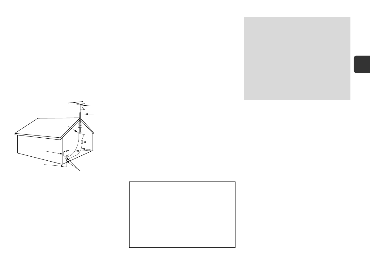
Outdoor Antenna
1 Power lines — When connecting an outdoor antenna,
make sure it is located away from power lines.
2 Outdoor antenna grounding — Be sure the antenna
system is properly grounded to provide protection against
unexpected voltage surges or static electricity build-up.
Article 810 of the National Electrical Code, ANSI/NFPA 70,
provides information on proper grounding of the mast,
supporting structure, and the lead-in wire to the antenna
discharge unit, as well as the size of the grounding unit,
connection to grounding terminals, and requirements for
grounding terminals themselves.
Antenna Grounding According
to the National Electrical Code
GROUND CLAMP
ELECTRIC
SERVICE
EQUIPMENT
POWER SERVICE
GROUNDING
ELECTRODE SYSTEM
(NEC ART 250 PART H)
NEC-NATIONAL ELECTRICAL CODE
ANTENNA
LEAD IN
WIRE
ANTENNA
DISCHARGE
UNIT
(NEC SECTION
810-20)
GROUNDING
CONDUCTORS
(NEC SECTION
810-21)
GROUND CLAMPS
Maintenance
Clean the unit only as recommended in the Operating
Instructions.
Damage Requiring Service
Have the unit serviced by a qualified service technician if:
- The AC power cord or plug has been damaged
- Foreign objects or liquid have gotten inside the unit
- The unit has been exposed to rain or water
- The unit does not seem to operate normally
- The unit exhibits a marked change in performance
- The unit has been dropped, or the cabinet has been damaged
DO NOT ATTEMPT TO SERVICE THE UNIT YOURSELF.
OWNER'S RECORD
Record the model number and serial number of your set
(found at the rear of your set) below. Refer to them when
contacting your Aiwa dealer.
Model No. _____________________________
TABLE OF CONTENTS
PRECAUTIONS .................................... 2
PREPARATIONS ................................... 4
PARTS AND CONTROLS ......................... 5
ADJUSTMENTS BEFORE OPERATION.......... 8
SOUND ADJUSTMENTS.......................... 9
CD OPERATIONS................................ 10
RADIO OPERATIONS ........................... 12
TIMER OPERATIONS ........................... 13
REFERENCE ..................................... 14
System and accessories
Main unit
Speakers
Remote control
FM antenna
AM antenna
En
Serial No. _____________________________
3
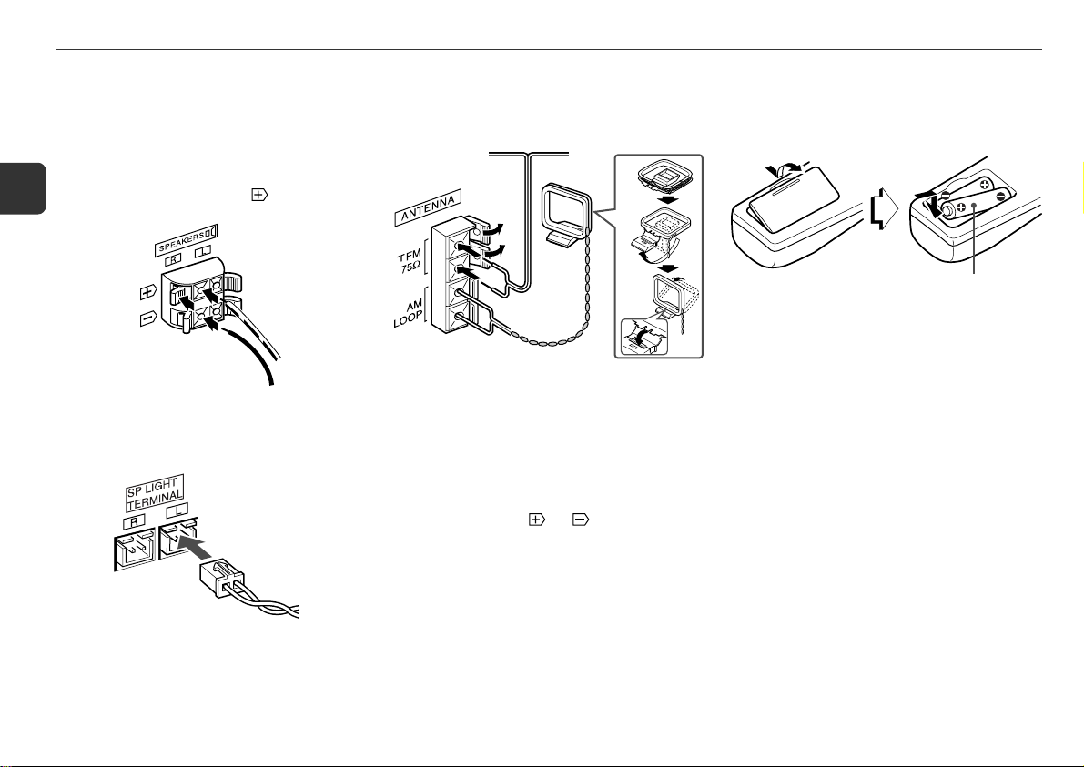
R6(AA)
PREPARATIONS
Connection
Plug in the AC power cord to the AC power outlet after all other
connections are made.
1
Connect the speakers to the main unit.
1 Connect the right speaker to the SPEAKERS R terminals
En
and the left to the SPEAKERS L terminals. The speaker
cords with the stripes go to the
2 Connect the speaker light cord from the right speaker
to the SP LIGHT TERMINAL R jack, and the left to the
SP LIGHT TERMINAL L jack.
terminals.
2
Connect the supplied antennas.
Connect the FM antenna to the FM 75 Ω terminals and
the AM antenna to the AM LOOP terminals.
FM antenna
AM antenna
3
Connect the AC power cord to an AC power outlet.
When the AC power cord is connected to an AC power
outlet for the first time, DEMO appears on the display.
To deactivate the DEMO, press eco/demo and the clock
will flash on the display. For setting the clock, see page 9.
Speakers
•Do not short-circuit the
•Do not leave objects generating magnetism or objects
affected by magnetism near the speakers.
and speaker cord leads.
Remote control
Detach the battery compartment lid at the rear of the remote
control and insert two R6 (size AA) batteries with correct
polarity.
• Replace the batteries with new ones when the operational
distance between the remote control and main unit becomes
shorter.
• Remove the batteries if the unit is not going to be used for
an extended period of time.
•The remote control may not operate if it is used under intense
sunlight or if its line of sight is obstructed.
Antennas
Keep antennas away from metallic objects, electrical
equipment and cords.
FM antenna: Extend fully in a T-shape. If reception is poor,
connect an optional outdoor antenna to the FM 75 Ω terminals.
Be sure to connect the shield braid of the antenna to the 2
terminal.
AM antenna: Rotate to find the best reception.
4
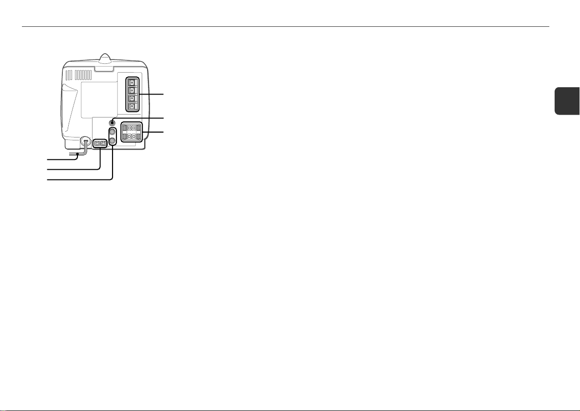
PARTS AND CONTROLS
Main unit: rear
1
2
3
4
5
6
1 AM LOOP and FM 75 Ω terminals
Connect the supplied AM and FM antennas.
2 3 SUPER WOOFER jack
Connect an optional powered sub woofer with a built-in
amplifier to this jack.
3 SPEAKERS3 terminals
Connect the speaker cords of the supplied speakers.
4 AC power cord
5 SP LIGHT TERMINAL jacks
Connect the speaker light cords so that the lights
illuminate from inside the speakers.
6 AUX IN jacks
Accept analog sound signals from external equipment.
Connect external equipment using an optional connecting
cable with RCA phono plugs (red plug to the R jack, white
plug to the L jack). Refer also to the operating instructions
for your equipment.
To switch function to external input, press function
(FUNCTION on the remote control) repeatedly to select
the AUX function.
En
5
 Loading...