

Sony XRH-593-WG Service manual
XR-H592WG/H593WG
SERVICE MANUAL
Photo: XR-H593WG
Dolby noise reduction manufactured under license from Dolby Laboratories Licensing Corporation.
“DOLBY” and the double-D symbol ; are trademarks of Dolby
Laboratories Licensing Corporation.
Notes on Chip Component Replacement
• Never reuse a disconnected chip component.
• Notice that the minus side of a tantalum capacitor may be
damaged by heat.
Model Name Using Similar Mechanism XR-H572A/H573A
Tape Transport Mechanism Type MG-25H-136
FM/AM CASSETTE CAR STEREO
1

TABLE OF CONTENTS
1. DISASSEMBLY
1-1. Cover ..................................................................................3
1-2. Front Panel Assy ................................................................ 3
1-3. Mechanism Deck Block .....................................................4
1-4. Main Board ........................................................................4
2. ASSEMBLY OF MECHANISM DECK
2-1. Arm (Drive) Assy ...............................................................5
2-2. Gear (LDG-D) .................................................................... 5
2-3. Gear (LDG-B) ....................................................................6
2-4. Gear Position Setting .........................................................6
2-5. Chassis (S) Assy.................................................................7
2-6. Lever (Mode)......................................................................7
2-7. Head Plate Assy ................................................................. 8
2-8. Lever (Pinch) Assy .............................................................8
2-9. Main Motor Assy ...............................................................9
2-10. Flywheel (F) .......................................................................9
2-11. Belt (25) ...........................................................................10
2-12. Hanger ..............................................................................10
2-13. Housing ............................................................................ 11
2-14. Arm (Suction) Assy..........................................................11
2-15. Lever (LDG-A) ................................................................12
2-16. Lever (LDG-B).................................................................12
2-17. Gear (Loading FT) ...........................................................13
3. MECHANICAL ADJUSTMENTS...........................14
4. ELECTRICAL ADJUSTMENTS
Tape Section .........................................................................14
Tuner Section........................................................................15
5. DIAGRAMS
5-1. Block Diagram –Tape Section– ....................................... 19
5-2. Block Diagram –Tuner Section–......................................20
5-3. Block Diagram –Control Section– ...................................21
5-4. Printed Wiring Boards –Main Section– ...........................22
5-5. Schematic Diagram –Main Section (1/3)– ....................... 24
5-6. Schematic Diagram –Main Section (2/3)– ....................... 25
5-7. Schematic Diagram –Main Section (3/3)– ....................... 26
5-8. Schematic Diagram –Display Section–............................27
5-9. Printed Wiring Boards –Display Section– .......................28
5-10. IC Pin Description............................................................32
6. EXPLODED VIEWS
6-1. Chassis Section ................................................................34
6-2. Front Panel Section .......................................................... 35
6-3. Mechanism Deck Section (1) ...........................................36
6-4. Mechanism Deck Section (2) ...........................................37
6-5. Mechanism Deck Section (3) ...........................................38
7. ELECTRICAL PARTS LIST ...................................39
2
SECTION 1
DISASSEMBLY
Note : Follow the disassembly procedure in the numerical order given.
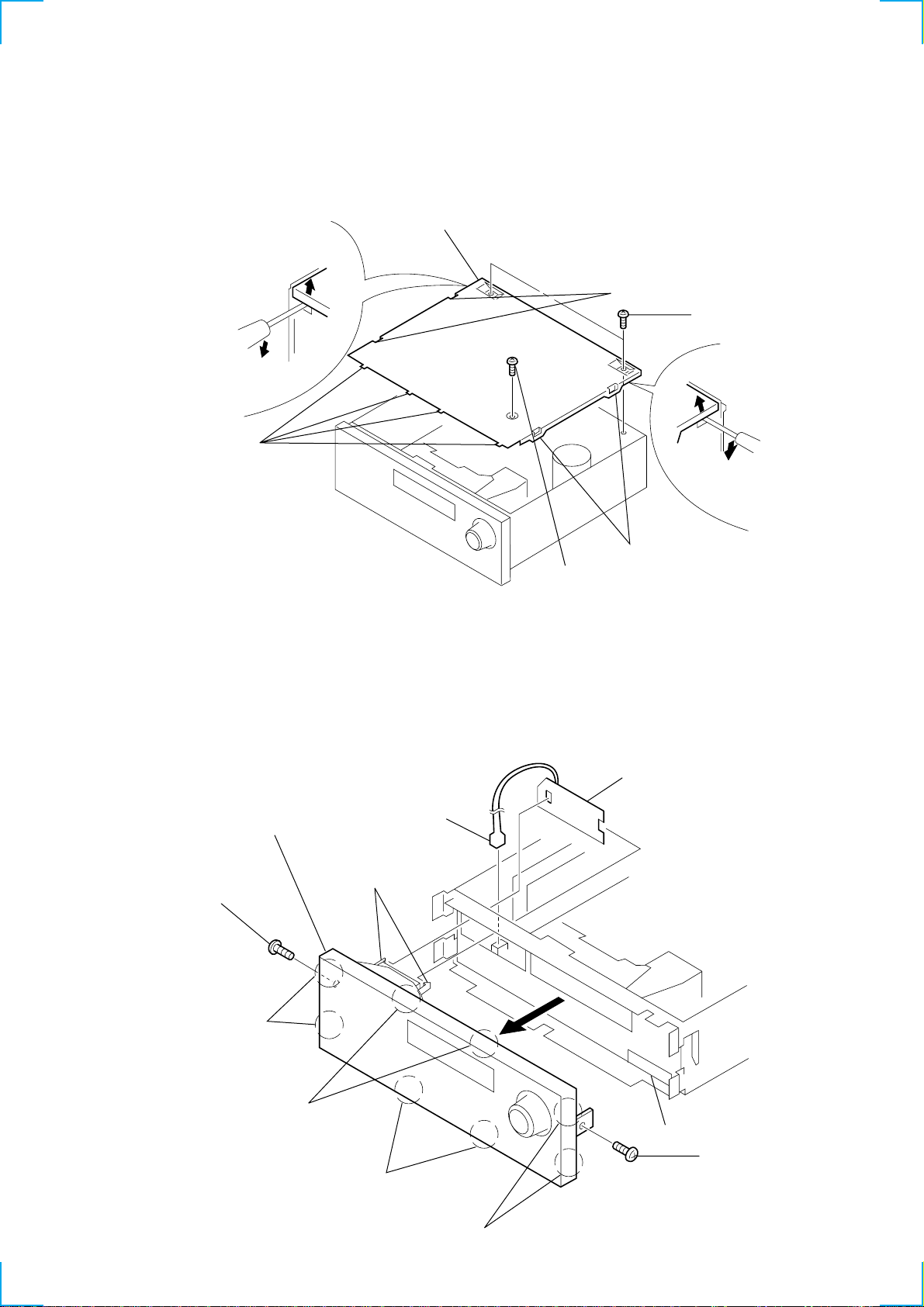
1-1. COVER
6 cover
5 claws
4 claws
1 P 2.6x6
1-2. FRONT PANEL ASSY
Note : When removing the LAMP board from the holder (B), take
care not to bend or break the claw of the holder.
2 CN802
0 front panel assy
claws
(holder (B))
3 screw (TP)
3 claws
2 P 2.6x8
1 LAMP board
5 claws
6 claws
9 CN800
4 screw (TP)
7 claws
8 claws
3
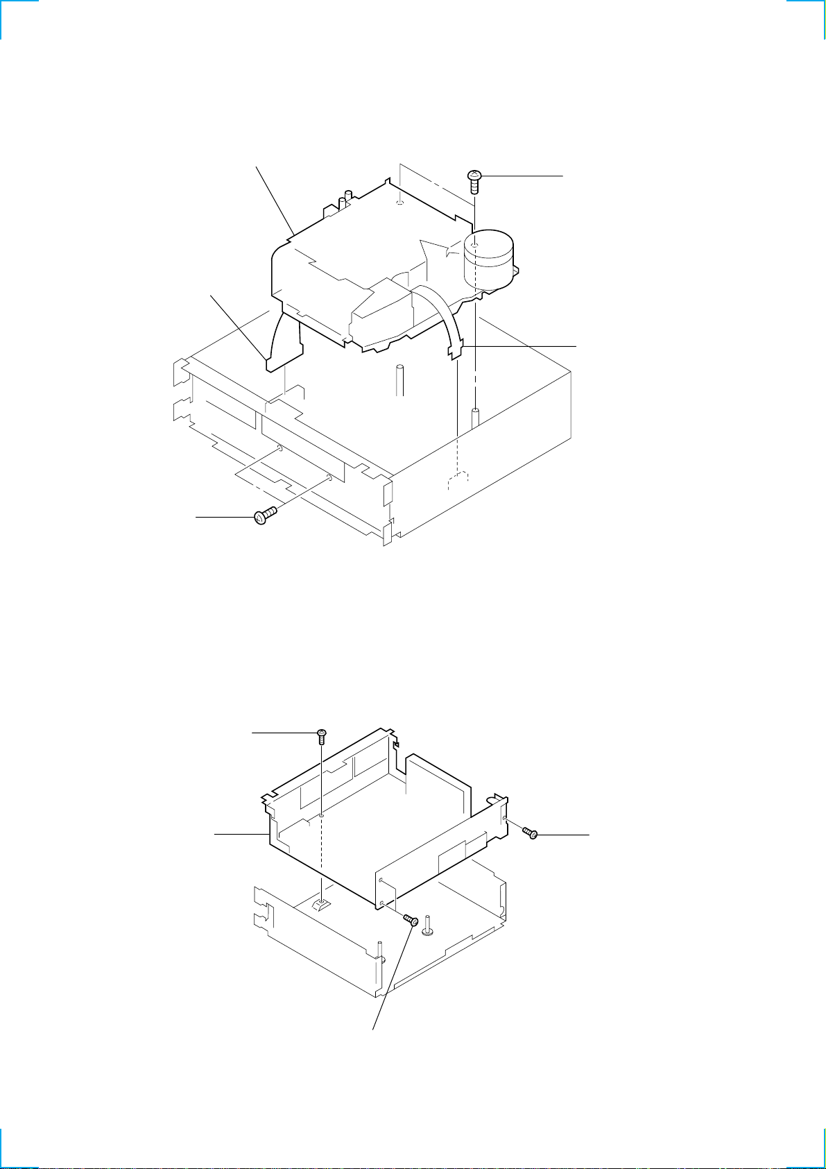
1-3. MECHANISM DECK BLOCK
6
1 P 2.6x6
5 mechanism deck block
1 P 2.6x6
4 CNP501
3 CNP401
1-4. MAIN BOARD
4 MAIN board
3 P 2.6x6
1 P 2.6x
2 P 2.6x6
4
D
SECTION 2
ASSEMBLY OF MECHANISM DECK
Note : Follow the assembly procedure in the numerical order given.
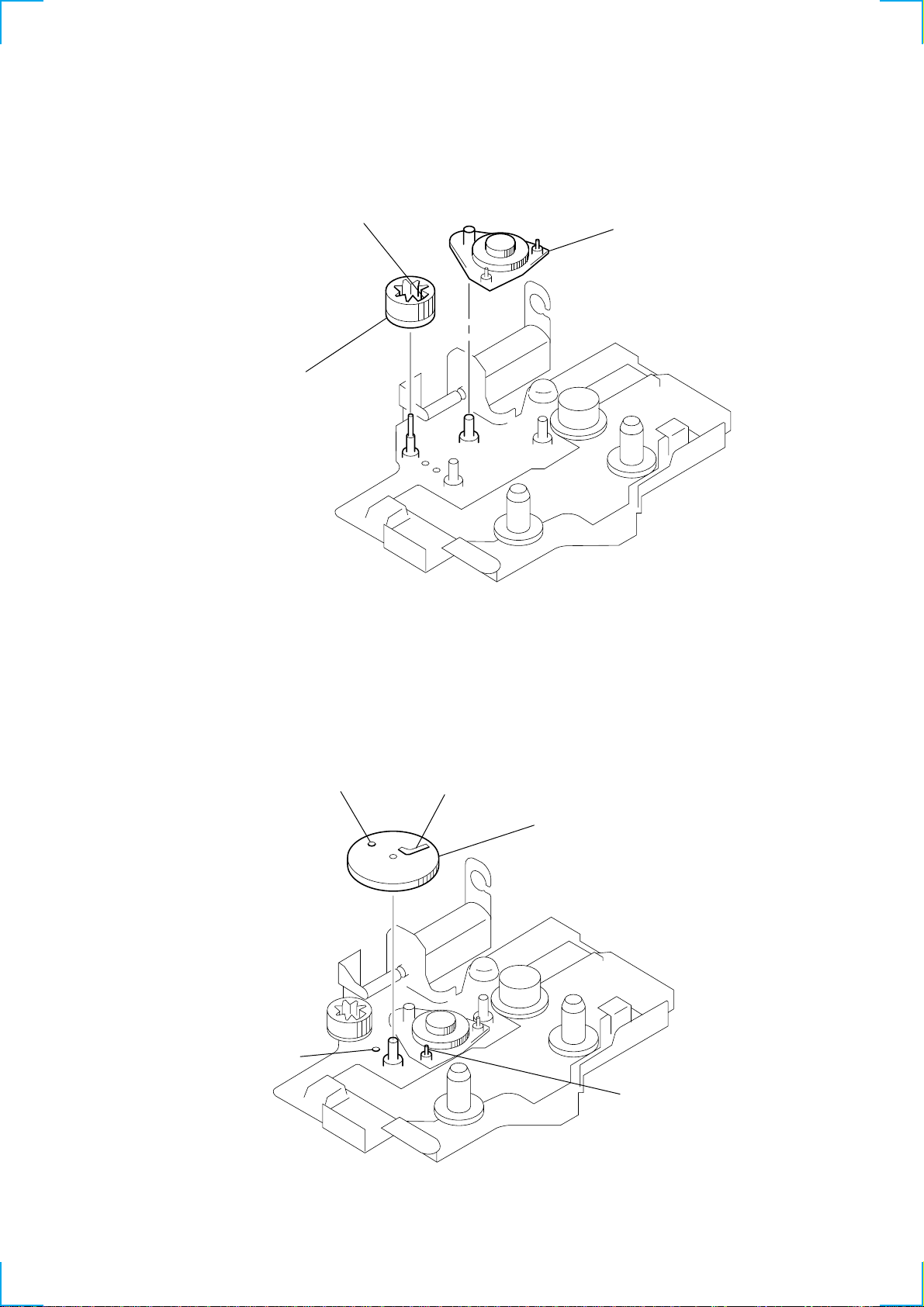
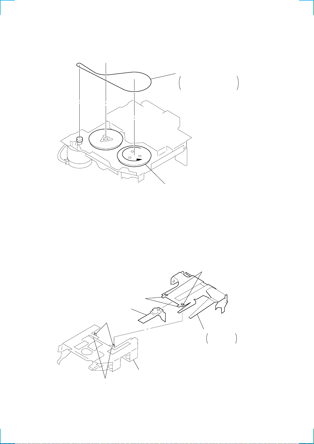
2-1. ARM (DRIVE) ASSY
Part A
2 gear (LDG-FB)
(Align part A as
shown in the figure.)
1 arm (drive) assy
2-2. GEAR (LDG-D)
B
A
D
1 gear (LDG-D)
(Position A with B and C with
and install them.)
C
5
D
e
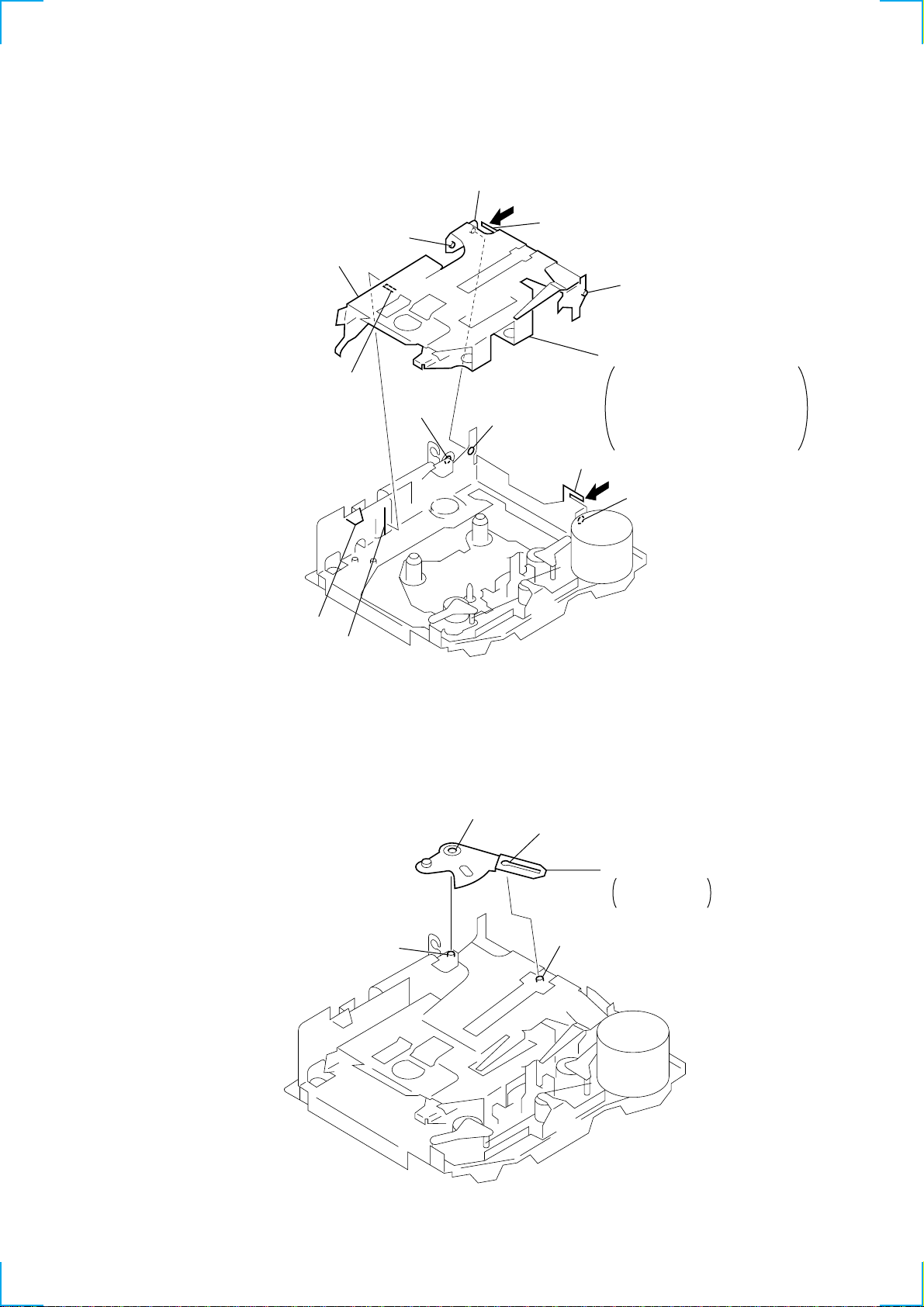
2-3. GEAR (LDG-B)
3 gear (LDG-B)
2 stopper washer
B
D
1 gear (LDG-E)
(Position A with B and C with
and install them.)
A
C
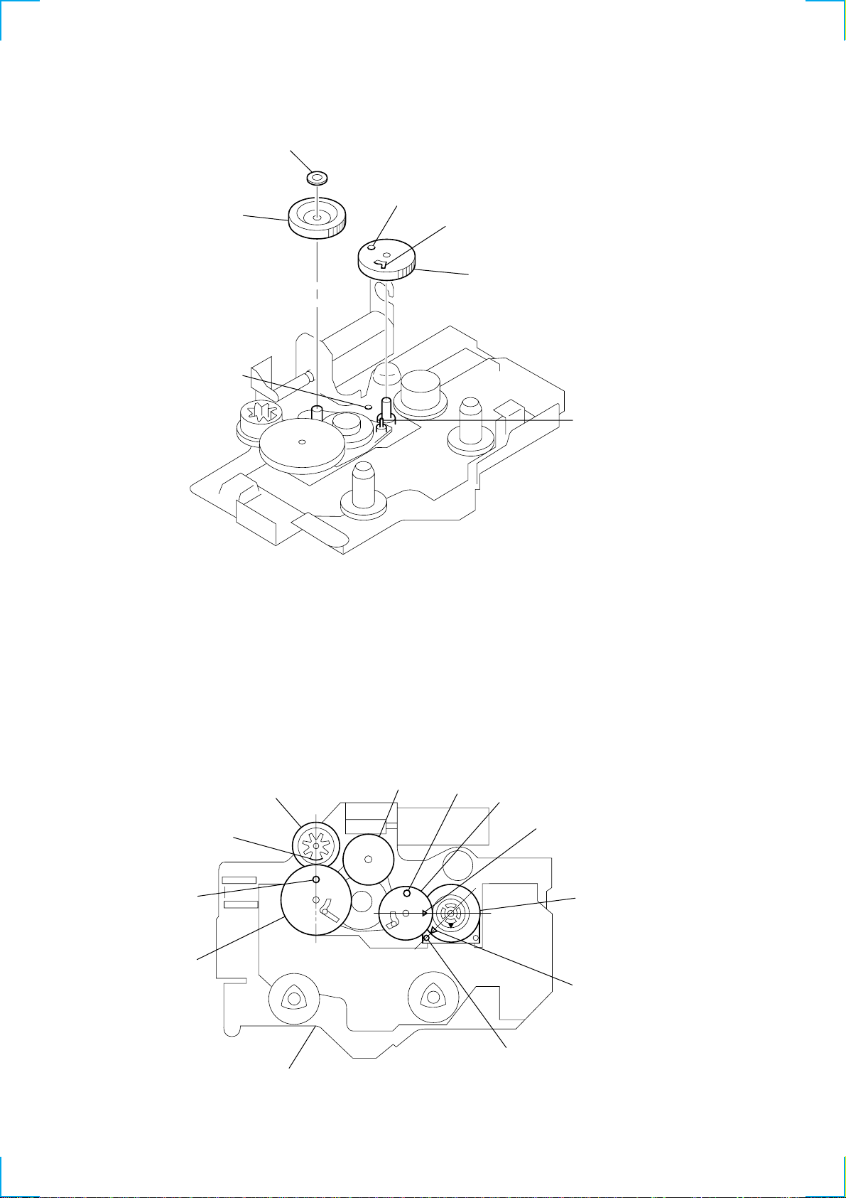
2-4. GEAR POSITION SETTING
• Align A with B.
• Align B with the hole in the chassis (S) assy.
• Align C with the hole in the chassis (S) assy.
• Face D to the rotary slide switch.
• Align E with F.
gear (LDG-FB)
A
B
gear (LDG-D)
gear (LDG-B)
C
gear (LDG-E)
D
switch, rotary slid
E
F
chassis (S) assy
6
)
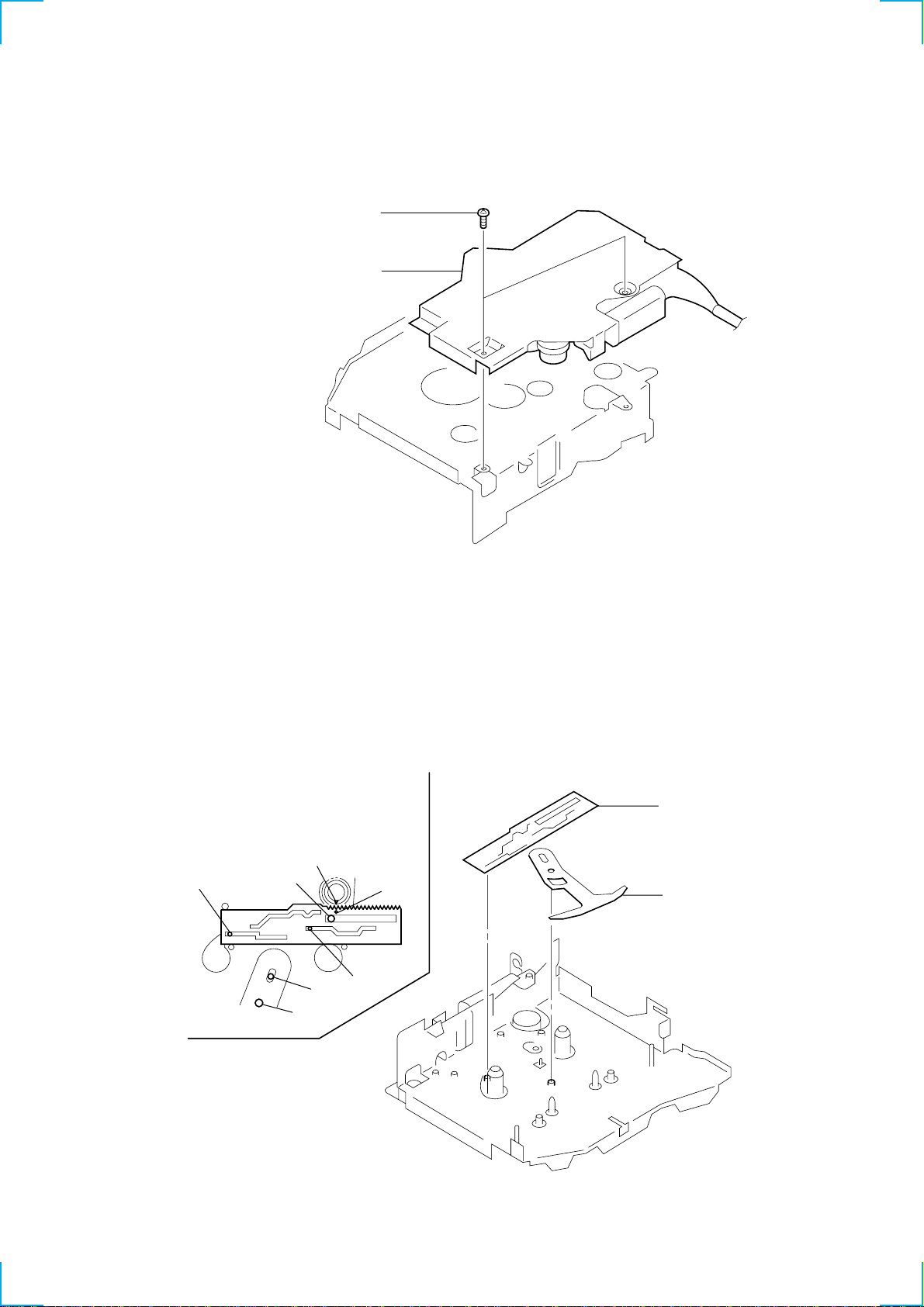
2-5. CHASSIS (S) ASSY
1 chassis (S) assy
2 PS 2x4
2-6. LEVER (MODE)
• Align A of rotary slide switch with
B of lever (mode).
• Check that each of C through G
is put in the groove.
E
1 lever (mode)
A
C
F
G
B
D
2 lever (pinch selection
7
y
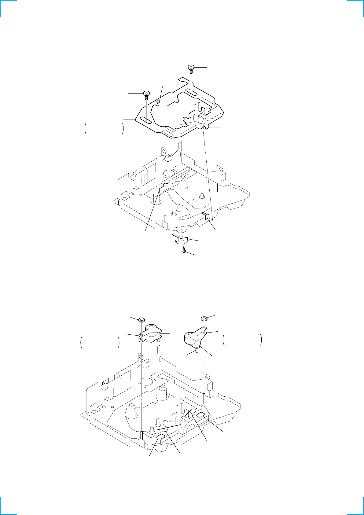
2-7. HEAD PLATE ASSY
1 head plate assy
• Insert A into B.
• Insert C into D.
2 step screw (HP)
C
3 step screw (HP)
A
2-8. LEVER (PINCH) ASSY
1 lever (pinch R) assy
• Insert A into B.
• Hook C to D.
2 washer (pinch)
D
5 P 2x2
D
A
E
B
4 head base retainer spring
4 washer (pinch)
3 lever (pinch F) ass
• Insert E into F.
• Hook G to H.
H
F
G
B
C
8
y
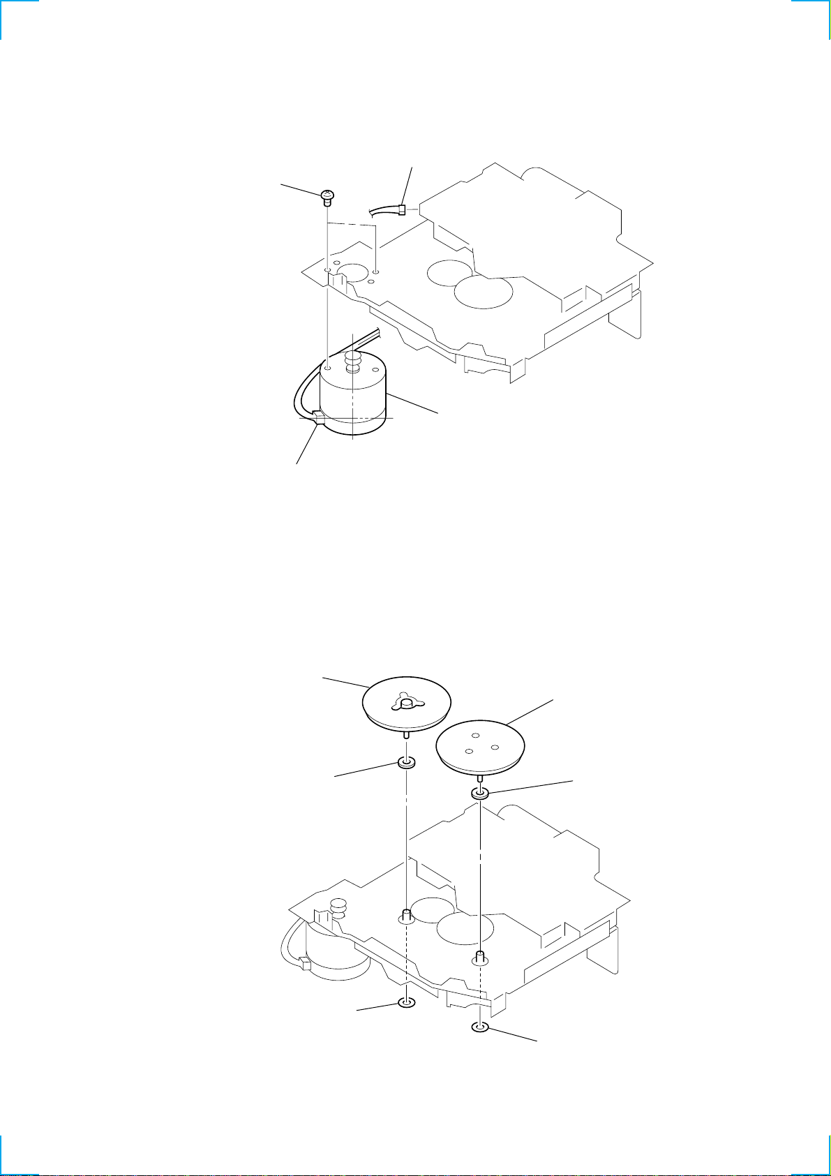
2-9. MAIN MOTOR ASSY
4 P 2x2
1 CN103
3 main motor assy
2 Align the motor terminal with
the position given in the diagrams.
2-10. FLYWHEEL (F)
5 flywheel (F)
4 washer
6 washer
2 clutch (FR) ass
1 washer
3 washer
9
2-11. BELT (25)
1 belt (25)
• Turn the clutch (FR) assy
in the arrowed direction and
correct twist at the belt (25).
clutch (FR) assy
2-12. HANGER
D
A
1 catcher assy
C
2 hanger
• Fit A into B
and C into D.
housing
B
10
2-13. HOUSING
Note : Install the housing with care to avoid
contact with the pinch roller and head.
G
E
A
C
F
B
D
I
L
H
1 housing
• Put A to below B.
• Insert C into D.
• Insert E into F.
• Put G and H into I and J.
• Bend K and L toward the
arrowed directions respectively.
K
J
2-14. ARM (SUCTION) ASSY
C
D
B
1 arm (saction) assy
• Insert A into B.
• Align C with D.
A
11
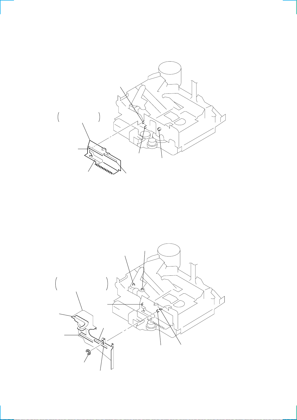
2-15. LEVER (LDG-A)
1 lever (LDG-A)
• Fit A into B, C into D
and E into F.
B
A
F
D
2-16. LEVER (LDG-B)
1 lever (LDG-B)
• Fit A into B and C into D.
• Fit E into F.
• Put G and H into J.
I
E
B
C
H
G
12
A
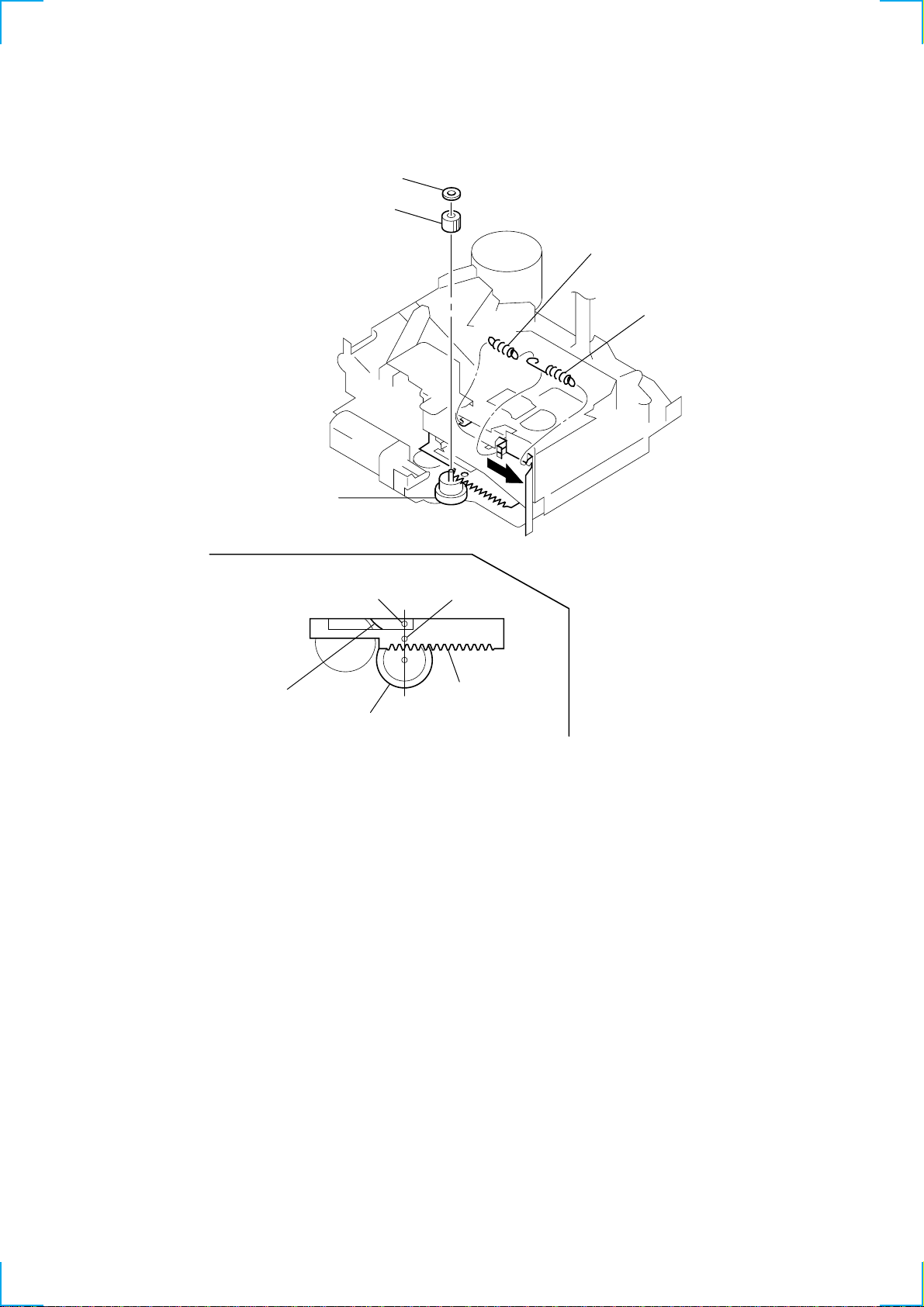
2 stop ring 2.0
E
D
C
F
)
2-17. GEAR (LOADING FT)
3 gear (loading FT)
(• Fit A into B.)
gear (LDG-FB)
4 washer
2 tension spring (LD-2)
1 tension spring (LD-1
gear (LDG-D)
B
gear (LDG-FB)
A
gear (LDG-A)
13
r
SECTION 3
MECHANICAL ADJUSTMENTS
SECTION 4
ELECTRICAL ADJUSTMENTS
PRECAUTION
1. Wipe the following components with an absorbent cotton c loth
moistened with alcohol before adjustment :
PB head Pinch roller
Idler Rubber belt
Capstan
2. Demagnetize the PB head using a head demagnetizer.
3. Be careful not to use a magnetized screwdriver.
4. After the adjustment is completed, lock the adjustment parts
using screws.
5. Unless otherwise specified, make adjustments at the specified
voltage (14.4V).
Torque Measurement
Mode Torque Meter Meter Reading
39.3 – 78.4 mN • m
FWD 40 – 80 g • cm
CQ-102C
FWD
Back T ension
REV 40 – 80 g • cm
CQ-102RC
REV
Back T ension
FF, REW CQ-201B 50 – 180 g • cm
(0.56 – 1.11 oz • inch)
0.05 – 0.49 mN • m
0.5 – 5.0 g • cm
(0.01 – 0.07 oz • inch)
39.3 – 78.4 mN • m
(0.56 – 1.11 oz • inch)
0.05 – 0.49 mN • m
0.5 – 5.0 g • cm
(0.01 – 0.07 oz • inch)
4.91 – 17.65 mN • m
(0.7 – 2.5 oz • inch)
See the adjustment location from on page 17 for the adjustment.
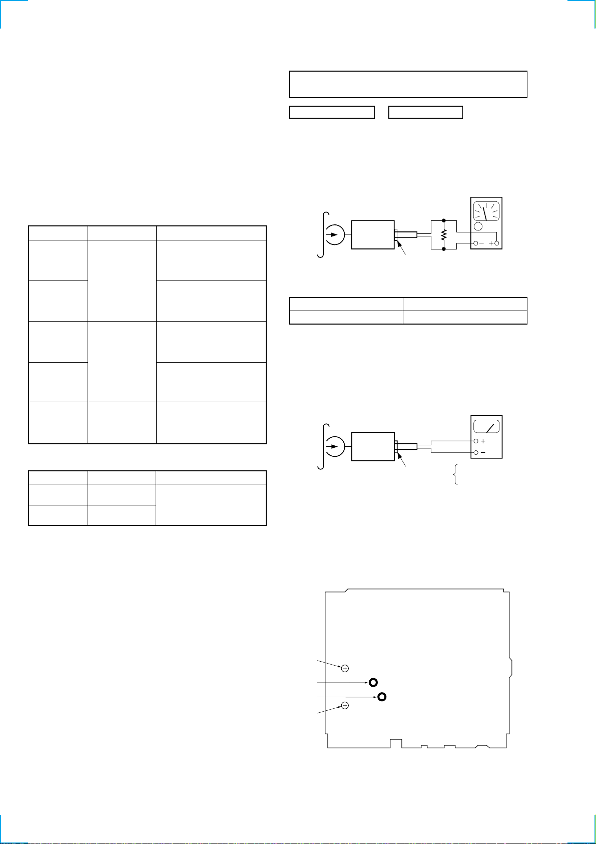
TAPE SECTION
0 dB = 0.775 V
T ape Speed Adjustment
Procedure :
1. Put the set into the FWD PB mode.
speed checker
test tape
WS-48A
(3 kHz, 0 dB)
4 Ω
set
SPEAKER OUT
or
frequency counte
Specification : Constant speed
Speed checker Frequency counter
–1 to + 3 % 2,970 to 3,090 Hz
Adjustment Location : See page 17.
DOLBY Level Adjustment
Setting :
test tape
P-4-D400
(400 Hz, 0 dB)
set
level meter
T ape T ension Measurement
Mode Tension Meter Meter Reading
FWD CQ-403A
more than 558.4 mN
more than 60 g
REV CQ-403R
(more than 2.12 oz)
main board
TP (DOLBY)
L-CH
R-CH
Procedure :
1. Put the set into the FWD PB mode.
2. Adjust RV402 (L-CH) and RV401 (R-CH) so that level meter
reading is –6.2 ± 1 dB (0.34 to 4.34 V).
Adjustment Location :
-MAIN BOARD (SIDE B)-
RV401
TP
(RCH)
TP
(LCH)
RV402
14
 Loading...