

Sony XRCA-610-X Service manual
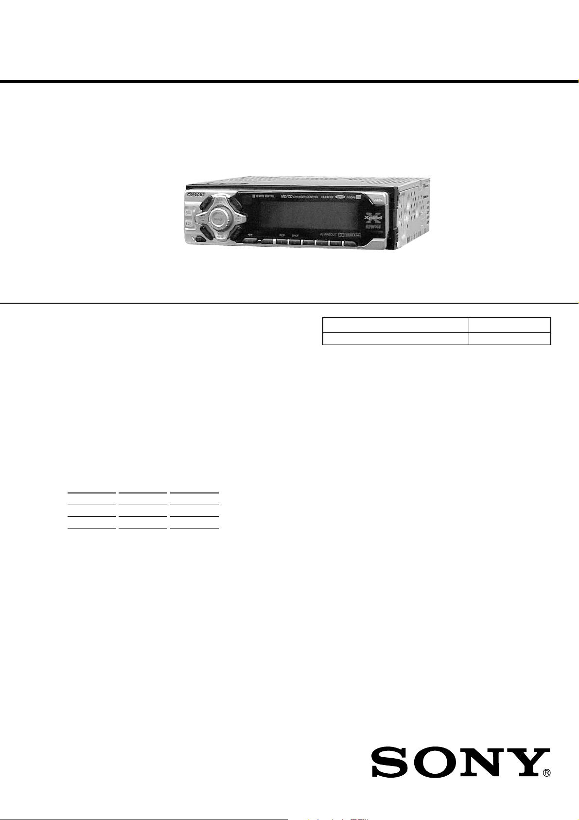
XR-CA610X
SERVICE MANUAL
Ver 1.1 2001.05
Manufacutured under license from Dolby
Laboratories. “Dolby” and the double-D symbol are
trademarks of Dolby Laboratories.
SPECIFICATIONS
US Model
Model Name Using Similar Mechanism XR-C5300X
Tape Transport Mechanism Type MG-25F-136
AUDIO POWER SPECIFICATIONS
POWER OUTPUT AND TOTAL HARMONIC DISTORTION
23.2 watts per channel minimum
4 channels driv en from 20 Hz to 20 kHz
Cassette Player section
Tape track 4-track 2-channel stereo
Wow and flutter 0.08 % (WRMS)
Frequency response 30 – 18,000 Hz
Signal-to-noise ratio
Cassette type Dolby B NR Dolby NR off
TYPE II, IV 67 dB 61 dB
TYPE I 64 dB 58 dB
Tuner section
FM
Tuning range 87.5 – 107.9 MHz
Antenna terminal External antenna connector
Intermediate frequency 10.7 MHz/450 kHz
Usable sensitivity 8 dBf
Selectivity 75 dB at 400 kHz
Signal-to-noise ratio 66 dB (stereo),
Harmonic distortion at 1 kHz
Separation 35 dB at 1 kHz
Frequency response 30 – 15,000 Hz
72 dB (mono)
0.6 % (stereo),
0.3 % (mono)
continuous av era ge po wer i nto 4 ohms,
with no more than 5% total harmonic distortion.
AM
Tuning range 530 – 1,710 kHz
Antenna terminal External antenna connector
Intermediate frequency 10.7 MHz/450 kHz
Sensitivity 30 µV
Power amplifier section
Outputs Speaker outputs
Speaker impedance 4 – 8 ohms
Maximum power output
General
Outputs
Inputs Telephone A TT control lead
Tone controls Bass ±10 dB at 62 Hz
(sure seal connectors)
52 W × 4 (at 4 ohms)
Audio outputs (2)
Power antenna relay control
lead
Power amplifie r con trol l ead
BUS control input
connector
BUS audio input connector
Remote controller input
connector
Antenna input connector
Treble ±10 dB at 16 kHz
Loudness 100 Hz +8 dB
Power requirements 12 V DC car battery
Dimensions Approx. 178 × 50 × 176
Mounting dimensions Approx. 182 × 53 × 161
Mass Approx. 1.2 kg (2 lb 10 oz)
Supplied accessories Card remote commander
Note
This unit cannot be connected to a digital preamplifier
or an equalizer.
Design and specifications are subject to change
without notice.
10 kHz +2 dB
(negative ground)
1
mm (7
/8 × 2 × 7 in.)
(w/h/d)
1
mm (7
/4 × 21/8 × 63/8 in.)
(w/h/d)
Parts for installation and
connections (1 set)
Front panel case (1)
9-870-274-12 Sony Corporation
2001E0500-1 e Vehicle Company
C 2001.5 Shinagawa Tec Service Manual Production Group
FM/AM CASSETTE CAR STEREO

XR-CA610X
TABLE OF CONTENTS
1. GENERAL
Location of Controls ....................................................... 3
2. DISASSEMBLY
2-1. Disassembly Flow ........................................................... 9
2-2. Sub Panel Assy................................................................ 9
2-3. Mechanism Deck (MG-25F-136) ................................... 10
2-4. MAIN Board ................................................................... 10
2-5. Heat Sink (2P) ................................................................. 11
3. ASSEMBLY OF MECHANISM DECK
3-1. Assembly Flow................................................................ 12
3-2. Housing ........................................................................... 12
3-3. Arm (Suction) ................................................................. 13
3-4. Lever (LDG-A)/(LDG-B) ............................................... 13
3-5. Gear (LDG-FT) ............................................................... 14
3-6. Guide (C)......................................................................... 14
3-7. Mounting Position of Capstan/reel Motor (M901) ........ 15
4. MECHANICAL ADJUSTMENTS....................... 16
5. ELECTRICAL ADJUSTMENTS
Tape Deck Section .......................................................... 17
Tuner Section .................................................................. 17
Notes on chip component replacement
• Never reuse a disconnected chip component.
• Notice that the minus side of a tantalum capacitor may be dam-
aged by heat.
Flexible Circuit Board Repairing
• Keep the temperature of the soldering iron around 270 ˚C during repairing.
• Do not touch the soldering iron on the same conductor of the
circuit board (within 3 times).
• Be careful not to apply force on the conductor when soldering
or unsoldering.
6. DIAGRAMS
6-1. Block Diagram –TUNER/TAPE Section – ................... 19
6-2. Block Diagram – MAIN Section – ................................ 20
6-3. Block Diagram – DISPLAY/KEY CONTROL/
BUS CONTROL/POWER SUPPLY Section – .............. 21
6-4. Note for Printed Wiring Boards and
Schematic Diagrams ....................................................... 22
6-5. Printed Wiring Board – MAIN Board – ........................ 23
6-6. Schematic Diagram – MAIN Board (1/3) – .................. 24
6-7. Schematic Diagram – MAIN Board (2/3) – .................. 25
6-8. Schematic Diagram – MAIN Board (3/3) – .................. 26
6-9. Printed Wiring Board – SUB Board – ........................... 27
6-10. Schematic Diagram – SUB Board – .............................. 27
6-11. Printed Wiring Board – KEY Board –........................... 28
6-12. Schematic Diagram – KEY Board – ............................. 29
6-13. IC Pin Function Description ........................................... 32
7. EXPLODED VIEWS
7-1. General Section ............................................................... 35
7-2. Front Panel Section ......................................................... 36
7-3. Mechanism Deck Section (MG-25F-136) ...................... 37
8. ELECTRICAL PARTS LIST ............................... 38
2
SECTION 1
GENERAL
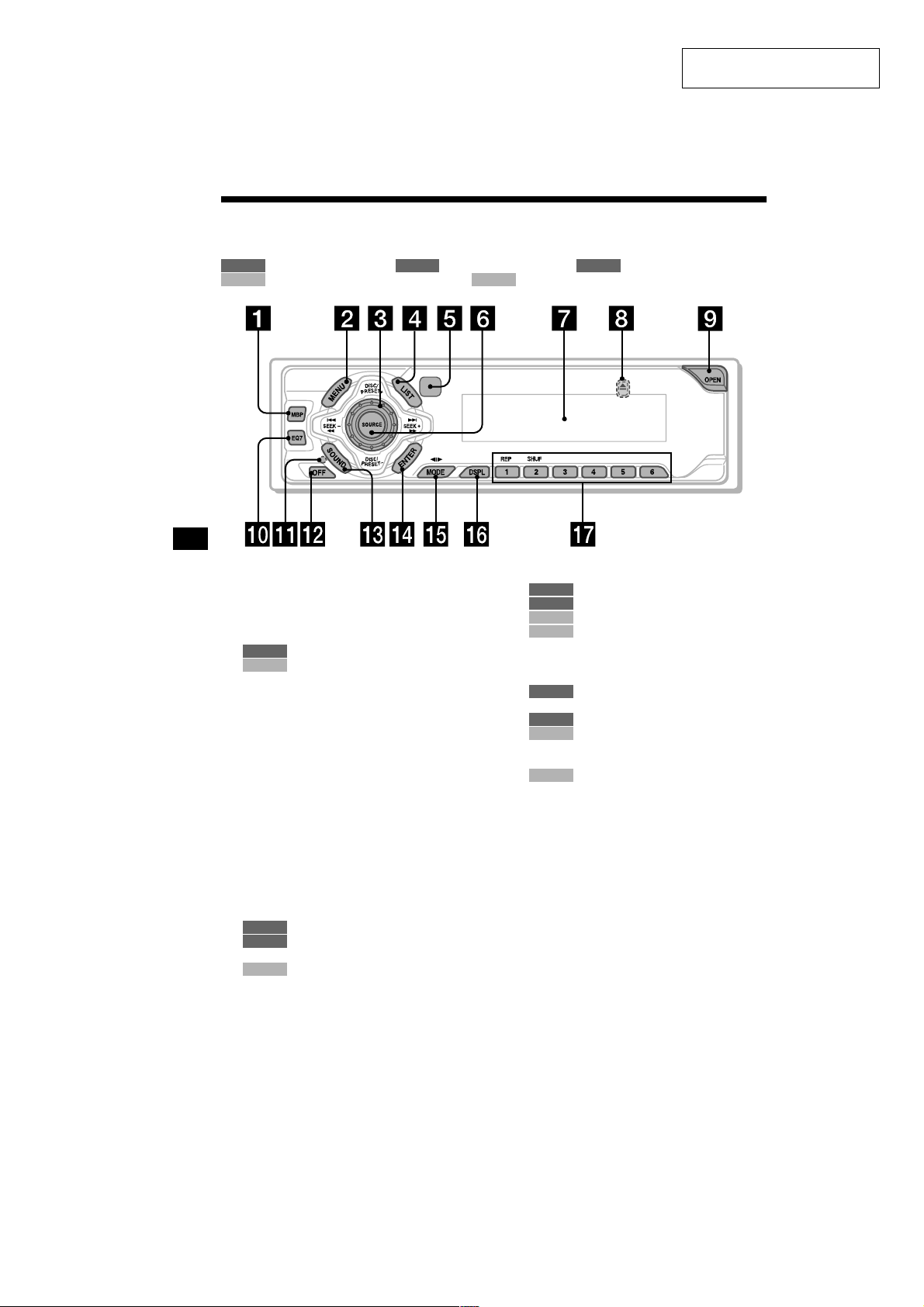
Location of controls
Refer to the pages listed for details.
: During tape playback : During radio reception : During menu mode
TAPE RADIO MENU
: During CD/MD playback (optional) : During TV reception (optional)
CD/MD
TV
XR-CA610X
This section is extracted from
instruction manual.
a MBP button 16
b MENU button 8, 9, 10, 11, 12, 15, 16,
17, 19, 20, 21, 22
c Volume control dial
d LIST button
e Receptor for the card remote
f SOURCE (Power on/Tape/Radio/CD/
g Di splay window
h Z (eject) button (located on the front side
i OPEN button 7, 9
j EQ7 button 16
k RESET button (located on the fr ont si de of
l OFF (Stop/Power off) button* 5, 7, 9,
m SOUND button 14, 16
n ENTER button
11, 12
RADIO
19, 20
CD/MD
commander
MD/TV) button 5, 9, 10, 11, 16, 17, 19,
21, 22, 23
of the unit, behind the front panel) 9, 23
the unit, behind the front panel) 7
17
12
RADIO
8, 9, 10, 11, 12, 15, 16, 17, 19,
MENU
20, 21, 22, 23
19, 20
CD/MD
o MODE (o) button
9
TAPE
10, 11
RADIO
17, 19
CD/MD
21
TV
p DSPL (display mode change) button
12, 18, 19
q Number buttons
TAPE
(1) REP 9
10, 11
RADIO
CD/MD
(1) REP 18
(2) SHUF 18
22
TV
* Warning when installing in a car without
an ACC (accessory) position on the
ignition switch
After turning off the ignition, be sure to press
(OFF) on the unit for 2 seconds to turn off the
clock d isplay.
Otherwise, the clock disp la y doe s not turn off and
this causes battery drain.
4
3
XR-CA610X
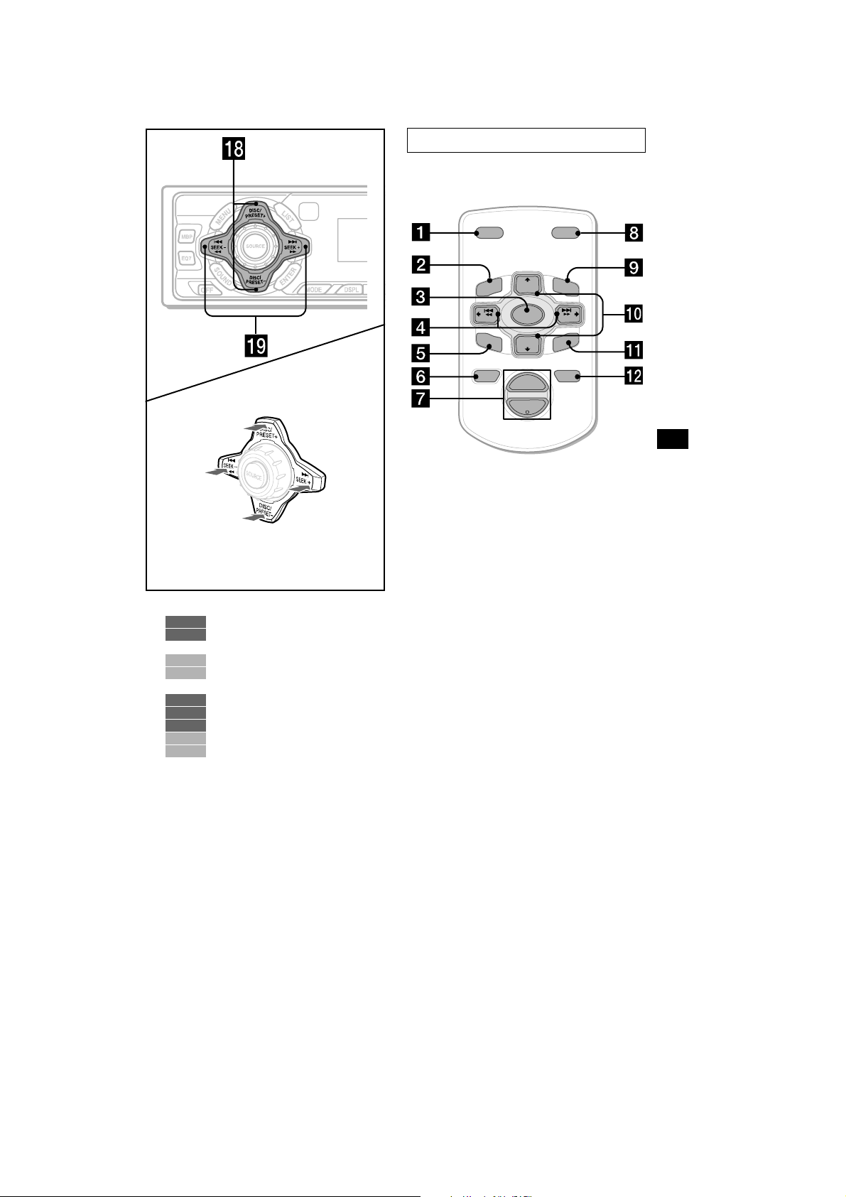
Card remote commander RM-X114
DSPL MODE
+
PRESET
LIST
+
DISC
MENU
(DISC/PRESET)
(+): to select upwards
(SEEK)
(–): to select
leftwards/
.
(DISC/PRESET)
(–): to select downwards
In menu mode, the currently selectable button (s)
of these four are indicated with a “ M” in the display.
(SEEK)
(+): to select
rightwards/
>
r DISC/PRESET buttons (+/–)
10, 11, 12
RADIO
8, 9, 10, 11, 12, 15, 16, 17, 19,
MENU
20, 21, 22
17, 19, 20
CD/MD
21
TV
s SEEK buttons (–/+)
9
TAPE
10, 11
RADIO
8, 9, 14, 15, 16, 17, 21
MENU
17, 19, 20
CD/MD
22, 23
TV
–
SEEK
SOUND
SOURCE
DISC
PRESET –
+
VOL
+
SEEK
–
ENTER
ATTOFF
–
The corresponding buttons of the card
remote commander control the same
functions as those on this unit.
a DSPL button
b MENU button
c SOURCE button
d SEEK (</,) buttons
e SOUND button
f OFF button
g VOL (–/+) buttons
h MODE button
i LIST button
j DISC/PRESET(M/m) buttons
k ENTER button
l ATT button
Note
If the units is turned off by pressing (OFF) for 2
seconds, it cannot be operated with the card remote
commander unless (SOURCE) on the unit is pressed,
or a cassette is inser ted to activate the unit first.
Tip
Refer to “Replacing the lithium battery” for details on
how to replace the batteries (page 24).
5
4
2
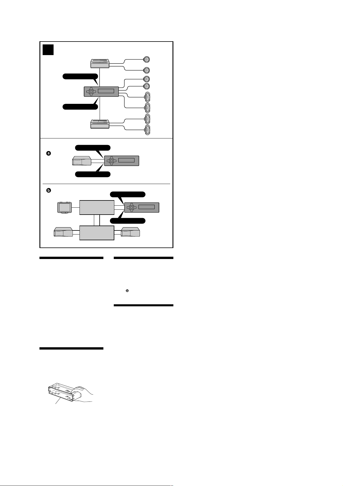
A
XR-CA610X
AUDIO OUT FRONT
AUDIO OUT REAR
B
BUS AUDIO IN
BUS CONTROL IN
TV tuner unit
Syntoniseur de
télévision
Source selector
Sélecteur de source
Cautions
•This unit is designed for negative ground 12 V
DC operation only.
•Do not get the wires under a screw, or caught
in moving parts (e.g. seat railing).
•Before making connections, disconnect the
ground terminal of the car battery to avoid
short circuits.
•Connect the yellow and red power input leads
only after all other leads have been connected.
•Run all ground wires to a common ground
point.
•Be sure to insulate any loose unconnected
wires with electrical tape for safety.
Notes on the power supply cord (yellow)
•When connecting this unit in combination with
other stereo components, the connected car
circuit’s rating must be higher than the sum of
each component’s fuse.
•When no car circuits are rated high enough,
connect the unit directly to the battery.
Parts Iist (1)
The numbers in the list are keyed to those in the
instructions.
Caution
Handle the bracket 1 carefully to avoid injuring
your fingers.
1
BUS AUDIO IN
*
BUS CONTROL IN
*
not supplied
*
non fourni
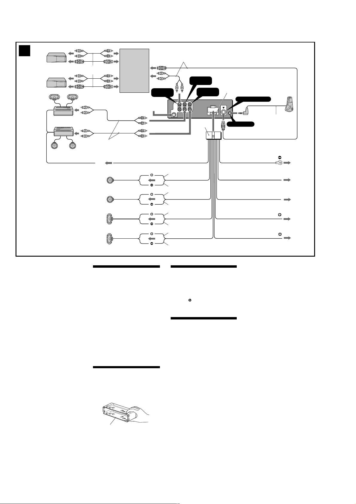
Connection example (2)
Notes (2-A)
• Be sure to connect the ground cord before
connecting the amplifier.
• If you connect an optional power amplifier and
do not use the built-in amplifier, the beep
sound will be deactivated.
Tip (2-B-
)
For connecting two or more changers, the source
selector XA-C30 (optional) is necessary.
Connection diagram (3)
1
To a metal surface of the car
First connect the black ground lead, then
connect the yellow and red power input
leads.
2
To the power antenna control lead or power
supply lead of antenna booster amplifier
Notes
• It is not necessary to connect this lead if
there is no power antenna or antenna
booster, or with a manually-operated
telescopic antenna.
• When your car has a built-in FM/AM
antenna in the rear/side glass, see “Notes
on the control and power supply leads.”
3
To AMP REMOTE IN of an optional power
amplifier
This connection is only for amplifiers.
Connecting any other system may damage
the unit.
4
To the interface cable of a car telephone
5
To the +12 V power terminal which is
energized in the accessory position of the
ignition key switch
Notes
• If there is no accessory position, connect to
the +12 V power (battery) terminal which is
energised at all times.
Be sure to connect the black ground to it
first.
• When your car has a built-in FM/AM
antenna in the rear/side glass, see “Notes
on the control and power supply leads.”
6
To the +12 V power terminal which is
energised at all times
Be sure to connect the black ground to it
first.
5
XR-CA610X
3
Supplied with the CD/MD changer
Fourni avec le changeur de CD/MD
RCA pin cord (not supplied)
Cordon à broche RCA (non fourni)
3
Left
Gauche
Right
Droit
Left
Gauche
Right
Droit
Source selector
Sélecteur de source
from car antenna adaptor
à partir de l’adaptateur de
l’antenne de la voiture
AMP REM
Max. supply current 0.3 A
Courant max. fourni 0,3 A
Supplied with XA-C30
Fourni avec le XA-C30
BUS AUDIO
IN
L
R
AUDIO OUT
AUDIO OUT
BUS
FRONT
REAR
AUDIO
Blue/white striped
Rayé bleu/blanc
White
Blanc
White/black striped
Rayé blanc/noir
Gray
Gris
Gray/black striped
Rayé gris/noir
Green
Vert
Green/black striped
Rayé vert/noir
Purple
Mauve
Purple/black striped
Rayé mauve/noir
AUDIO OUT
REAR
AUDIO OUT
FRONT
8
Fuse (10 A)
Fusible (10 A)
REMOTE IN
Black
Noir
Blue
Bleu
Light blue
Bleu ciel
Red
Rouge
Yellow
Jaune
BUS CONTROL IN
Insert with the cord
upwards.
Insérez avec le câble
vers le haut.
Max. supply current 0.1 A
Courant max. fourni 0,1 A
(XR-CA610X only)
(XR-CA610X seulemente)
ANT REM
ATT
1
2
4
5
6
Notes on the control and power supply leads
• The power antenna control lead (blue) supplies
+12 V DC when you turn on the tuner.
• When your car has built-in FM/AM antenna in the
rear/side glass, connect the power antenna control
lead (blue) or the accessory power input lead (red)
to the power terminal of the existing antenna
booster. For details, consult your dealer.
• A power antenna without relay box cannot be
used with this unit.
Memory hold connection
When the yellow power input lead is connected,
power will always be supplied to the memory circuit
even when the ignition key is turned off.
Notes on speaker connection
• Before connecting the speakers, turn the unit off.
• Use speakers with an impedance of 4 to 8 ohms,
and with adequate power handling capacities to
avoid its damage.
• Do not connect the speaker terminals to the car
chassis, or connect the terminals of the right
speakers with those of the left speaker.
• Do not connect the ground lead of this unit to the
negative (–) terminal of the speaker.
• Do not attempt to connect the speakers in parallel.
• Connect only passive speakers. Connecting active
speakers (with built-in amplifiers) to the speaker
terminals may damage the unit.
Précautions
•Cet appareil est conçu pour fonctionner sur
courant continu de 12 V avec masse négative.
•Evitez de fixer des vis sur les câbles ou de
coincer ceux-ci dans des pièces mobiles (par
exemple, armature de siège).
•Avant d’effectuer des raccordements, éteignez
le moteur pour éviter les courts-circuits.
•Branchez les fils d’entrée d’alimentation jaune
et rouge seulement après avoir terminé tous les
autres branchements.
•Rassemblez tous les fils de terre en un point
de masse commun.
•Veillez à isoler avec du chatterton tout fil lâche
non raccordé.
Remarques sur le cordon d’alimentation (jaune)
•Lorsque cet appareil est raccordé à d’autres
éléments stéréo, la valeur nominale des circuits
de la voiture raccordée doit être supérieure à la
somme des fusibles de chaque élément.
•Si aucun circuit de la voiture n’est assez
puissant, raccordez directement l’appareil à la
batterie.
Liste des composants ( 1)
Les numéros de l’illustration correspondent à
ceux des instructions.
Attention
Manipulez précautionneusement le support 1
pour éviter de vous blesser aux doigts.
1
Exemple de raccordement (2)
Remarques (2-A)
• Raccordez d’abord le fil de masse avant de
connecter l’amplificateur.
• Si vous raccordez un amplificateur de puissance et
que vous n’utilisez pas l’amplificateur intégré, le
bip sonore est désactivé.
Conseil (2-B-
Dans le cas du raccordement de deux changeurs ou
plus, le sélecteur de source XA-C30 (en option) est
indispensable.
Schémas de connexion (3)
1
2
3
4
5
6
)
À un point métallique de la voiture
Branchez d‘abord le fil de masse noir et, ensuite,
les fils d‘entrée d‘alimentation jaune et rouge.
Vers le fil de commande de l‘antenne électrique
ou le fil d‘alimentation de l‘amplificateur
d‘antenne
Remarque
•Il n'est pas nécessaire de raccorder ce fil s'il n'y
a pas d'antenne électrique ni d'amplificateur
d'antenne, ou avec une antenne télescopique
manuelle.
•Si votre voiture est équipée d'une antenne FM/
AM intégrée dans la vitre arrière/latérale, voir
“Remarques sur les fils de commande et
d'alimentation”.
Pour effectuer le raccordement à AMP REMOTE
IN de l’amplificateur de puissance en option
Ce raccordement s’applique uniquement aux
amplificateurs. Le branchement de tout autre
système risque d’endommager l’appareil.
Vers le cordon de liaison d’un téléphone de
voiture
À la borne +12 V qui est alimentée quand la clé
de contact est sur la position accessoires
Remarque
•S'il n'y a pas de position accessoires, raccordez la
borne d'alimentation (batterie) +12 V qui est en
permanence sous tension.
Raccordez d‘abord le fil de masse noir.
•Si votre voiture est équipée d'une antenne FM/
AM intégrée dans la vitre arrière/latérale, voir
“Remarques sur les fils de commande et
d'alimentation”.
À la borne +12 V qui est alimentée en
permanence
Raccordez d‘abord le fil de masse noir.
Remarques sur les fils de commande et
d'alimentation
• Le fil de commande de l’antenne électrique (bleu)
fournit une alimentation de + 12 V CC lorsque vous
mettez l’appareil sous tension.
• Si votre voiture est équipée d’une antenne FM/AM
intégrée dans la vitre arrière latérale, vous devez
raccorder le fil de commande d’antenne électrique
(bleu) ou le fil d’entrée d’alimentation d’accessoire
(rouge) à la borne d’alimentation de l’amplificateur
d’antenne existant. Pour plus de détails, consultez
votre revendeur.
• Une antenne électrique sans boitier de relais ne
peut pas être utilisée avec cet appareil.
Connexion pour la conservation de la mémoire
Lorsque le fil d’entrée d’alimentation jaune est
raccordé, le circuit de la mémoire est alimenté en
permanence même si la clé de contact est sur la
position d’arrêt.
Remarques sur la connexion des haut-parleurs
• Avant de raccorder les haut-parleurs, mettez
l’appareil hors tension.
• Utilisez des haut-parleurs ayant une impédance de
4 à 8 ohms avec une capacité de manipulation
adéquate pour éviter de les endommager.
• Ne raccordez pas les bornes du système de hautparleur au châssis de la voiture, et ne raccordez pas
les bornes du haut-parleur droit à celles du hautparleur gauche.
• Ne raccordez pas le câble de masse de cet appareil à
la borne négative (–) de l’enceinte.
• N’essayez pas de raccorder les haut-parleurs en
parallèle.
• Raccordez uniquement des haut-parleurs passifs. Le
raccordement de haut-parleurs actifs (avec
amplificateurs intégrés) aux bornes des hautparleurs peut endommager l’appareil.
6
XR-CA610X
4 AB
c
1
5
1
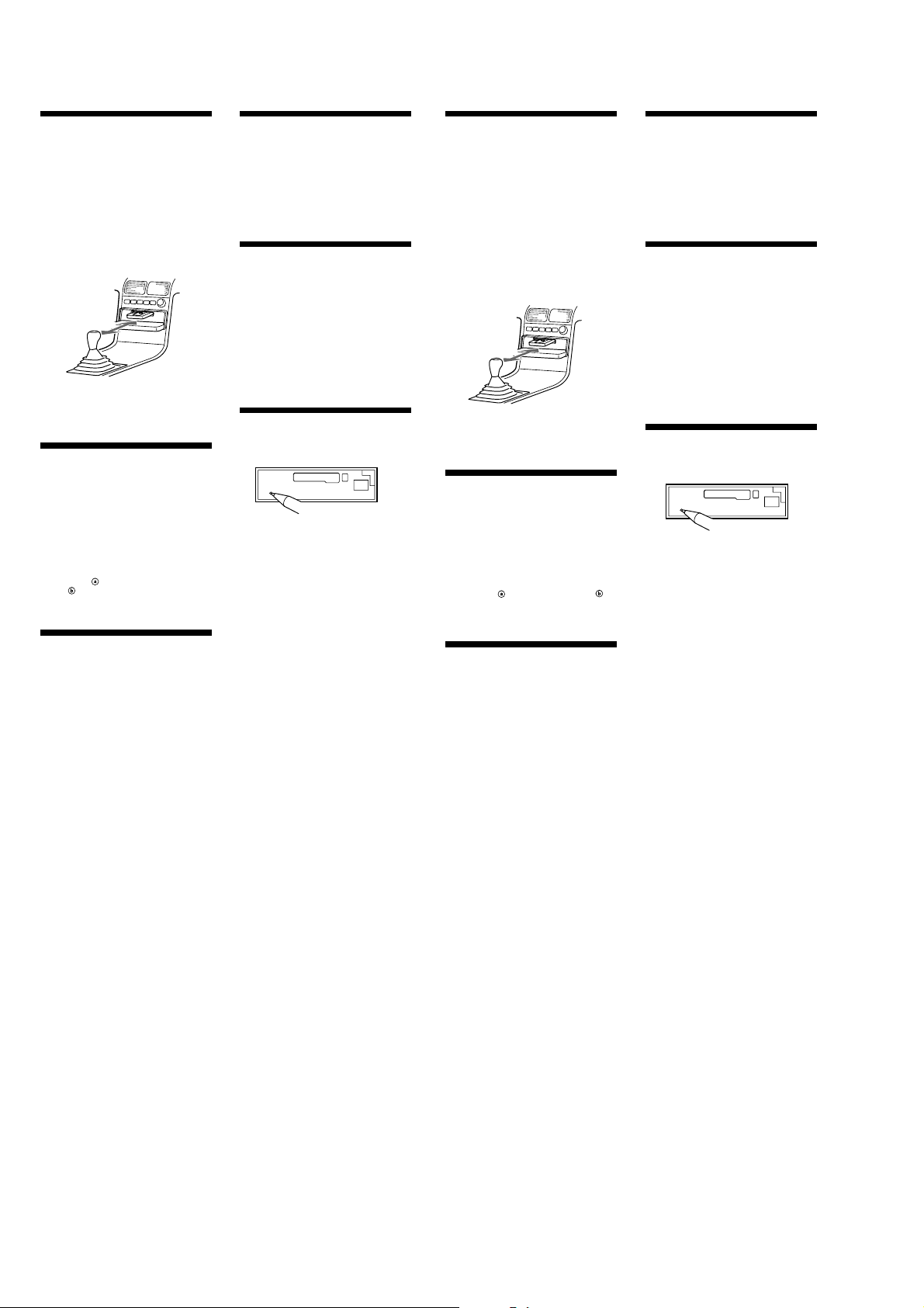
6 A
TOYOTA
max. size
5
5 × 8 mm
7
/32 × 11/32 in.)
(
Dimension
max. 5 × 8 mm
(7/32 × 11/32 po.)
2
Bend these claws
outward for a tight fit, if
necessary.
Plier ces griffes pour
assurer une prise
correcte si nécessaire.
to dashboard/center console
au tableau de bord/console centrale
Bracket
Support
Bracket
Support
Existing parts supplied with your car
Pièces existantes fournies avec la voiture
max. size
5
5 × 8 mm
7
(
/32 × 11/32 in.)
Dimension max.
5 × 8 mm
7
/32 × 11/32 po.)
(
3
5
6
6
B
5
6
NISSAN
max. size
5 × 8 mm
7
/32 × 11/32 in.)
(
Dimension
max. 5 × 8 mm
(7/32 × 11/32 po.)
5
Dashboard
4
Tableau de bord
7
5
Bracket
Support
Existing parts supplied with your car
Pièces existantes fournies avec la voiture
1
Fire wall
Paroi ignifuge
to dashboard/center console
au tableau de bord/console centrale
5
Bracket
Support
2
3
4
max. size
5 × 8 mm
7
/32 × 11/32 in.)
(
Dimension max.
5 × 8 mm
(7/32 × 11/32 po.)
7
XR-CA610X
Precautions
•Choose the installation location carefully so
that the unit will not interfere with normal
driving operations.
•Avoid installing the unit in areas subject to
dust, dirt, excessive vibration, or high
temperatures, such as in direct sunlight or near
heater ducts.
•Use only the supplied mounting hardware for
a safe and secure installation.
•There must be a distance of at least 15 cm
between the cassettes slot of the unit and shift
lever to insert cassette easily. Choose the
installation location carefully so the unit does
not interfere with gear shifting and other
driving operations.
15
cm
Mounting angle adjustment
Adjust the mounting angle to less than 20°.
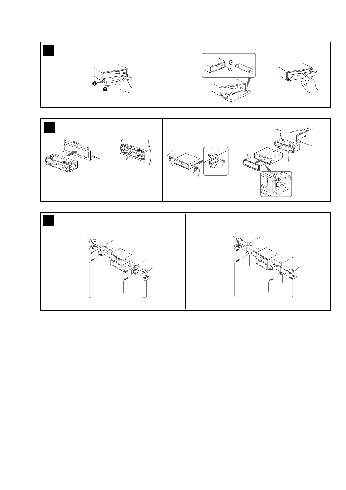
How to detach and attach the
front panel (4)
Before installing the unit, detach the front
panel.
4-A To detach
Before detaching the front panel, be sure to
press (OFF). Press (OPEN), then slide the front
panel to the right side, and pull out the left side.
4-B To attach
Place the hole
spindle
the left side in.
in the front panel onto the
on the unit as illustrated, then push
Mounting the unit in a Japanese
car (6)
You may not be able to install this unit in some
makes of Japanese cars. In such a case, consult
your Sony dealer.
Note
To prevent malfunction, install only with the
supplied screws 5.
Warning when installing in a car
without ACC (accessory)
position on the ignition key
switch
Be sure to press (OFF) on the unit for two
seconds to turn off the clock display after
turning off the engine.
When you press (OFF) only momentarily, the
clock display does not turn off and this causes
battery wear.
Reset button
When the installation and connections are
completed, be sure to press the reset button with
a ball-point pen, etc.
Précautions
•Choisissez soigneusement l’emplacement
d’installation pour que l’appareil ne gêne pas
le chauffeur pendant la conduite.
•Evitez d’installer l’appareil dans un endroit
exposé à la poussière, à la saleté, à des
vibrations excessives ou à des températures
élevées comme en plein soleil ou à proximité
de conduits de chauffage.
•Pour garantir un montage sûr, n’utilisez que le
matériel fourni.
•Pour pouvoir introduire et éjecter aisément la
cassette, il doit y avoir une distance d’au moins
15 cm entre le logement de la cassette de
l’appareil et le levier de changement de
vitesses. Choisissez l’endroit de montage de
telle façon que l’appareil ne gêne pas le
maniement du levier de changement de
vitesses ou toute autre opération de conduite.
15
cm
Réglage de l’angle de montage
Ajuster l’inclinaison à un angle inférieur à 20°.
Retrait et pose de la fa çade (4)
Avant d’installer l’appareil, retirez la façade.
4-A Pour retirer
Avant de retirer la façade, n’oubliez pas
d’appuyer d’abord sur (OFF). Appuyez sur
(OPEN), puis faites glisser la façade vers la
droite et retirez-la par la gauche
4-B Pour poser
Fixez la partie
l’appareil, comme indiqué sur l’illustration, puis
appuyez sur le côté gauche jusqu’au déclic.
de la façade sur la partie de
Installation de l ’appareil dans
une voiture japonaise (6)
Cet appareil ne peut pas être installé dans
certaines voitures japonaise. Consultez, dans ce
cas, votre concessionnaire Sony.
Remarque
Pour éviter tout dysfonctionnement, utilisez
uniquement les vis 5 pour le montage.
Avertissement en cas
d’installation dans une voiture
dont le contact ne comporte
pas de position ACC
(accessoires)
N’oubliez pas d’appuyer sur le bouton
(OFF) de l’appareil pendant deux
secondes après avoir coupé le moteur de
façon à désactiver l’affichage de l’horloge.
Si vous appuyez brièvement sur (OFF),
l’affichage de l’horloge n’est pas désactivé, ce
qui provoque une usure de la batterie.
Touche RESET
Quand l’installation et les raccordements sont
terminés, appuyez sur la touche RESET avec un
stylo à bille, etc.
Mounting example (5)
Installation in the dashboard
Exemple de montage (5)
Installation dans le tableau de bord
8
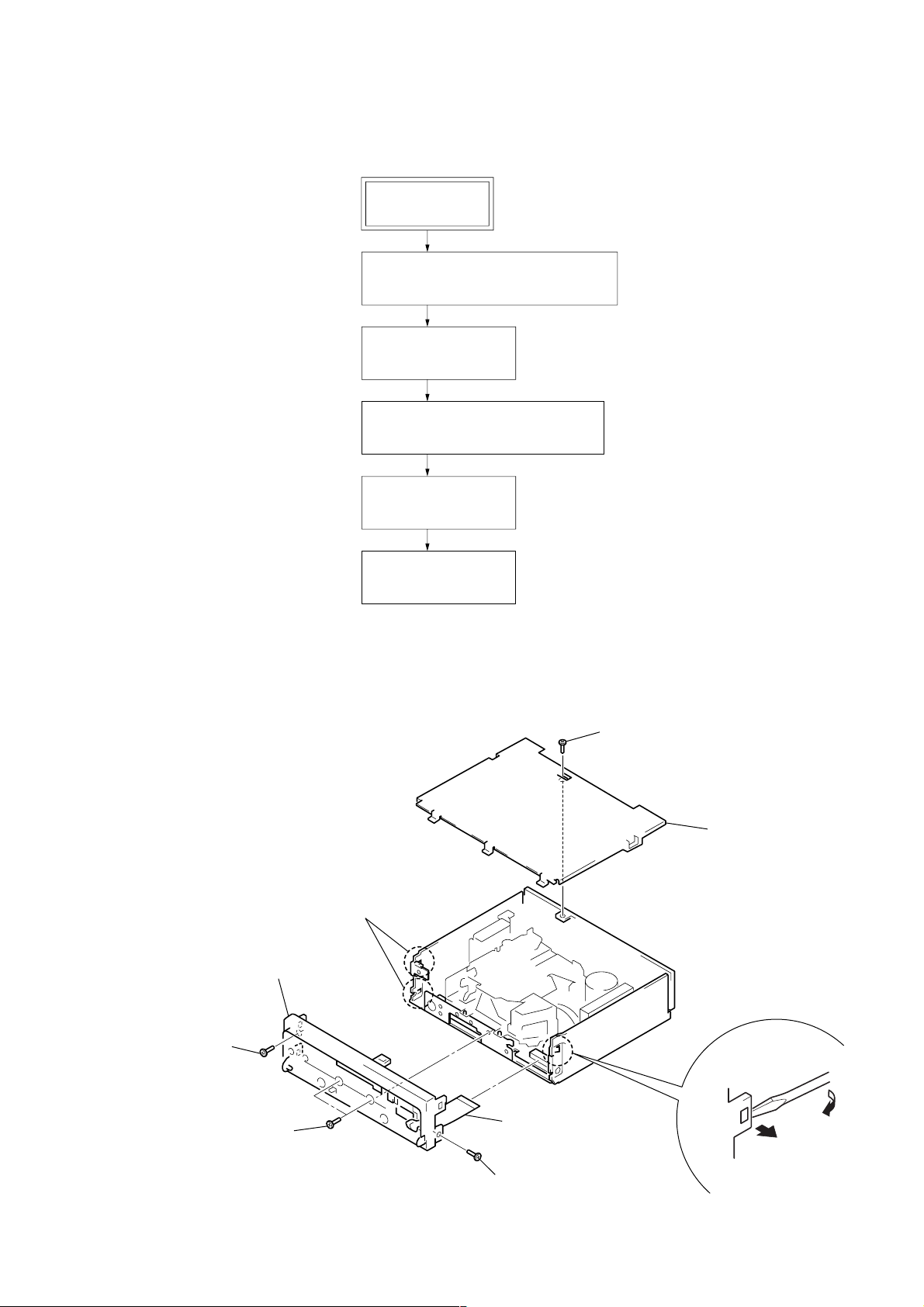
4
two claws
1
screw (PTT2.6 × 5)
2
cover
3
screw
(PTT2.6
×
6)
6
sub panel assy
3
two screws
(PTT2.6
×
6)
3
screw (PTT2.6 × 6)
5
flexible flat (14core) cable
(CN701)
4
claw
• This set can be disassembled in the order shown below.
2-1. DISASSEMBLY FLOW
FRONT PANEL SECTION
Note: Illustration of disassembly is omitted.
2-2. SUB PANEL ASSY
2-3. MECHANISM DECK (MG-25F-136)
XR-CA610X
SECTION 2
DISASSEMBLY
SET
(Page 9)
(Page 10)
2-4. MAIN BOARD
(Page 10)
2-5. HEAT SINK (2P)
(Page 11)
Note: Follow the disassembly procedure in the numerical order given.
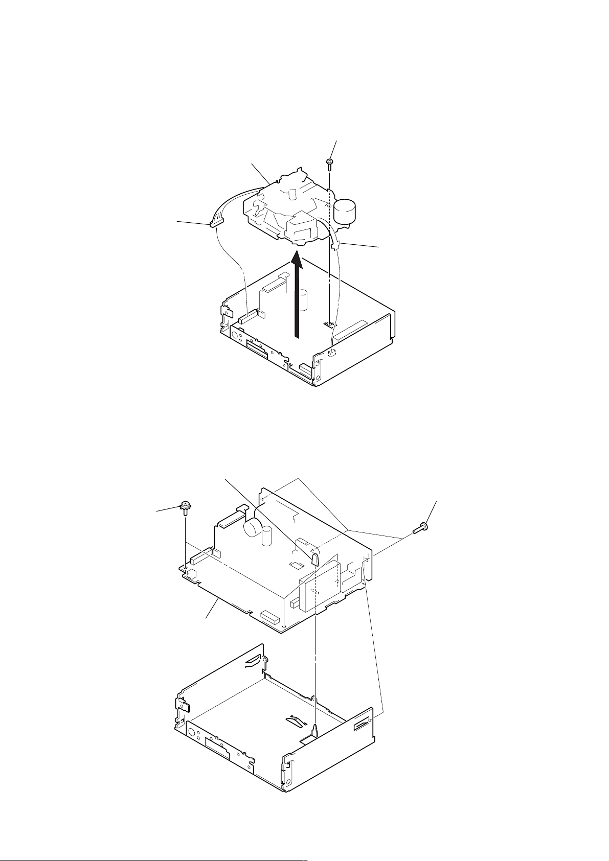
2-2. SUB PANEL ASSY
9
XR-CA610X
2-3. MECHANISM DECK (MG-25F-136)
4
mechanism deck (MG-25F-136)
2
connector
(CN351)
3
screw (PTT2.6 × 6)
1
flexible board
(CN301)
2-4. MAIN BOARD
2
three ground point
screws
4
main board
3
rubber cap (25)
1
three screws
(PTT2.6 × 8)
10
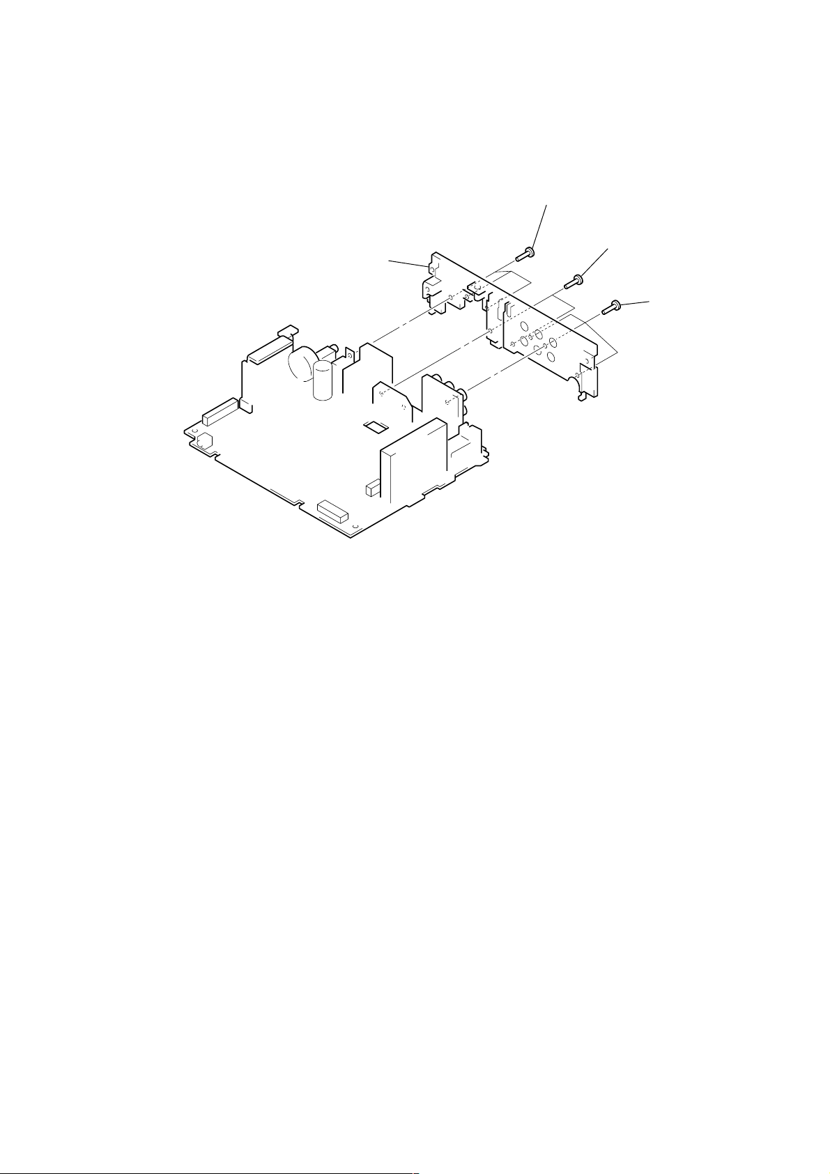
2-5. HEAT SINK (2P)
3
heat sink (2P)
1
three screws
(PTT2.6 × 8)
2
two screws
(PTT2.6 × 12)
XR-CA610X
1
three screws
(PTT2.6 × 8)
11
XR-CA610X
ASSEMBLY OF MECHANISM DECK
• This set can be assembled in the order shown below.
3-1. ASSEMBLY FLOW
3-2. HOUSING
(Page 12)
3-3. ARM (SUCTION)
(Page 13)
3-4. LEVER (LDG-A)/(LDG-B)
(Page 13)
3-5. GEAR (LDG-FT)
(Page 14)
3-6. GUIDE (C)
(Page 14)
SECTION 3
3-7. MOUNTING POSITION
OF CAPSTAN/REEL MOTOR (M901)
(Page 15)
Note: Follow the assembly procedure in the numerical order given.
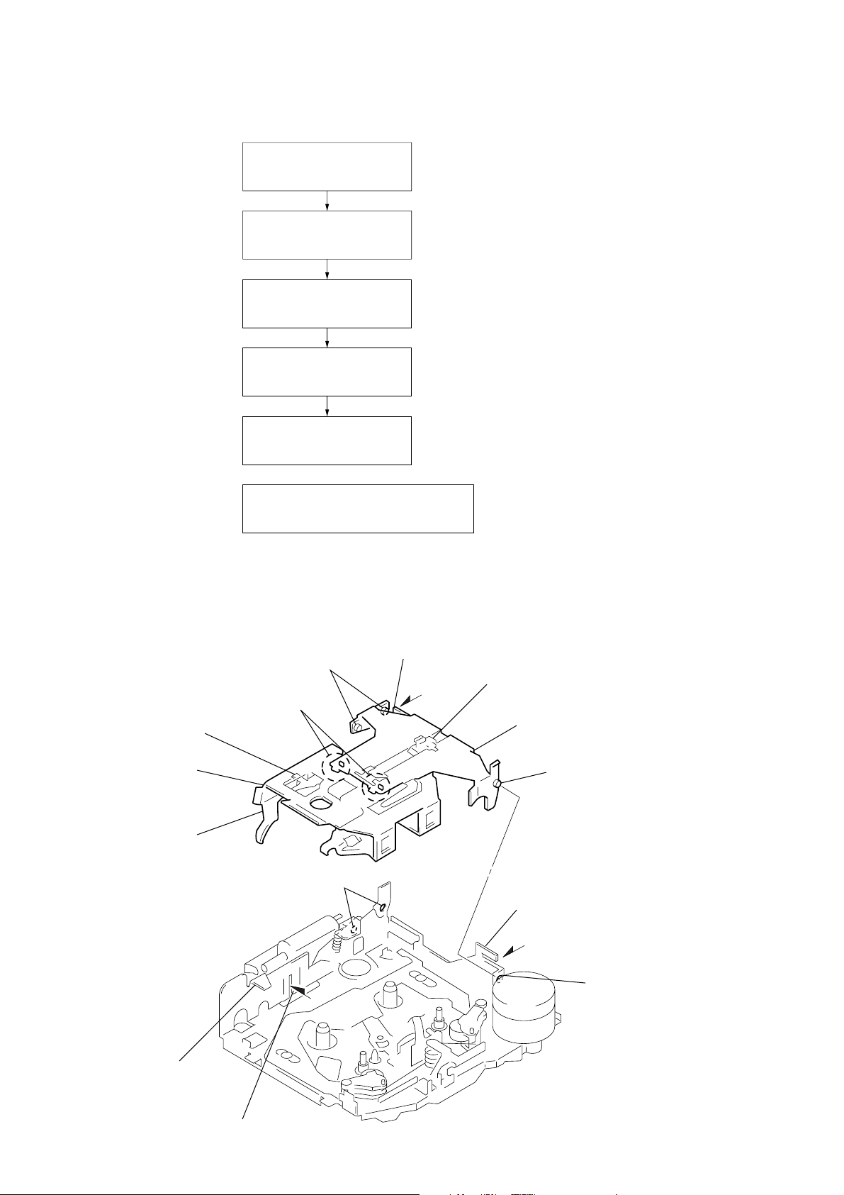
3-2. HOUSING
5 Fit projection on C part.
2 Install the hanger onto
two claws of the housing.
4 Fit claw on B part.
3 Put the housing
under A part.
housing
C part
7 Hold the hanger by bending the claw.
1 Install the catch to the hanger.
hanger
6 Fit projection on D part.
8 Hold the hanger by
bending the claw.
12
D part
A part
B part
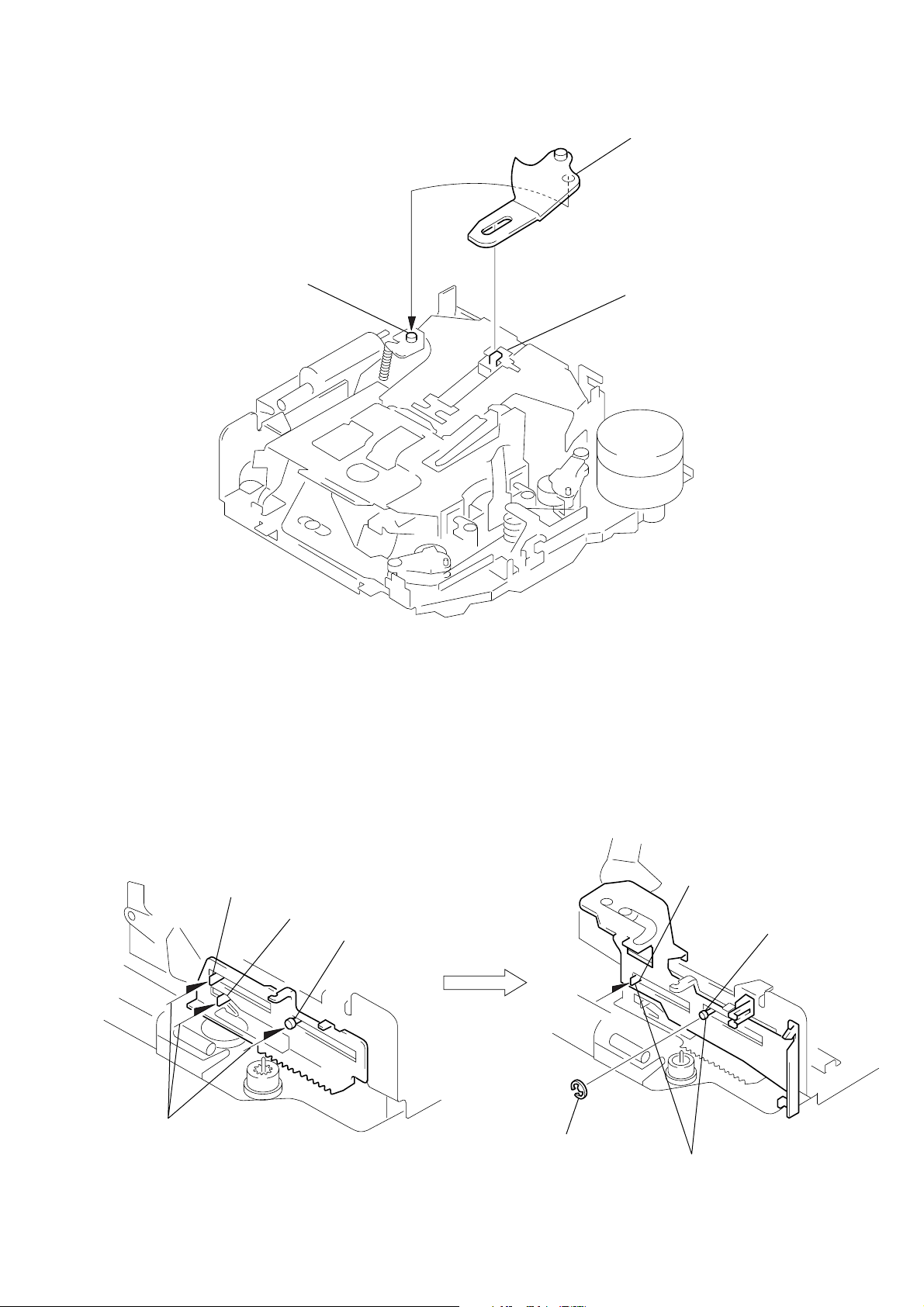
3-3. ARM (SUCTION)
2 Move the arm (suction) in the arrow
direction and fit on projection.
1 Fit the arm (suction) on the shaft.
projection
XR-CA610X
3-4. LEVER (LDG-A) / (LDG-B)
shaft A
shaft B
1 Fit the lever (LDG-A) on
shafts A – C and install it.
shaft C
shaft A
shaft B
3 type-E stop ring 2.0
2 Fit the lever (LDG-B) on
shafts A and B and
install it.
13
XR-CA610X
)
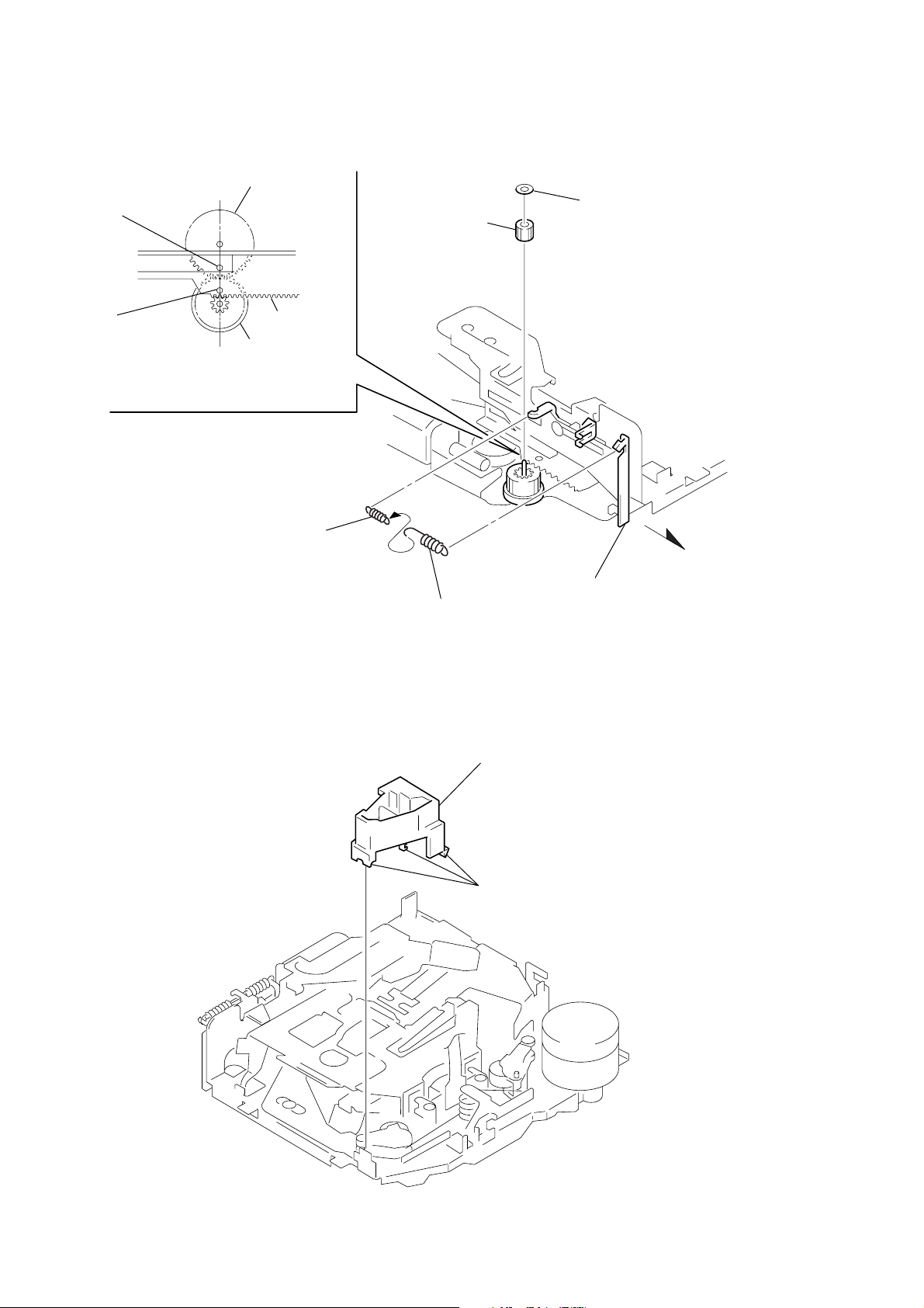
3-5. GEAR (LDG-FT)
hole
gear (LDG-D)
6 polyethylene washer
5 gear (LDG-FT)
hole
4 Align hole in the gear (LDG-D)
3-6. GUIDE (C)
lever (LDG-A)
gear (LDG-FB)
with hole the lever (LDG-A).
2 tension spring (LD-2)
1
2 tension spring (LD-1)
2 guide (C)
3 Move the lever (LDG-B
in the arrow direction.
14
1 three claws
 Loading...