

Sony XM-4060GTX User Manual
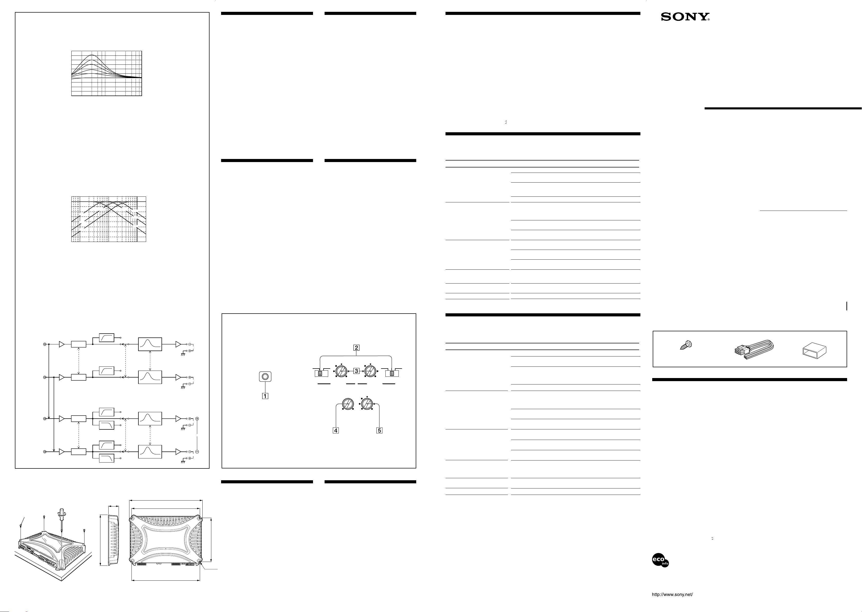
Low boost
Amplification de basses fréquences
dB
10
0
10
40 100 1k
Frequency/Fréquence Hz
Features
•Maximum power output of 120 W per channel (at 4
Ω).
•This unit can be used as a bridging amplifier with a
maximum output of 300 W.
•Direct connection can be made with the speaker
output of your car audio if it is not equipped with a
line output (High level input connection).
•Built-in variable LPF (Low-pass filter), HPF (Highpass filter) and low boost circuit.
•Protection circuit and indicator provided.
•Pulse power supply* for stable, regulated output
power.
* Pulse power supply
This unit has a built-in power regulator which
converts the power supplied by the DC 12 V car
battery into high speed pulses using a
semiconductor switch. These pulses are stepped up
by the built-in pulse transformer and separated into
both positive and negative power supplies before
being converted into direct current again. This light
weight power supply system provides a highly
efficient power supply with a low impedance
output.
Caractéristiques
•Puissance de sortie maximale de 120 W par
canal (à 4 W).
•Cet appareil peut être utilisé comme
amplificateur en pont d’une sortie maximale de
300 W.
•Une connexion directe est possible avec la sortie
haut-parleur de votre autoradio si celle-ci n’est
pas équipée d’une sortie de ligne (connexion
d’entrée haut niveau).
•Filtre passe-bas (LPF), filtre passe-haut (HPF)
variables et circuit d’amplification des graves
intégrés.
•Avec circuit et indicateur de protection.
•Alimentation électrique par impulsions* pour
une puissance de sortie stable, régulée.
* Alimentation électrique par impulsions
Cet appareil est équipé d’un régulateur de puissance
intégré qui convertit la puissance fournie par une
batterie de voiture de 12 V CC en impulsions ultrarapides au moyen d’un commutateur à semiconducteur. Ces impulsions sont amplifiées par le
transformateur d’impulsions intégré et séparées en
alimentation positive et négative avant d’être
reconverties en courant continu. Ce système
d’alimentation de faible poids assure une
alimentation électrique très efficace pour une sortie
d’impédance faible.
Spécifications
Circuiterie Circuit OTL (Sortie sans
Entrées Prises à broche RCA
Sorties Bornes de haut-parleurs
Impédance appropriée pour les enceintes
Sorties maximales Quatre haut-parleurs :
Sorties nominales (tension d’alimentation de 14,4 V)
Réponse en fréquence
transformateur)
Alimentation par impulsions
Connecteur d’entrée haut niveau
2 – 8 Ω (stéréo)
4 – 8 Ω (utilisé comme
amplificateur en pont)
120 W × 4 (à 4 Ω)
150 W × 4 (à 2 Ω)
Trois haut-parleurs :
120 W × 2 + 300 W × 1 (à 4 Ω)
Quatre haut-parleurs :
60 W × 4 (20 Hz – 20 kHz, 0,08 %
THD, à 4 Ω)
75 W × 4 (20 Hz – 20 kHz, 0,1 %
THD, à 2 Ω)
Trois haut-parleurs :
60 W × 2 + 150 W × 1 (20 Hz – 20
kHz, 0,1 % THD, à 4 Ω)
5 Hz – 50 kHz ( dB)
Distorsion harmonique
Plage de réglage du niveau d’entrée
Filtre passe-haut 50 – 300 Hz, –12 dB/oct
Filtre passe-bas 50 – 300 Hz, –12 dB/oct
Amplification de basses fréquences
Alimentation Batterie de voiture, courant continu
Tension d’alimentation
Courant à la sortie nominale : 31 A (4 Ω)
Dimensions Env. 400 × 55 × 276 mm
Poids Env. 4,6 kg (10 liv 3 on) accessoires
Accessoires fournis Vis de montage (4)
La conception et les spécifications peuvent être modifiées
sans préavis.
0,005 % ou inférieure (à 1 kHz)
0,3 – 6,0 V (prises à broche RCA)
1,2 – 12 V (entrée haut niveau)
0 – 10 dB (40 Hz)
12 V (masse négative)
10,5 – 16 V
Entrée de télécommande : 1 mA
(l/h/p) (15
parties saillantes et commandes
non comprises
non compris
Cordon d’entrée haut niveau (1)
Cache de protection (1)
3
/4 × 2 1/4 × 10 7/8 po)
Troubleshooting Guide
The following checklist will assist in the correction of most problems which you may encounter with your unit.
Before going through the checklist below, refer to the connection and operating procedures.
3-263-557-11 (2)
Stereo Power
Amplifier
Operating Instructions
Mode d’emploi
Cut-off frequency
Fréquence de coupure
dB
10
0
-10
-20
-30
-40
-50
-60
-70
-80
HIGH PASS
50Hz
170Hz
300Hz
10 100 1k
Frequency/Fréquence Hz
LOW PASS
300Hz
170Hz
50Hz
Location and Function of
Controls
1 POWER/PROTECTOR indicator
Lights up in green during operation.
When the PROTECTOR is activated the
indicator will change from green to red.
When the PROTECTOR is activated refer to
the TroubleShooting Guide.
2 FILTER selector switch
When the switch is in the LPF position, the
filter is set to low-pass. When in the HPF
position, the filter is set to high-pass.
3 Cut-off frequency adjustment control
Sets the cut-off frequency (50 – 300 Hz) for the
low-pass or high-pass filters.
4 LOW BOOST level control
Turn this control to boost the frequencies
around 40 Hz to a maximum of 10 dB.
5 LEVEL adjustment control
The input level can be adjusted with this
control. Turn it in the clockwise direction
when the output level of the car audio seems
low.
Emplacement et
fonction des commandes
1 Indicateur POWER/PROTECTOR
S’allume en vert en cours de fonctionnement.
Lorsque PROTECTOR est activé, le voyant
passe du vert au rouge.
Lorsque PROTECTOR est activé, reportezvous au guide de dépannage.
2 Commutateur de sélection FILTER
Lorsque le commutateur de sélection est en
position LPF, le filtre est réglé sur passe-bas.
Lorsqu’il est en position HPF, le filtre est réglé
sur passe-haut.
3 Commandes de réglage de la fréquence de
coupure
Règle la fréquence de coupure (50 – 300 Hz)
des filtres passe-bas ou passe-haut.
4 Commande de niveau LOW BOOST
Tournez cette commande pour amplifier les
fréquences autour de 40 Hz jusqu’à un
maximum de 10 dB.
5 Commande de réglage LEVEL
Le niveau d’entrée peut être réglé avec cette
commande. Tournez cette commande dans le
sens des aiguilles d’une montre lorsque le
niveau de sortie de l’autoradio semble faible.
Problem
The POWER/PROTECTOR indicator
does not light up.
• The POWER/PROTECTOR indicator
will change from green to red.
• The unit becomes abnormally hot.
Alternator noise is heard.
The sound is muffled.
The sound is too low.
The sound is interrupted.
Cause/Solution
The fuse is blown. t Replace both the fuses with a new one.
The ground wire is not securely connected.
t Fasten the ground wire securely to a metal point of the car.
The voltage going into the remote terminal is too low.
• The connected master unit is not turned on. t Turn on the master unit.
• The system employs too many amplifiers. t Use a relay.
Check the battery voltage (10.5 – 16 V).
Turn off the power switch. The speaker outputs are short-circuited.
t Rectify the cause of the short-circuit.
• Use speakers with suitable impedance.
t 2 – 8 Ω (stereo) , 4 – 8 Ω (when used as a bridging amplifier).
Turn off the power switch. Make sure the speaker cord and ground wire are
securely connected.
The unit heats up abnormally.
• Make sure to place the unit in a well ventilated location.
The power connecting wires are installed too close to the RCA pin cords.
t Keep the power connecting wires away from the RCA pin cords.
The ground wire is not securely connected.
t Fasten the ground wire securely to a metal point of the car.
Negative speaker cords are touching the car chassis.
t Keep the cords away from the car chassis.
The FILTER switch is set to the “LPF” position.
• By default, the FILTER switch is in “OFF” position.
t When connecting the full range speaker, set to the “OFF” position.
The LEVEL adjustment control is not appropriate. Turn the LEVEL adjustment
control in the clockwise direction.
The thermal protector is activated. t Reduce the volume.
Owner’s Record
The model and serial numbers are located on the bottom of the unit.
Record the serial number in the space provided below.
Refer to these numbers whenever you call upon your Sony dealer regarding this product.
Model No. XM-4060GTX Serial No.
XM-4060GTX
2004 Sony Corporation Printed in Korea
Circuit Diagram
Schéma du circuit
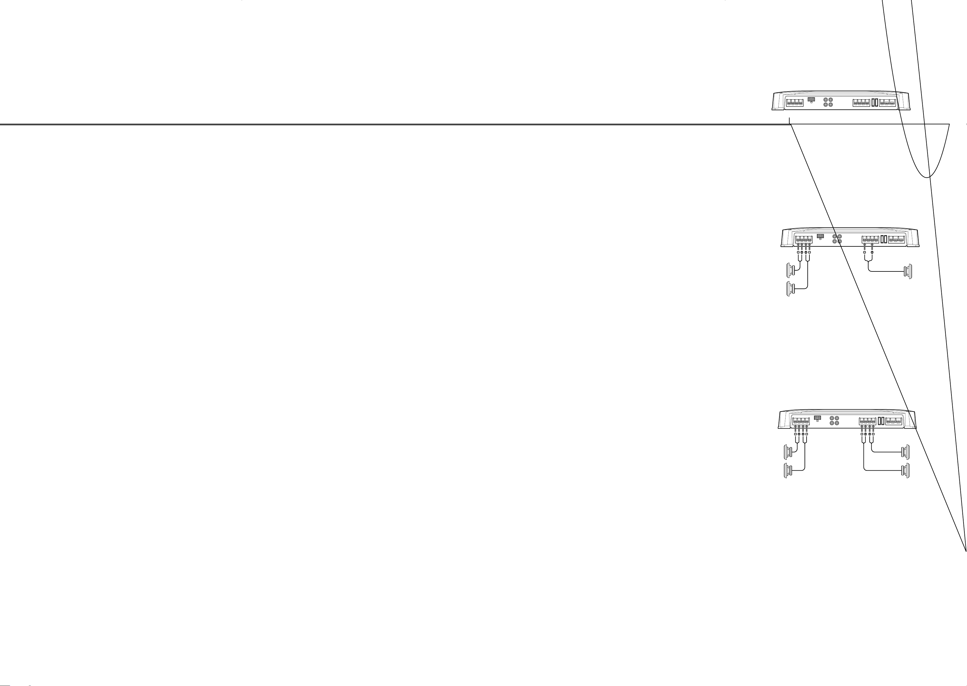
Front:
Avant :
Rear:
Arrière :
1
Lch
Rch
Lch
Rch
LEVEL
LEVEL
Normal
LEVEL
Inverted
LEVEL
FILTER
HPF
OFF
FILTER
HPF
OFF
FILTER
HPF
OFF
LPF
FILTER
HPF
OFF
LPF
Unit : mm (in.)
Unité : mm (po)
55
1
(2
/4 )
)
8
/
7
276 (10
LOW BOOST
LOW BOOST
LOW BOOST
LOW BOOST
400 (15 3/4)
5
370 (14
373 (14 3/4)
Parts for Installation and Connections
Guide de dépannage
La liste suivante vous aidera à résoudre la plupart des problèmes que vous pouvez rencontrer avec cet
Power
AMP
Lch
FILTER
Power
AMP
Rch
Power
AMP
Lch
BTL.
Power
AMP
Rch
Installation
Before Installation
/8)
•Mount the unit either inside the trunk or under a
seat.
POWER/PROTECTOR
Installation
Avant l’installation
•Installez l’appareil dans le coffre ou sous un siège.
•Choisissez avec soin l’emplacement de sorte que
•Choose the mounting location carefully so the unit
will not interfere with the normal movements of the
driver and it will not be exposed to direct sunlight
)
8
/
3
237 (9
ø 6 (1/4)
or hot air from the heater.
•Do not install the unit under the floor carpet, where
the heat dissipation from the unit will be
considerably impaired.
First, place the unit where you plan to install it, and
mark the positions of the four screw holes on the
surface of the mounting board (not supplied). Then
drill the holes approximately 3 mm (
1
/8 in.) in
diameter and mount the unit onto the board with the
supplied mounting screws. The supplied mounting
screws are 15 mm (19/32 in.) long. Therefore, make
sure that the mounting board is thicker than 15 mm
•N’installez pas l’appareil sous le tapis de sol car la
Présentez d’abord l’appareil à l’endroit où vous
voulez l’installer et tracez un rep0ère de
positionnement pour les quatre vis sur la plaque de
montage (non fournie). Percez des trous d’environ 3
mm (
plaque de montage à l’aide des vis fournies. Celles-ci
font 15 mm (
conséquent, que la plaque fait de plus de 15 mm (
po) d’épaisseur.
170
110
60
50 300Hz
LOW BOOST
(40Hz)
0 +10dB
l’appareil ne gêne pas les mouvements du
conducteur et qu’il ne soit pas exposé au soleil ou à
l’air chaud du chauffage.
dissipation thermique ne pourrait pas se faire
correctement.
1
/8 po) de diamètre, puis fixez l’appareil sur la
110
60
260
LEVEL
4
5.5
60.3V
19
/32 po) de long. Vérifiez, par
FILTER
170
260
50 300Hz
REARFRONT
2
0.5
LPF OFF HPFOFF HPF
19
/32
(19/32 in.).
appareil. Avant de passer la liste en revue, vérifiez les procédures de raccordement et d’utilisation.
Problème
L’indicateur POWER/PROTECTOR ne
s’allume pas.
• L’indicateur POWER/PROTECTOR
passe du vert au rouge.
• L’appareil chauffe de façon
anormale.
L’alternateur émet un bruit.
Le son est étouffé.
Le son est trop faible.
Le son est interrompu.
Cause/Solution
Le fusible est grillé. t Remplacez les deux fusibles par des neufs.
Le fil de masse n’est pas connecté correctement.
t Fixez correctement le fil de masse à un point métallique de la voiture.
La tension entrant sur la borne de télécommande est trop faible.
• L’appareil maître connecté n’est pas allumé.
t Mettez l’appareil maître sous tension.
• Le système utilise trop d’amplificateurs. t Utilisez un relais.
Vérifiez la tension de la batterie (10,5 – 16 V).
Coupez l’interrupteur d’alimentation. Les sorties de haut-parleur sont courtcircuitées. t Remédiez à la cause du court-circuit.
• Utilisez des haut-parleurs d’une impédance appropriée.
t 2 – 8 Ω (stéréo) , 4 – 8 Ω (utilisé comme amplificateur en pont).
Coupez l’interrupteur d’alimentation. Assurez-vous que le cordon de hautparleur et le fil de masse sont correctement branchés.
L’appareil chauffe anormalement.
• Installez l’appareil dans un endroit bien aéré.
Les câbles d’alimentation sont installés trop près des câbles à broches RCA.
t Eloignez les câbles d’alimentation des broches RCA.
Le fil de masse n’est pas connecté correctement.
t Fixez correctement le fil de masse à un point métallique de la voiture.
Les fils négatifs des haut-parleurs touchent la carrosserie de la voiture.
t Eloignez les fils de la carrosserie de la voiture.
Le commutateur FILTER est réglé sur la position « LPF ».
• Le réglage par défaut du commutateur FILTER est « OFF ».
t Lors du raccordement du haut-parleur à gamme étendue, réglez ce
commutateur sur « OFF ».
La commande de réglage de LEVEL est mal réglée. Tournez la commande de
réglage LEVEL dans le sens des aiguilles d’une montre.
Le protecteur thermique est activé. t Réduisez le volume.
Pièces destinées à l’installation et aux raccordements
12
ø 5 × 15
(× 4)
0.2 m
3
Specifications
AUDIO POWER SPECIFICATIONS
POWER OUTPUT AND TOTAL HARMONIC DISTORTION
60 watts per channel minimum continuous average power into 4 ohms,
both channels driven from 20 Hz to 20 kHz with no more than 0.08 %
total harmonic distortion per Car Audio Ad Hoc Committee standards.
Other Specifications
Circuit system OTL (output transformerless)
Inputs RCA pin jacks
Outputs Speaker terminals
Suitable speaker impedance
Maximum outputs Four speakers:
Rated outputs (supply voltage at 14.4 V)
Frequency response 5 Hz – 50 kHz (
• Lead-free solder is used for soldering certain parts.
• Halogenated flame retardants are not used in printed wiring boards.
• Halogenated flame retardants are not used in cabinets.
• Corrugated cardboard is used for the packaging cushions.
circuit
Pulse power supply
High level input connector
2 – 8 Ω (stereo)
4 – 8 Ω (when used as a bridging
amplifier)
120 W × 4 (at 4 Ω)
150 W × 4 (at 2 Ω)
Three speakers:
120 W × 2 + 300 W × 1 (at 4 Ω)
Four speakers:
60 W × 4 (20 Hz – 20 kHz, 0.08 %
THD, at 4 Ω)
75 W × 4 (20 Hz – 20 kHz, 0.1 %
THD, at 2 Ω)
Three speakers:
60 W × 2 + 150 W × 1 (20 Hz – 20
kHz, 0.1 % THD, at 4 Ω)
dB)
Harmonic distortion 0.005 % or less (at 1 kHz)
Input level adjustment range
High-pass filter 50 – 300 Hz, –12 dB/oct
Low-pass filter 50 – 300 Hz, –12 dB/oct
Low boost 0 – 10 dB (40 Hz)
Power requirements 12 V DC car battery
Power supply voltage
Current drain at rated output: 31 A (4 Ω)
Dimensions Approx. 400 × 55 × 276 mm
Mass Approx. 4.6 kg (10 lb. 3 oz.) not
Supplied accessories Mounting screws (4)
Design and specifications are subject to change without
notice.
0.3 – 6.0 V (RCA pin jacks)
1.2 – 12 V (High level input)
(negative ground)
10.5 – 16 V
Remote input: 1 mA
3
(w/h/d) (15
not incl. projecting parts and
controls
incl. accessories
High level input cord (1)
Protection cap (1)
/4 × 2 1/4 × 10 7/8 in.)
 Loading...