

Sony XM-2000-R Service manual
XM-2000R
SERVICE MANUAL
Photo: AEP model
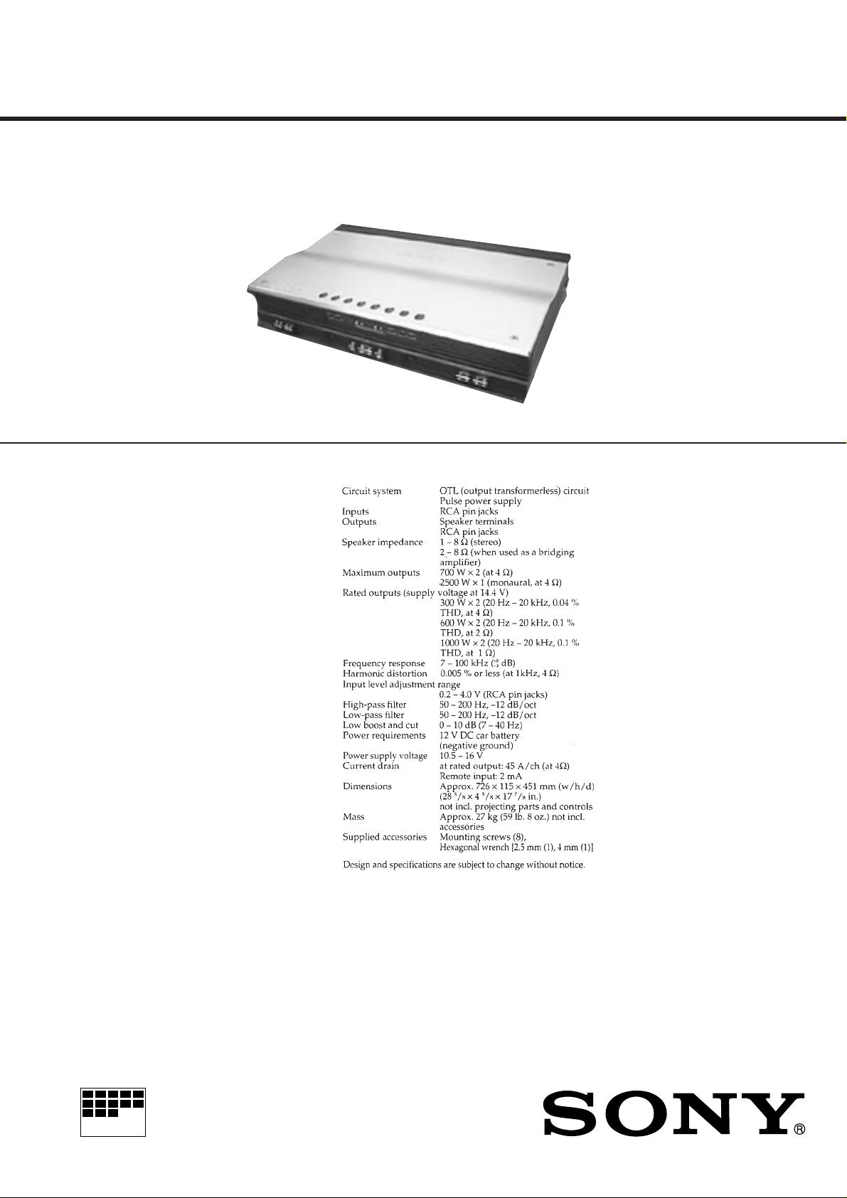
SPECIFICATIONS
US Model
Canadian Model
AEP Model
UK Model
MICROFILM
STEREO POWER AMPLIFIER

TABLE OF CONTENTS
1. SERVICING NOTES ................................................ 3
2. GENERAL ................................................................... 4
3. DISASSEMBLY ......................................................... 8
4. ELECTRICAL ADJUSTMENTS......................... 9
5. DIAGRAMS
5-1. Note for Printed Wiring Boards and
Schematic Diagrams ....................................................... 12
5-2. Printed Wiring Board – PRE AMP Section –................ 13
5-3. Schematic Diagram – PRE AMP Section –.................... 15
5-4. Printed Wiring Boards – PROTECT Section – ............. 17
5-5. Schematic Diagram – PROTECT Section –.................. 19
5-6. Printed Wiring Boards
– POWER AMP Section (Component Side) – .............. 21
5-7. Printed Wiring Boards
– POWER AMP Section (Conductor Side) – ................ 23
5-8. Schematic Diagram – POWER AMP Section – ............ 25
6. EXPLODED VIEWS ................................................ 28
7. ELECTRICAL PARTS LIST ............................... 32
Notes on chip component replacement
• Never reuse a disconnected chip component.
• Notice that the minus side of a tantalum capacitor may be damaged by heat.
– 2 –

SECTION 1
+
+
C867
C871
T851
JW81
PROTECT OFF
(disconnect)
– PROTECT Board –
(Component Side)
SERVICING NOTES
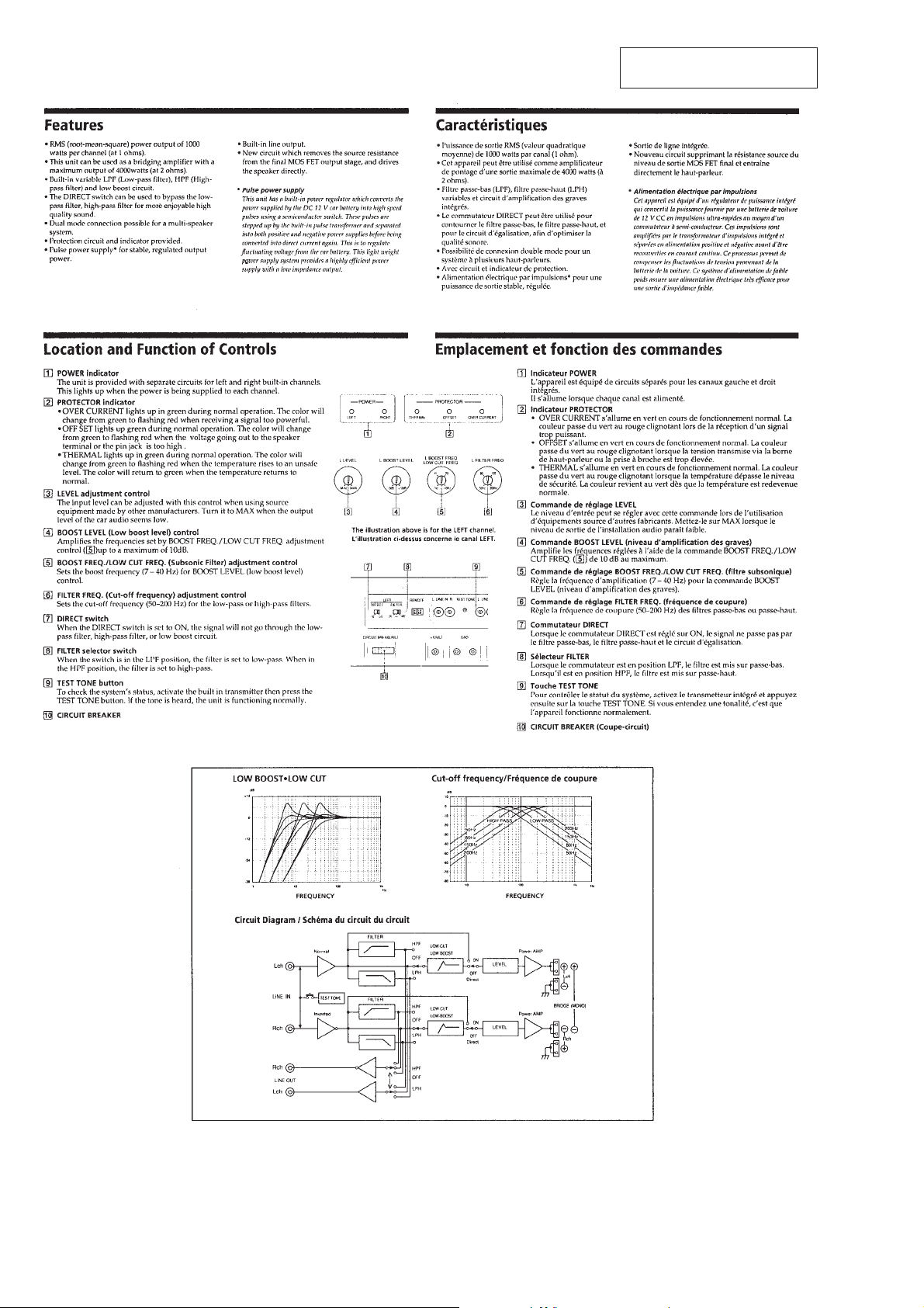
PROTECTOR
This set has protection circuit and indicators. When trouble occurs, LED indicates status.
Each LED lights up in green during normal operation. The color
will change green to flashing red when trouble occurred.
*1: Does not work in no-signal condition.
TEST TONE
To check the system’s status, activate the built in transmitter then
press the [TESTTONE] button (S801). If the tone is heard, the set
is functioning normally.
CANCELLING THE PROTECTOR AT THE SERVICE
Note: When check the protector, do not cancel it.
In case of a failure in this set, the protection circuit functions to
prevent a speaker damage and turn off the power to stop the set
working.
To make the set work at the service, disconnect the JW81 of the
PROTECT board and turn on the power.
Be sure to reconnect the JW81, after the completion of service.
LED
OFFSET (D851)
OVER CURRENT *1
(D852)
THERMAL (D855)
Problem
• DC voltages are applied to the
SPEAKER OUT terminal (CN812,
CN813)
• DC voltages out to the SPEAKER
OUT terminal cause the internal circuit troubled
• The SPEAKER OUT terminal is
shorted
• The internal output element is troubled
• The temperature rises to unsafe level
Solution
Turn off the power switch. Make sure the speaker cord and
ground lead are securely connect
Turn off the power switch. Make sure the SPEAKER OUT
terminal are not short-circuited
The set heats up abnormally
• Stereo operation: 1 to 8 Ω
• Bridging operation: 2 to 8 Ω
Make sure to place the set in a ventilated location
(The color will return to green when the temperature returns
to normal)
– 3 –
SECTION 2
GENERAL
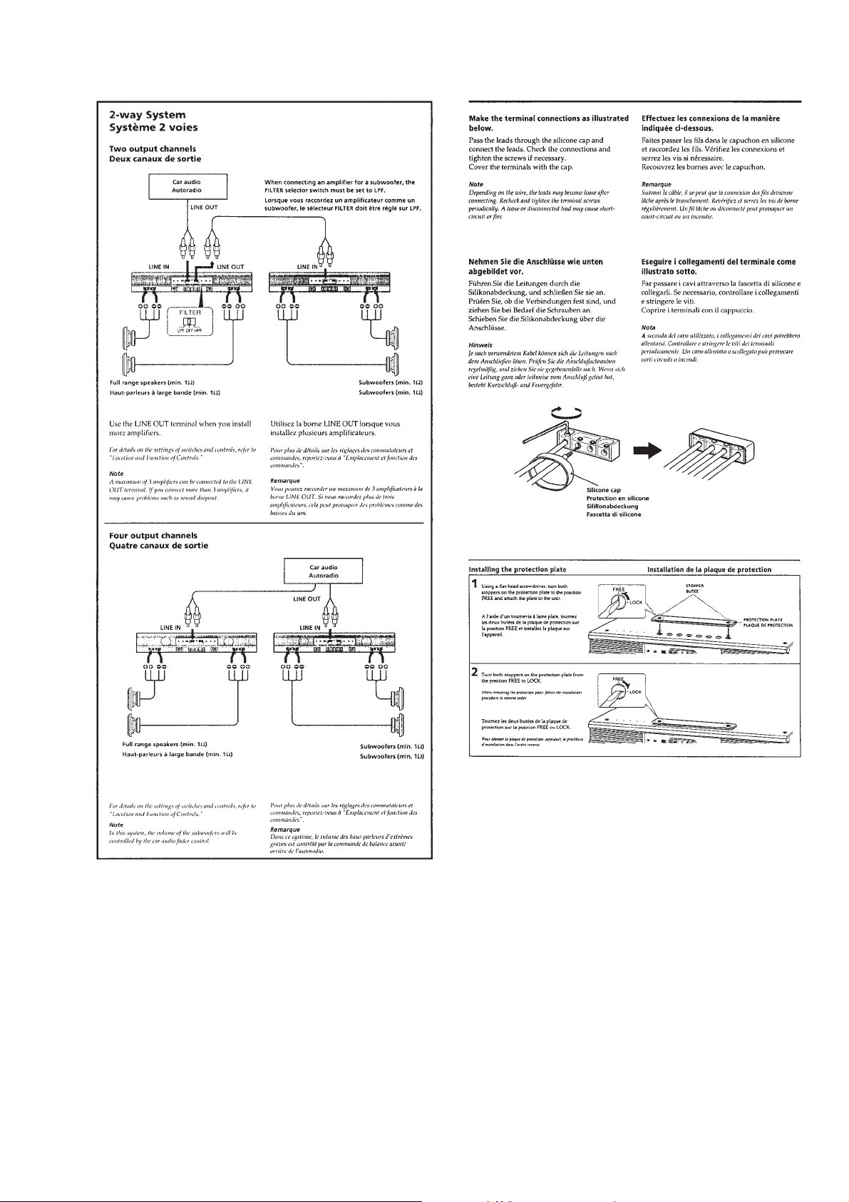
This section is extracted from
instruction manual.
– 4 –
– 5 –
– 6 –
– 7 –
(US, Canadian Model)
SECTION 3
s
d
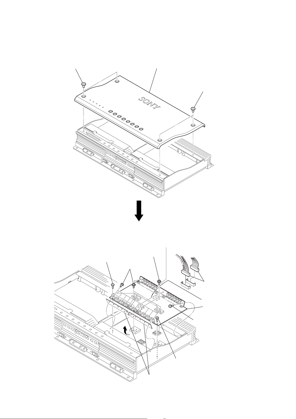
DISASSEMBLY
Note: Follow the disassembly procedure in the numerical order given.
TOP PLATE
1
two ornamental screws
2
top plate
1
two ornamental screw
POWER AMP BOARD
5
two screws
(M 4
4
eight screws
(M 4
×
×
10)
6)
1
two connectors
(CNP805, 808)
6
2
5
screw
×
6)
(M 4
POWER AMP boar
three screws
(BVTP 3
×
10)
×
6)
3
sixteen screws
(PSW 3
– 8 –
7
two sheets (B)

SECTION 4
r
ELECTRICAL ADJUSTMENTS
IDLING ADJUSTMENT (without signal input)
Note: The idling adjustment should be executed on the L-CH and R-CH
of the POWER AMP board respectively.
Connection:
Digital voltmete
POWER AMP board (L-CH or R-CH)
TP1
TP2
Procedure:
1. Connect the digital voltmeter to TP1 and TP2 on the POWER
AMP board.
2. Turn fully the VR901 counterclockwise. (*1)
3. Turn on the power.
4. T urn the VR901 (*2) so that a reading on the digital voltmeter
is in a range of 1mV to 3mV in the center of 2mV. (*3)
5. In the same manner, adjust another POWER AMP board.
*1: This prevents over current from flowing. If over current flows, the
protector works to disable the amplifier.
*2: The idling current increases when VR901 is turned clockwise, or
decreases by counterclockwise turn.
*3: The voltage will fluctuate sensitively, thus requiring careful
adjustment.
Adjustment Location: See page 10 .
+
–
PROTECTOR CHECK
Note 1: Check it without canceling the protector.
Note 2: The protector check should be executed on the L-CH and R-CH
of the POWER AMP board respectively.
1. Offset Protector Check
Procedure:
1. Turn on the power, and short the SPEAKER OUT terminal
(CN812 or CN813) and +12V terminal (CN814) on the
POWER AMP board.
2. The protector will work, then confirm that the OFFSET LED
(D851) color changes lighting green to flashing red and the
output is turned off.
3. Open the SPEAKER OUT terminal and +12V terminal.
4. Confirm that the protector is not reset.
5. Turn off the power once, and turn it on again, then confirm
that the protector does not work.
Checking Location: See page 10 .
2. Over Current Protector Check
Procedure:
1. Turn on the power, and short TP2 and TP3 on the POWER
AMP board.
2. The protector will work, then confirm that the OVER CURRENT LED (D852) color changes lighting green to flashing
red and the output is turned off.
3. Open the TP2 and TP3.
4. Confirm that the protector is not reset.
5. Turn off the power once, and turn it on again, then confirm
that the protector does not work.
Checking Location: See page 10 .
3. Thermal Protector Check
Procedure:
1. Turn on the power, and short TP4 and TP5 on the POWER
AMP board.
2. The protector will work, then confirm that the THERMAL LED
(D855) color changes lighting green to flashing red, the fun
motor (M810 or M811) rotates, and the output is turned off.
3. Open the TP4 and TP5.
4. Confirm that the protector is reset.
Checking Location: See page 10 .
– 9 –
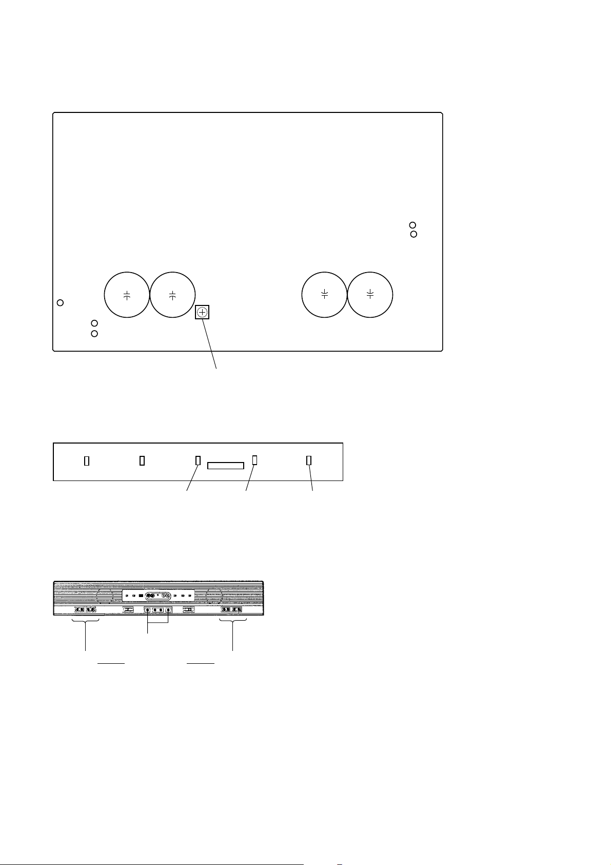
Adjustment Location and Checking Location :
– POWER AMP Board (L-CH or R-CH) (Component Side) –
TP5
TP4
C919
TP3
TP2
TP1
C920
++
– LED Board (Conductor Side) –
D854 D853
D855
THERMAL
VR901 Idling Adjustment
CNB807
D851
OFFSET
OVER CURRENT
C917 C916
++
D852
– FRONT VIEW –
CN814 +12V (L/R) terminals
CN813
LEFT
SPEAKER OUT
terminals
CN812
RIGHT
– 10 –
 Loading...