

Sony XL70U Service Manual
XL-70/70C
SERVICE MANUAL
No. S5037XL-70///
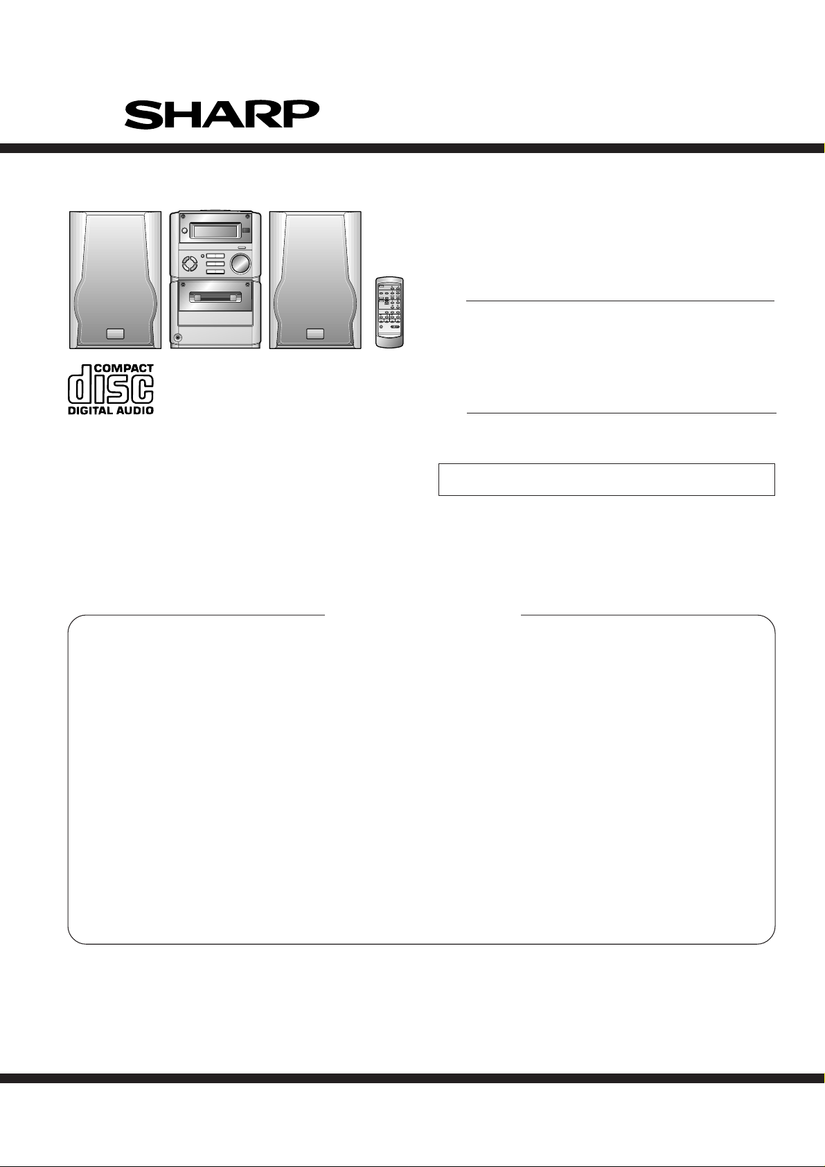
MICRO COMPONENT SYSTEM
MODEL
XL-70 Micro Component System consisting of XL-70 (main unit) and
CP-XL70U (speaker system).
MODEL
XL-70C Micro Component System consisting of XL-70C (main unit)
and CP-XL70U (speaker system).
• In the interests of user-safety the set should be restored to its original
condition and only parts identical to those specified should be used.
XL-70
XL-70C
CONTENTS
Page
IMPORTANT SERVICE NOTES (FOR U.S.A. ONLY)...................................................................................................... 2
SPECIFICATIONS ............................................................................................................................................................ 2
NAMES OF PARTS .......................................................................................................................................................... 3
OPERATION MANUAL..................................................................................................................................................... 5
DISASSEMBLY................................................................................................................................................................. 8
REMOVING AND REINSTALLING THE MAIN PARTS.................................................................................................. 10
ADJUSTMENT................................................................................................................................................................ 12
TEST MODE ................................................................................................................................................................... 13
ERROR LIST .................................................................................................................................................................. 17
NOTES ON SCHEMATIC DIAGRAM ............................................................................................................................. 18
TYPES OF TRANSISTOR AND LED.............................................................................................................................. 18
WAVEFORMS OF CD CIRCUIT..................................................................................................................................... 19
BLOCK DIAGRAM .......................................................................................................................................................... 20
SCHEMATIC DIAGRAM ................................................................................................................................................. 24
WIRING SIDE OF P.W.BOARD...................................................................................................................................... 30
TROUBLESHOOTING .................................................................................................................................................... 34
FUNCTION TABLE OF IC .............................................................................................................................................. 40
LCD SEGMENT .............................................................................................................................................................. 48
PARTS GUIDE/EXPLODED VIEW
PACKING OF THE SET (FOR U.S.A. ONLY)
SHARP CORPORATION
This document has been published to be used
for after sales service only.
The contents are subject to change without notice.
XL-70/70C
FOR A COMPLETE DESCRIPTION OF THE OPERATION OF THIS UNIT, PLEASE REFER
TO THE OPERATION MANUAL.
IMPORT ANT SER VICE NOTES (FOR U.S.A. ONLY)
BEFORE RETURNING THE AUDIO PRODUCT
(Fire & Shock Hazard)
Before returning the audio product to the user, perform the
following safety checks.
1. Inspect all lead dress to make certain that leads are not
pinched or that hardware is not lodged between the chassis
and other metal parts in the audio product.
2. Inspect all protective devices such as insulating materials,
cabinet, terminal board, adjustment and compartment covers
or shields, mechanical insulators etc.
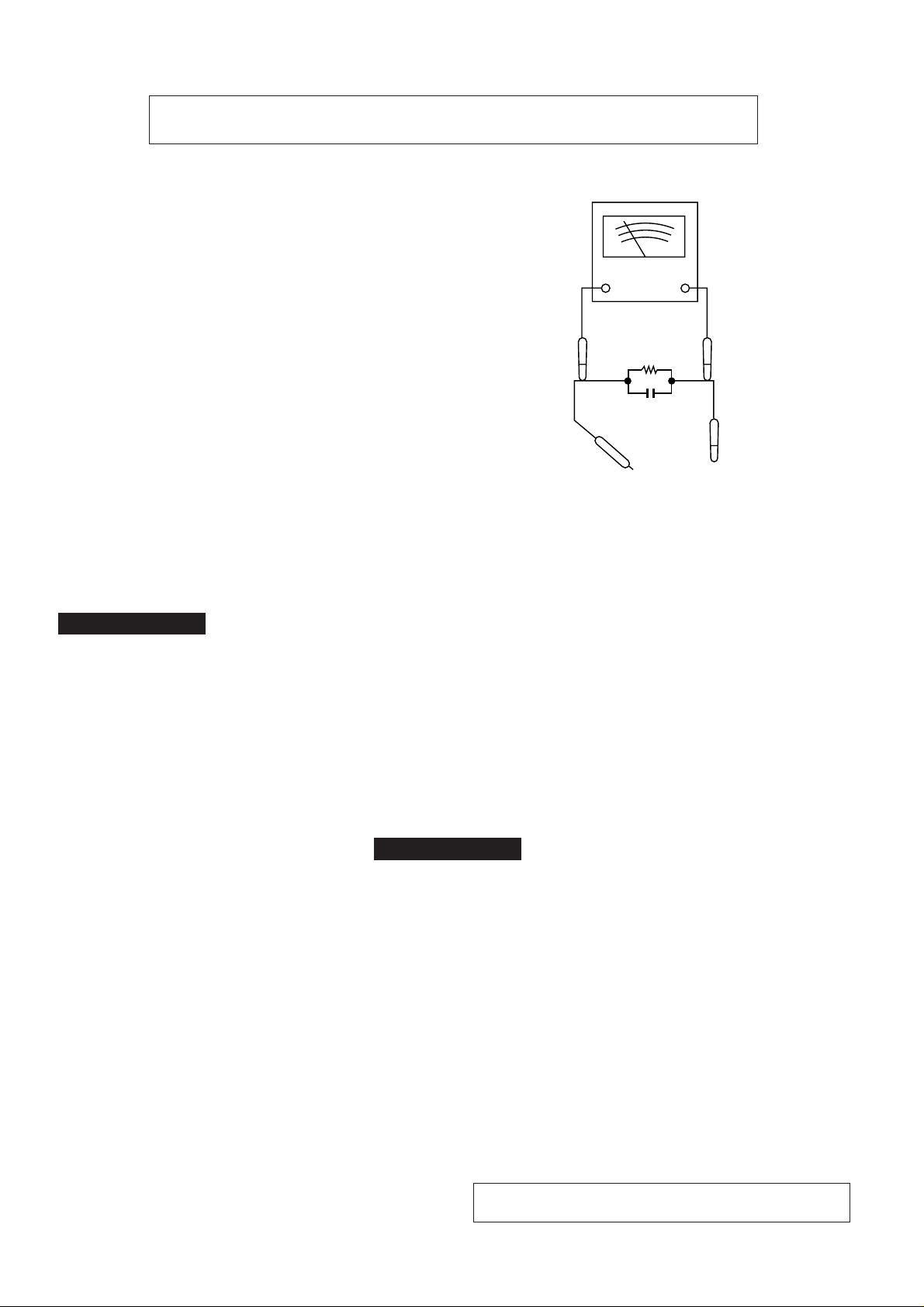
3. To be sure that no shock hazard exists, check for leakage
current in the following manner.
* Plug the AC line cord directly into a 120 volt AC outlet.
* Using two clip leads, connect a 1.5k ohm, 10 watt resistor
paralleled by a 0.15µF capacitor in series with all exposed
metal cabinet parts and a known earth ground, such as
conduit or electrical ground connected to earth ground.
* Use a VTVM or VOM with 1000 ohm per volt, or higher,
sensitivity to measure the AC voltage drop across the
resistor (See diagram).
* Connect the resistor connection to all exposed metal parts
having a return path to the chassis (antenna, metal cabinet,
screw heads, knobs and control shafts, escutcheon, etc.)
and measure the AC voltage drop across the resistor.
VTVM
AC SCALE
1.5k ohms
10W
0.15µF
TEST PROBE
TO EXPOSED
METAL PARTS
CONNECT TO
KNOWN EARTH
GROUND
All check must be repeated with the AC line cord plug connection
reversed.
Any reading of 0.3 volt RMS (this corresponds to 0.2 milliamp.
AC.) or more is excessive and indicates a potential shock
hazard which must be corrected before returning the audio
product to the owner.
XL-70/70C
● General
Power source: AC 120 V, 60 Hz
Power
consumption: 48 W
Dimensions: Width; 6-5/16" (160 mm)
Height; 9-1/2" (241 mm)
Depth; 11-3/4" (298 mm)
Weight: 7.9 lbs.(3.6 kg)
● Amplifier section
Output power: 16 watts minimum RMS per
channel into 4 ohms from
100 Hz to 20 kHz, 10% total
harmonic distortion
Output terminals: Speakers; 4 ohms
Headphones; 16-50 ohms
(recommended; 32 ohms)
CD digital output (optical)
Sub woofer (audio signal);
500 mV/47 k ohms
Input terminals: Video/Auxiliary (audio signal);
500 mV/47 k ohms
● Compact disc player section
Type: Compact disc player
Signal readout: Non-contact, 3-beam semi-
conductor laser pickup
D/A converter: 1-bit D/A converter
Filter: 8-times oversampling digital
filter
Frequency
response: 20 - 20,000 Hz
Wow and flutter: Unmeasurable
(less than 0.001% W. peak)
SPECIFICATIONS
● Tuner section
Frequency range: FM; 87.5-108 MHz
AM; 530-1,720 kHz
● Cassette deck section
Frequency
response: 50 - 14,000 Hz (Normal tape)
Signal/noise ratio: 50 dB
Wow and flutter: 0.25 % (WRMS)
CP-XL70U
Type: 2-way [4" (10 cm) woofer and
1" (2.5 cm) tweeter]
Rated input
power: 20 W
Maximum input
power: 40 W
Impedance: 4 ohms
Dimensions: Width; 6-5/16" (160 mm)
Height; 9-1/2" (240 mm)
Depth; 7-7/16" (189 mm)
Weight: 5.1 lbs.(2.3 kg)/each
Specifications for this model are subject to change without
prior notice.
– 2 –
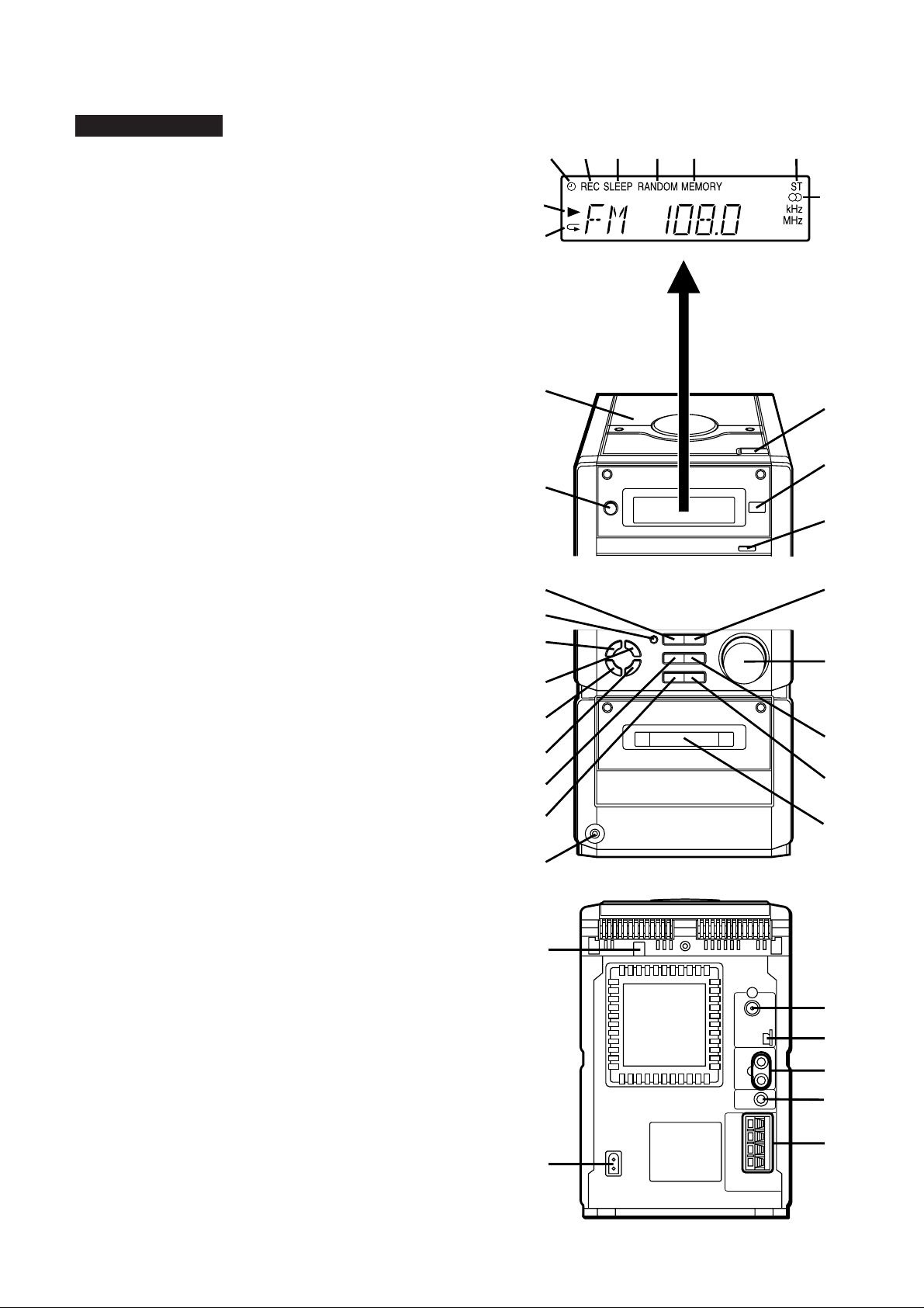
■ Front panel
10
11
12
13
14
15
16
17
18
24
25
26
27
28
19
20
21
22
23
1
2
3
4
5
6
9
8
7
1
2
3
4
5
7
6
1. Timer Indicator
2. Record Indicator
3. Sleep Indicator
4. (CD) Random Indicator
5. (CD/TUNER) Memory Indicator
6. FM Stereo Mode Indicator
7. FM Stereo Indicator
8. (CD) Play Indicator
9. (CD) Repeat Indicator
10. CD Compartment
11. Power Button
12. CD Open/Close Button
13. Remote Control Sensor
14. Volume Select Button
XL-70/70C
XL-70/70C
NAMES OF PARTS
15. (CD/TAPE) Stop Button
(TUNER) Memory Clear Button
16. Record Pause Button
17. Bass/Treble Selector Button
18. Memory/Set Button
19. Clock/Timer/Sleep Button
20. Band Selector Button
21. (CD) Review Button
(TAPE) Rewind Button
(TUNER) Tuning Down Button
22. Function Selector Button
23. Headphone Socket
24. (CD) Play/Pause Button
(TAPE) Play Button
25. Jog Dial
26. (CD) Cue Button
(TAPE) Fast Forward Button
(TUNER) Tuning Up Button
27. Volume/Jog Dial Selector Button
28. Cassette Compartment
■ Rear panel
1. CD Digital Output Jack
2. AC Power Input Jack
3. FM 75 Ohms Antenna Jack
4. AM Loop Antenna Input Jack
5. Video/Auxiliary (Audio Signal) Input Jacks
6. Sub Woofer Output Jack
7. Speaker Terminals
– 3 –
XL-70/70C
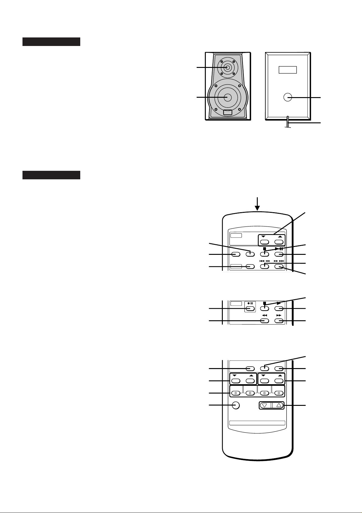
CP-XL70U
1. Tweeter
2. Woofer
3. Bass Reflex Duct
4. Speaker Wire
1
XL-70/70C
■ Remote control
1. Remote Control Transmitter LED
● Tuner control section
2. Preset Up/Down Buttons
● CD control section
3. Clear Button
4. Random/Repeat Button
5. Memory Button
6. Stop Button
7. Play/Pause Button
8. Track Down/Review Button
9. Track Up/Cue Button
2
3
4
5
10
3
4
1
2
6
7
8
9
12
13
● Tape control section
10. Record Pause Button
11. Rewind Button
12. Stop Button
13. Play Button
14. Fast Forward Button
● Common section
15. Sleep Button
16. Bass Up/Down Buttons
17. Function Selector Buttons
18. Power Button
19. Timer Button
20. Clock Button
21. Treble Up/Down Buttons
22. Volume Up/Down Buttons
– 4 –
11
15
16
17
18
14
19
20
21
22
OPERATION MANUAL
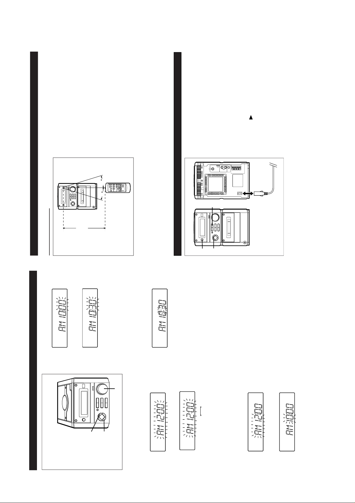
RESETTING THE MICROCOMPUTER
1
3
2,3
AC INPUT
3
Reset the microcomputer under the following
conditions:
● T o erase all of the stored memory contents (clock
and timer settings, and tuner and CD presets).
● If the display is not correct.
● If the operation is not correct.
1
Press the POWER button to enter the stand-by
mode.2Unplug the AC power cord from the AC INPUT
jack on this unit.
3
Whilst pressing down the MEMORY/SET but-
ton and the button, plug the AC power cord
into the AC INPUT jack on this unit.
Caution:
● The operation explained above will erase all data
stored in memory, such as clock and timer set-
tings, and tuner and CD presets.
15
15
Notes concerning use:
● Replace the batteries if the operating distance is
reduced or if the operation becomes erratic.
● Periodically clean the transmitter LED on the re-
mote control and the sensor on the main unit
with a soft cloth.
● Exposing the sensor on the main unit to strong
light may interfere with operation. Change the
lighting or the direction of the unit.
● Keep the remote control away from moisture,
excessive heat, shock, and vibrations.
■ Remote control
PREPARATION FOR USE
8” - 20”
(0.2 m - 6 m)
SETTING THE CLOCK
1
Press the CLOCK/TIMER/SLEEP button to en-
ter the time check mode.
2
Within 3 seconds, press the MEMORY/SET
button.3Turn the jog dial to select the time display mode.
AM 12:00 0:00
“AM 12:00” → The 12-hour display will appear.
(AM 12:00 - PM 11:59)
“0:00” → The 24-hour display will appear.
(0:00 - 23:59)
● Note that this can only be set when the unit is
first installed or it has been reset.
4
Press the MEMORY/SET button.
5
Adjust the hour by turning the jog dial.
● When the jog dial is turned one click clockwise,
the time will increase by 1 hour. When it is turned
one click counterclockwise, the time will de-
crease by 1 hour.
Keep turning the jog dial to change the time con-
tinuously.
● When the 12-hour display is selected, “AM” will
change automatically to “PM”.
● In this example, the clock is set for the
12-hour (AM 12:00) system.
CLOCK/TIMER/
SLEEP
MEMORY/SET
Jog dial
6
Press the MEMORY/SET button.
7
Adjust the minutes by turning the jog dial.
● When the jog dial is turned one click clockwise,
the time will increase by 1 minute. When it is
turned one click counterclockwise, the time will
decrease by 1 minute.
Keep turning the jog dial to change the time con-
tinuously.
● The hour setting will not advance even if min-
utes advance from “59” to “00”.
8
Press the MEMORY/SET button.
● The clock starts operating from “0” second. (Sec-
onds are not displayed.)
Note:
● In the event of a power failure or when the AC
power cord is disconnected, the clock display will
go out.
When the AC power supply is restored, the clock
display will flash on and off to indicate the time
when the power failure occurred or when the AC
power cord was disconnected.
If this happens, follow the procedure below to
change the clock time.
To change the clock time:
Perform steps 1, 2 and 4 - 8 above.
To change the time display mode:
1
Perform steps 1 - 3 in the section “RESETTING
THE MICROCOMPUTER”.
2
Perform steps 1 - 8 above.
XL-70/70C
– 5 –
XL-70/70C
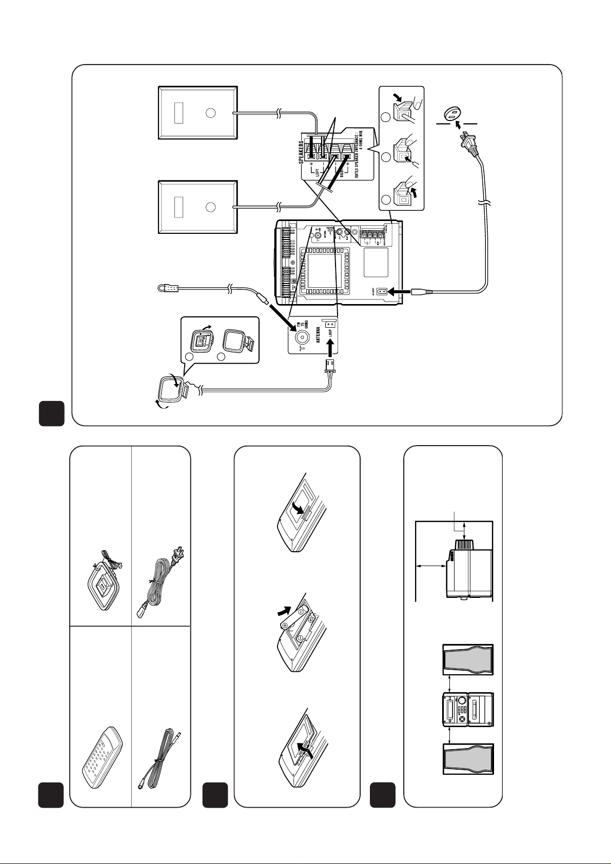
Placing the system
Instalación del sistema
4"(10 cm)
4"(10 cm)
8"(20 cm)
4"(10 cm)
3
2
Putting batteries into the remote control
Inserción de las pilas en el controlador remoto
1
Remove the battery cover.
Extraiga la cubierta de las
pilas.
1
Check the supplied accessories
Compruebe los accesorios suministrados
FM antenna × 1
Antena de FM
×
1
Remote control × 1
Controlador remoto
×
1
AC power cord × 1
Cable de alimentación
de CA
×
1
AM loop antenna ×1
Antena de cuadro de
AM
×
1
2
Insert the batteries.
Inserte las pilas.
3
Replace the battery cover.
Vuelva a colocar la cubierta.
2 “AA” size batteries (UM/SUM-3, R6, HP-7 or similar)
2 pilas del tamaño “AA” (UM/SUM-3, R6, HP-7 or similares)
Batteries are not included.
Las pilas no están incluidas.
4
Connections
Conexiones
1
2
2
1
3
SUB
WOOFER
OUT
1
Connect the AM and FM antennas.
Conecte las antenas de AM y FM.
2
Connect the speaker system.
Conecte el sistema de altavoces.
FM antenna
Antena de FM
AM loop antenna
Antena de cuadro de AM
AC 120 V, 60 Hz
120 V de CA, 60 Hz
3
Connect the AC power cord.
Conecte el cable de alimentación de CA.
White line
Línea blanca
Right speaker
Altavoz derecho
Left speaker
Altavoz izquierdo
– 6 –
XL-70/70C
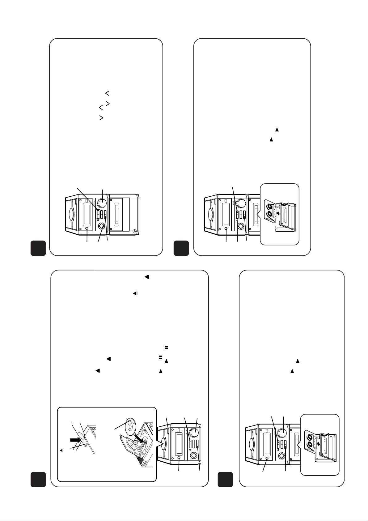
6
Listening to a tape
Audición de una cinta
1
2
5
3
4
1
2
6
4
3
OPEN/CLOSE
Label side up
7
5
Con el lado de la etiqueta
hacia arriba
1
Press the POWER button to turn the power on.
Pulse el botón POWER para conectar la alimentación.
2
Press the FUNCTION button until “CD” or “NO DISC” ap-
pears.
Pulse el botón FUNCTION hasta que aparezca “CD” o
“NO DISC”.
3
Press the OPEN/CLOSE button to open the CD com-
partment.
Pulse el botón OPEN/CLOSE para abrir el comparti-
miento del CD.
4
Place a CD on the spindle.
Ponga un disco compacto en el eje.
5
Close the CD compartment by pushing the OPEN/
CLOSE button.
Cierre el compartimiento del CD pulsando el botón
OPEN/CLOSE.
6
Press the /CD button.
Pulse el botón /CD .
7
Adjust the VOLUME control.
Ajuste el control VOLUME.
5
Listening to a CD
Audición de un disco CD
1
Press the POWER button to turn the power on.
Pulse el botón POWER para conectar la alimentación.
2
Press the FUNCTION button until “TAPE” appears.
Pulse el botón FUNCTION hasta que aparezca “TAPE”.
3
Load a cassette.
Inserte un cassette.
4
Press the button.
Pulse el botón .
5
Adjust the VOLUME control.
Ajuste el control VOLUME.
8
Recording from a CD
Grabación de un disco CD
1
Press the POWER button to turn the power on.
Pulse el botón POWER para conectar la alimentación.
2 Press the FUNCTION button until “CD” or “NO DISC” ap-
pears.
Pulse el botón FUNCTION hasta que aparezca “CD” o
“NO DISC”.
3
Load a CD and a recordable cassette.
Inserte un disco compacto y un cassette grabable.
4 Press the REC PAUSE button.
Pulse el botón REC PAUSE.
5 Press the button.
Pulse el botón .
1
2
5
4
3
1
2
3
4
5
1 Press the POWER button to turn the power on.
Pulse el botón POWER para conectar la alimentación.
2 Press the FUNCTION button until “FM” or “AM” appears.
Pulse el botón FUNCTION hasta que “FM” o “AM” aparezca.
3 Press the BAND button to select FM ST, FM or AM.
Pulse el botón BAND para seleccionar FM ST, FM o AM.
4 Press the TUNING ( or ) button to tune into a station.
Pulse el botón TUNing ( o ) para sintonizar una
emisora.
5
Adjust the VOLUME control.
Ajuste el control VOLUME.
Listening to the radio
Audición de la radio
7
– 7 –
(A1)x2
ø3x10mm
(B2)x1
(C1)x2
ø3x10mm
Side Panel (Right)
Front
Panel
RearPanel
(C1)x1
ø3x10mm
Side Panel
(Lift)
(B2)x1
(A1)x4
ø3x10mm
(A1)x1
ø3x10mm
(A1)x1
ø3x10mm
(B1)x1
ø3x10mm
Top Cabinet
CD PWB
Display
PWB
Main PWB
(C2)x2
ø3x8mm
XL-70/70C
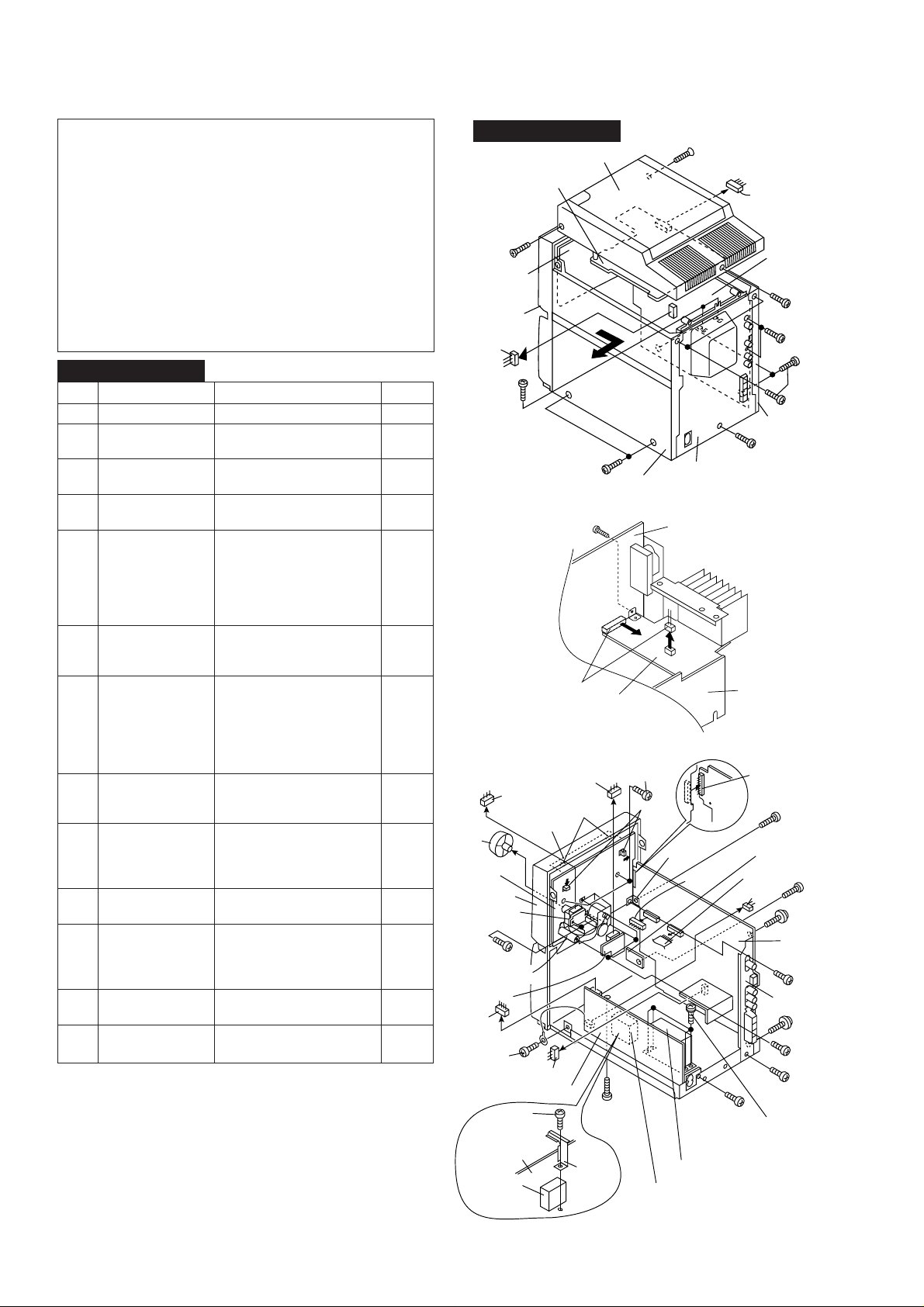
DISASSEMBLY
Caution on Disassembly
Follow the below-mentioned notes when disassembling
the unit and reassembling it, to keep it safe and ensure
excellent performance:
1. Take cassette tape and compact disc out of the unit.
2. Be sure to remove the power supply plug from the wall
outlet before starting to disassemble the unit.
3. Take off nylon bands or wire holders where they need to
be removed when disassembling the unit. After servicing
the unit, be sure to rearrange the leads where they were
before disassembling.
4. Take sufficient care on static electricity of integrated
circuits and other circuits when servicing.
XL-70/70C
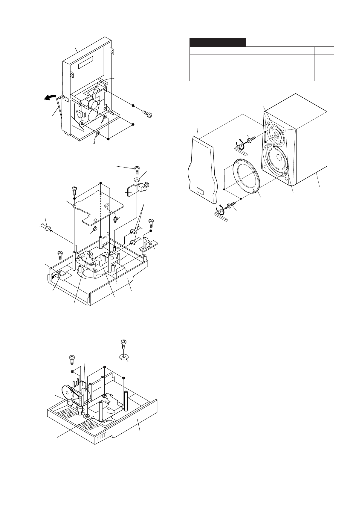
STEP REMOVAL
1 Side Panel
(Left/Right)
2 Top Cabinet 1. Screw .................. (B1) x1 8-1
3 Rear Panel 1. Screw .................. (C1) x3 8-1
4 Power Amp. PWB 1. Screw .................. (D1) x1 8-2
5 Main PWB/ 1. Screw .................. (E1) x3 8-3
Headphones PWB 2. Screw .................. (E2) x2
6 Jog Switch PWB 1. Socket ................. (F1) x1 8-3
7 Display PWB/ 1. Screw .................. (G1) x3 8-3
LED PWB 2. Screw .................. (G2) x3
(With Jog Motor 3. Bracket................ (G3) x1
Holder) 4. Socket ................. (G4) x1
8 Front Panel 1. Screw .................. (H1) x1 8-3
9 Power PWB 1. Screw .................. (J1) x4 8-3
10 Tape Mechanism 1. Open the cassette holder 9-1
11 CD PWB/ 1. Screw .................. (L1) x6 9-2
Open Close Switch 2. Socket ................. (L2) x4
PWB/CD Lid PWB 3. Hook .................... (L3) x1
(Note)
12 Digital Out PWB 1. Socket ................. (M1) x1 9-2
13 CD Mechanism 1. Screw .................. (N1) x3 9-3
Note:
After removing the connector for the optical pickup from the
connector, wrap the conductive aluminium foil around the
front end of connector remove to protect the optical pickup
from electrostatic damage.
PROCEDURE
FIGURE
1. Screw .................. (A1) x8 8-1
2. Socket ................. (B2) x2
2. Screw .................. (C2) x2
2. Socket ................. (D2) x2
3. Bracket ................ (E3) x1
4. Socket ................. (E4) x3
5. Flat wire............... (E5) x1
6. Socket ................. (E6) x1
2. Screw .................. (F2) x2
3. Knob .................... (F3) x1
5. Hook .................... (G5) x2
6. Hook .................... (G6) x2
2. Socket ................. (H2) x1
3. Screw .................. (H3) x1
2. Screw .................. (J2) x1
3. Screw .................. (J3) x1
4. Bracket ................ (J4) x1
2. Screw .................. (K1) x4
2. Screw .................. (M2) x1
2. Screw .................. (N2) x3
(F3)x1
Display PWB
Front Panel
Jog Switch
(F2)x2
ø2.5x12mm
Tape
Mechanism
PWB
(G4)x1
Sub Power
Transformer
– 8 –
XL-70/70C
(F1)x1
PWB
Jog Motor
Holder
(H3)x1
ø3x6mm
Power PWB
(J3)x1
ø3x6mm
Power PWB
(D1)x1
ø3x8mm
LED PWB
(E4)x1
(D2)x2
(E4)x1
(G6)x2
(J4)x1
Figure 8-1
Power Amp.
PWB
Figure 8-2
(G2)x2
ø2.5x10mm
(G5)x2
(H1)x1
ø3x8mm
Sub Power Transformer
Figure 8-3
Main PWB
Power
PWB
(E6)x1
(G3)x1
(E4)x1
(J2)x1
ø3x10mm
Main Power Transformer
Headphones
PWB
(E5)x1
(H2)x1
(E3)x1
(E2)x1
ø3x8mm
(J1)x4
ø4x6mm
(E2)x1
ø3x8mm
(E1)x1
ø3x8mm
(E1)x1
ø3x10mm
Main PWB
(G2)x1
ø2.5x10mm
(E1)x1
ø3x10mm
(G1)x3
ø2.5x10mm
XL-70/70C
(A1)x1
(A3)x1
(A4)x4
ø3x12mm
Woofer
Tweeter
(A2)x4
ø4x20mm
Speaker Box
Front Panel
Open
Cassette
Holder
CD PWB
(L2)x1
(L1)x3
ø2.5x14mm
Figure 9-1
(M2)x1
ø2.5x10mm
Tape
Mechanism
Digital
Out
PWB
(M1)x1
(K1)x4
ø2.5x10mm
PWB
Washer
(L2)x2
(L1)x2
ø2.5x8mm
CP-XL70U
STEP REMOVAL
1 Speaker 1. Net Frame ........... (A1) x1 9-4
PROCEDURE
2. Screw .................. (A2) x4
2. Woofer Ring ........ (A3) x1
4. Screw .................. (A4) x4
FIGURE
(L1)x1
ø2.5x10mm
(L3)x1
Open/Close
Switch PWB
CD Motor PWB
(N1)x3
ø2.5x14mm
CD Lid
Motor
Holder
(L2)x1
CD Lid
Motor
Figure 9-4
CD Lid
PWB
Top Cabinet
CD Mechanism
Figure 9-2
(N2)x3
ø2.5x10mm
PWB
Washer x3
CD Mechanism
Figure 9-3
Top Cabinet
– 9 –
XL-70/70C
REMOVING AND REINSTALLING THE MAIN PARTS
TAPE MECHANISM SECTION
Perform steps 1 to 8 and 10 of the disassembly method to
remove the tape mechanism. (See page 8.)
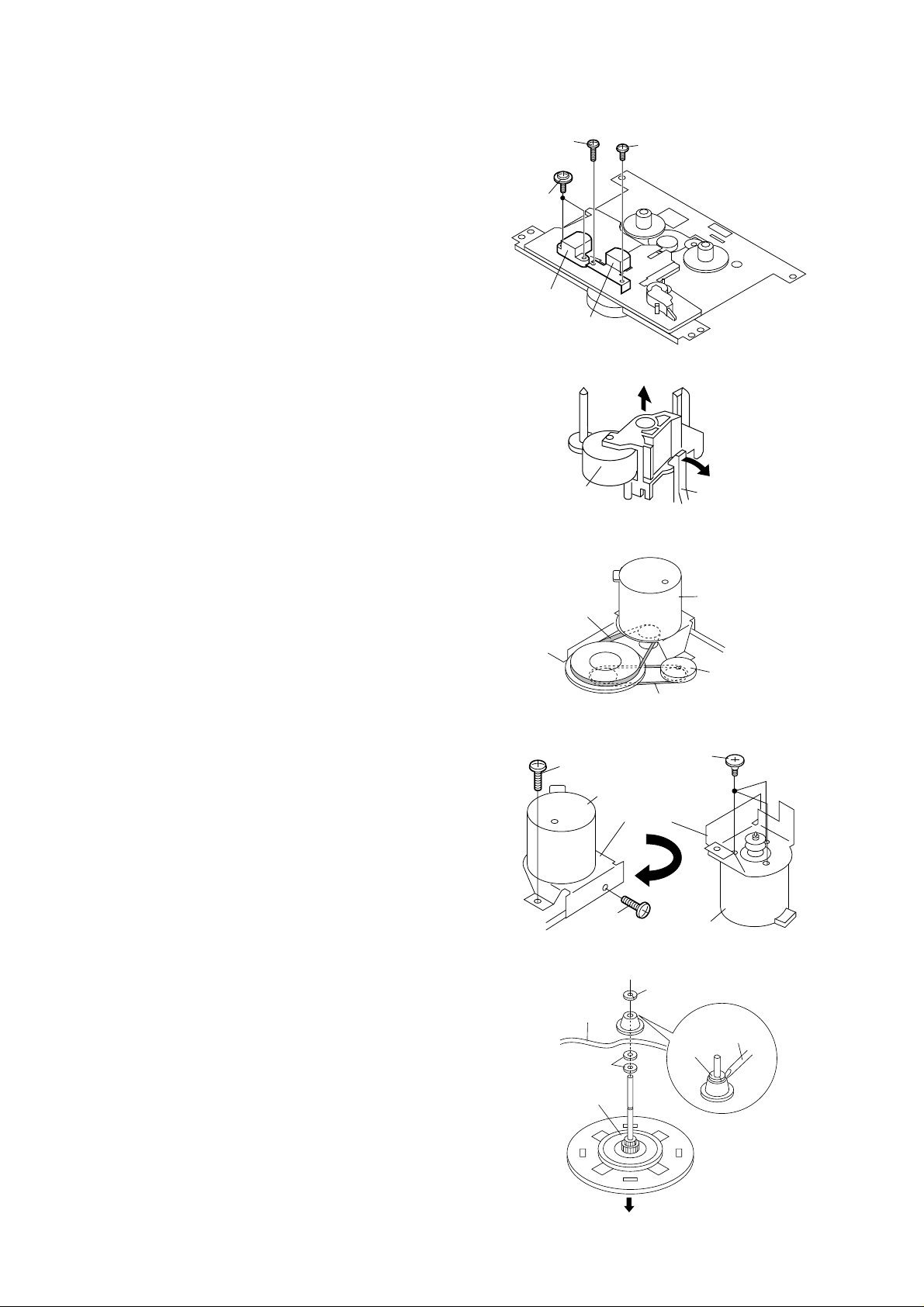
How to remove the record / playback and erase
heads (See Fig. 10-1.)
1. Remove the screws (A1) x 2 pcs., to remove the erase
head.
2. Remove the screws (A2) x 2 pcs., to remove the record/
playback head.
Note:
After replacing the heads and performing the azimuth
adjustment, be sure to apply screwlock.
How to remove the pinch roller (See Fig. 10-2.)
1. Carefully bend the pinch roller pawl in the direction of the
arrow <A>, and remove the pinch roller (B1) x 1 pc.,
upwards.
How to remove the belts (See Fig. 10-3.)
1. Remove the main belt (C1) x 1 pc., from the motor pulley.
2. Remove the FF/REW belt (C2) x 1 pc., from the REW/FF
roller.
3. Put on the belts in the reverse order of removal.
Note:
When putting on the belt, ascertain that the belt is not twisted,
and clean it.
(A2)x1
ø2x7mm
(A1)x2
ø2x8mm
Erase Head
Record/
Playback Head
Pinch Roller
(B1)x1
Main Belt
(C1)x1
(A2)x1
ø2x3mm
Figure 10-1
Figure 10-2
FF/REW Belt
(C2)x1
Figure 10-3
<A>
Pinch Roller
Pawl
Motor
REW/FF
Clutch
How to remove the motor
(See Figs. 10-4.)
1. Remove the main belt.
2. Remove the screws (D1) x 2 pcs., to remove the motor
bracket.
3. Remove the screws (D2) x 3 pcs., to remove the motor.
Note:
When mounting the motor, pay attention to the motor mounting
angle.
How to remove the flywheel (See Fig. 10-5.)
1. Remove the belt.
2. Remove the stop washer (E1) x 1 pc., with a small precision
screwdriver to extract the flywheel from the capstan metal.
Note:
When the stop washer is deformed or damaged, replace it
with a new one.
How to reinstall the parts
Install each part in the reverse order of the removal with care.
(D1)x1
ø2x4mm
Motor
(D1)x1
ø2x4mm
Mechanism
Chassis
Washerx2
Flywheel
(D2)x3
Special
Screw
Motor
Bracket
Motor
Figure 10-4
(E1)x1
Stop Washer
Stop
Washer
Driver
– 10 –
Figure 10-5
XL-70/70C
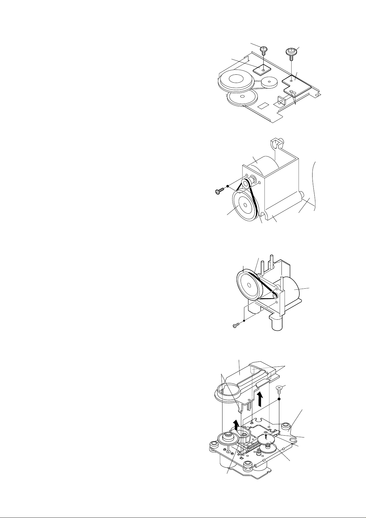
How to remove the tape mechanism PWB
(See Fig. 11-1.)
1. Remove the screws (F1) x 1 pc., to remove the tape
mechanism PWB.
2. Remove the screws (F2) x 1 pc.
3. Remove the solder joints (F3) x 2 pcs., to remove the tape
mechanism PWB.
How to remove the jog motor
(See Figs. 11-2.)
1. Remove the side panel and top cabinet.
2. Remove the jog belt (G1) x 1 pc., from the motor pulley.
3. Remove the screws (G2) x 2 pcs., to remove the jog motor.
Note:
When putting on the belt, ascertain that the belt is not twisted,
and clean it.
How to remove the CD lid motor
(See Figs. 11-3.)
1. Remove the CD PWB.
2. Remove the belt (H1) x 1 pc., from the motor pulley.
3. Remove the screws (H2) x 2 pcs., to remove the CD Lid
motor.
Note:
When putting on the belt, ascertain that the belt is not twisted,
and clean it.
Tape
Mechanism
PWB
(G2)x2
ø2x5mm
Worm
Gear
(F1)x1
ø2x3mm
Jog Motor
Worm
Gear
Figure 11-1
Jog Belt
(G1)x1
Jog Motor
Holder
Figure 11-2
(H1)x1
Belt
(F2)x1
ø2x8mm
Tape
Mechanism
PWB
(F3)x2
Solder
Joint
Display PWB
CD Lid
Motor
CD MECHANISM SECTION
Perform steps 1, 2 and 10 to 12 of the disassembly method to
remove the CD mechanism.
How to remove the pickup (See Fig. 11-4)
1. Remove the mechanism cover, paying attention to the
pawls (A1) x 4 pcs.
2. Remove the screws (A2) x 2 pcs., to remove the shaft (A3)
x 1 pc.
3. Remove the stop washer (A4) x 1 pc., to remove the gear
(A5) x 1 pc.
4. Remove the pickup.
Note:
After removing the connector for the optical pickup from the
connector, wrap the conductive aluminium foil around the
front end of connector remove to protect the optical pickup
from electrostatic damage.
(H2)x2
ø2.5x10mm
Figure 11-3
Mechanism Cover
(A1) x2
(A1) x2
(A2) x2
ø2.6 x6mm
CD Mechanism
Shaft
(A3) x1
StopWasher
(A4) x1
Gear
(A5) x1
Pickup Unit
Figure 11-4
– 11 –
XL-70/70C
MECHANISM SECTION
• Driving Force Check
Torque Meter
Play: TW-2412 Over 80 g
• Torque Check
Torque Meter
Play: TW-2111 30 to 60 g. cm
Fast forward: TW-2231 55 to 140 g.cm
Rewind: TW-2231 55 to 140 g.cm
• Tape Speed
Test Tape
MTT-111 Variable 3,000 ± Headphone
Adjusting
Point
resistor in 90 Hz terminal
motor.(M901)
TAPE MECHANISM
Specified Value
Specified Value
Specified
Value
Instrument
Connection
ADJUSTMENT
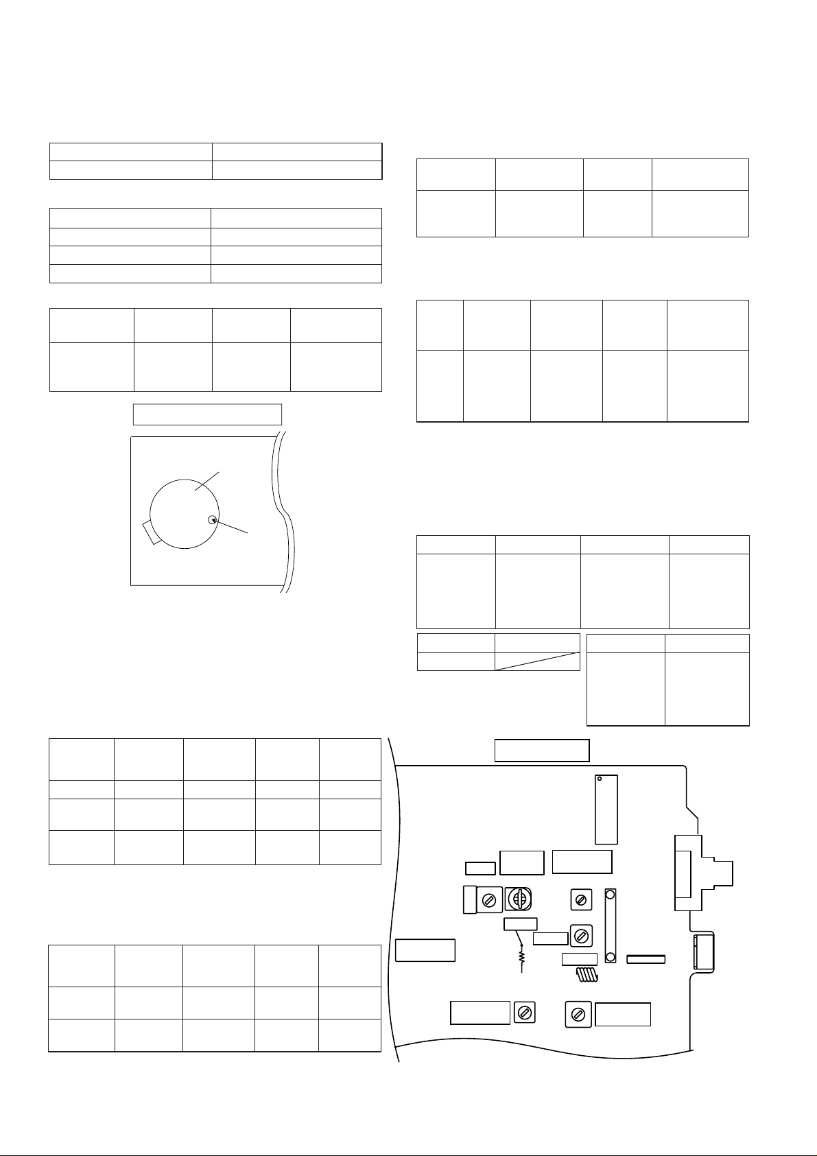
• FM Mute Level
Signal generator: 1 kHz, 40 kHz dev., FM modulated
Frequency
98.00 MHz 98.00 MHz VR351*1 Input: SO301
(30 dBµV) Output: Speaker
*1. Adjust so that an output signal appears.
• FM Detection
Signal generator: 10.7 MHz, FM sweep generator
Test
Stage
FM IF 10.7 MHz 98.0 MHz T304(Turn Input: Pin 1 of
Display
Frequency Frequency
Display
Adjusting
Parts
Terminal
Setting/
Adjusting
Parts
the core of IC301
T304 fully
counterclockwise.)
Instrument
Connection
Instrument
Connection
M901
Tape
Motor
Variable
resistor
in motor
Figure 12-1 ADJUSTMENT POINT
TUNER SECTION
fL: Low-range frequency
fH: High-range frequency
• AM IF/RF
Signal generator: 400 Hz, 30%, AM modulated
Frequency
AM IF 450 kHz 1,620 kHz T351 *1
AM Band — 522 kHz (fL): T306 *2
Coverage 1.1 ± 0.1 V
AM 990 kHz 990 kHz (fL): T302 *1
Tracking
*1. Input: Antenna, Output: Speaker Terminal
*2. Input: Input is not connected, Output: TP301
Frequency Display
Setting/
Adjusting
Parts
Instrument
Connection
• Setting the Test Mode
Keeping the FF/FWD button and MEMORY/SET button
pressed, turn on POWER. Then, the frequency is initially set
in the memory as shown in Table. Call it with the JOG DIAL
knob to use it for adjustment and check of tuner circuit.
Preset No.
1 87.5 MHz 6 530 kHz
2 108.0 MHz 7 1,720 kHz
3 98.0 MHz 8 990 kHz
4 90.0 MHz 9 600 kHz
5 106.0 MHz 10 1,400 kHz
Preset No.
11~25
FM STEREO Preset No.
BAND
Preset No.
26 106.0 MHz
27 90.0 MHz
28 98.0 MHz
29 108.0 MHz
30 87.5 MHz
AM
FM MONO
MAIN PWB
AM IF
T351
FM Mute
Level
VR351
FM Band
Coverage fL
L303
IC302
9
SO301
FM
ANTENNA
SOCKET
• FM RF
Signal generator: 1 kHz, 75 kHz dev., FM modulated
Test Stage
FM Band — 87.5 MHz (fL): L303 *1
Coverage 3.4 ± 0.1 V
FM RF 98.00 MHz 98.0 MHz L302 *2
Frequency
(10~30 dB)
Frequency
Display
Setting/
Adjusting
Parts
Instrument
Connection
*1. Input: Antenna, Output: TP301
*2. Input: Antenna, Output: Speaker Terminal
– 12 –
IC303
FM IF
L302
T304
FM RF
T302
1
AM
Tracking fL
CF352
R336
AM Band
Coverage fL
TP301
T306
Figure 12-2 ADJUSTMENT POINTS
IC301
BF301
CNP301
AM
ANTENNA
SOCKET
XL-70/70C
TEST MODE
The test mode applied to this microcomputer has three modes, namely ordinary test mode to be used for adjustment or
measurement, aging test mode to be used for aging test, and self-diagnosis test mode for self-inspection in case of final product
inspection.
1. Turning on the test mode
To turn on the specific test mode, press the POWER button, holding down the following two buttons in the ordinary stand-by
mode (power off state). In this case only the main unit button is valid. Even when the POWER of remote control button is set
to on, the test mode is not turned on.
[Ordinary test mode]
1. CD Test Mode (TEST 1)…………………… Volume/JOG Dial Selector + FF/FWD
2. Tuner Test Mode (TEST 2)………………… Volume/JOG Dial Selector + Volume Select
3. Electronic volume Test Mode (TEST 3)……REW/REV + FF/FWD
4. Timer Test Mode (TEST 4)………………… FUNCTION + Volume Select
5. LCD Test Mode (TEST 5)……………………FUNCTION + FF/FWD
[Self-diagnosis Test Mode]
1. Button input diagnosis test mode (TEST6).…
REW/REV + Volume Select
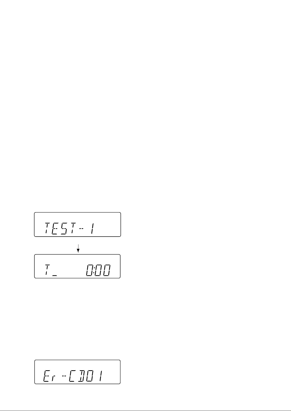
2. CD Test Mode (TEST 1)
In the CD test mode the operation of each step is enabled even when the LID-SW is off. However, if focus cannot be set in step
3 or any error processing is started, it is impossible to proceed to the next step. When the error processing is started, operations
other than termination of test mode by pressing the POWER button or return to the step 1 by pressing the STOP button are inhibited.
1. Step 1 Mode
When the CD test mode is turned on, the following indication lights, the processing (until turning-off of CD STB terminal of CD
initialization operation flow) is executed, and the next button input is waited.
After lighting for one second
If the following operation buttons are pressed in this state, the operation is performed as follows.
"POWER".................The test mode is turned off, the power is turned off, and the ordinary standby mode is set.
"FF/FWD".................After the pickup returns once to the innermost periphery, it slides toward the outer periphery while this
button is held down.
"REW/REV"..............After the pickup returns once to the innermost periphery, it slides toward the inner periphery while this
button is pressed. However, if PU-IN is on, input is invalid.
"PLAY" .....................Shift to step 2
"STOP".....................Invalid
"REC PAUSE"..........Shift to step 5
* In case of initialization the pickup is moved toward the inner periphery. Any buttons other than "POWER" button are not
accepted until the shift of pickup to the inner periphery is completed at this time. If PU-IN SW ON cannot be detected within
10 seconds, the slide motor is stopped, and the following error indication appears. Press the POWER button to end the test
mode, or press the STOP button to return to step 1. Any other operations are inhibited.
– 13 –

XL-70/70C
2. Step 2 Mode
When the "PLAY" button is pressed in this mode, the laser lighting command LDON (8400) is sent, and the laser is turned on.
Other operations are not performed.
If the following buttons are pressed in this state, the operation is performed as follows.
"POWER" ................ The test mode is turned off, the power is turned off, and the ordinary standby mode is set.
"FF/FWD" ................The pickup slides toward the outer periphery while this button is held down.
"REW/REV" .............The pickup slides toward the inner periphery while this button is held down. However, if PU-IN is on, input
is invalid.
"PLAY".....................Shift to step 3
"STOP" ....................Return to step 1
"REC PAUSE" .........Shift to step 5
3. Step 3 Mode
The laser is kept lighting. The processing (until turning-on of CLV servo of CD initialization operation flow) is executed, and
the next button input is waited. (The focus servo is turned on, and focus search is performed.)
The focus search is repeated until the focus is set.
When the following operation buttons are pressed in this state, the operation is executed as follows.
"POWER" ................The test mode is turned off, the power is turned off, and the ordinary standby mode is set.
"FF/FWD" ................The pickup slides toward the outer periphery while this button is held down.
"REW/REV" .............The pickup slides toward the inner periphery while this button is held down. However, if PU-IN is on, input
is invalid.
"PLAY".....................If the focus has been set, shift to step 4 is executed. If the focus has not been set, acceptance is inhibited.
"STOP" ....................Return to step 1
"REC PAUSE" .........Shift to step 5
*If the focus is disturbed after it has been set, the process returns to step 1.
4. Step 4 Mode
The CLV servo ON command (8600) sending operation is performed, and the next button input is waited. (The disc is rotated
to perform CLV locking.)
The time display indicates always "0:00".
When the following buttons are pressed in this state, the operation is executed as follows.
"POWER" ................The test mode is turned off, the power is turned off, and the ordinary standby mode is set.
"FF/FWD" ................The pickup slides toward the outer periphery while this button is held down.
"REW/REV" .............The pickup slides toward the inner periphery while this button is held down. However, if PU-IN is on, input
is invalid.
"PLAY".....................Shift to step 5
"STOP" ....................Return to step 1
"REC PAUSE" .........Shift to step 5
*If the focus is disturbed, the process returns to step 1.
– 14 –
XL-70/70C
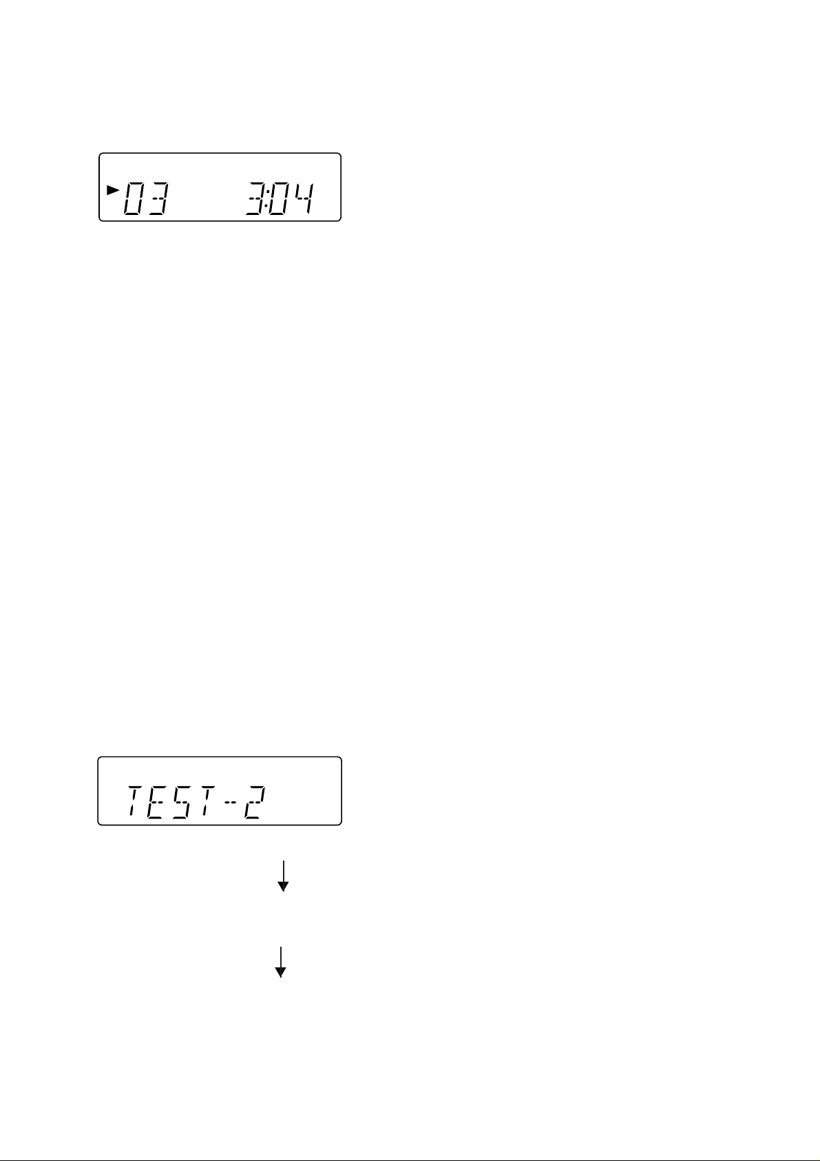
5. Step 5 Mode
The CD initialization operation flow is executed to the end, the mute is set to off, and playback is started. Even when the
playback reaches the outermost periphery of disc, the operation does not stop. The LCD display indicates the playback past
time as in case of ordinary CD playback.
When the following operation buttons are pressed in this sate, the operation is executed as follows.
"POWER".................The test mode is turned off, the power is turned off, and the ordinary standby mode is set.
"FF/FWD"................. The pickup slides toward the outer periphery while this button is held down.
"REW/REV"..............The pickup slides toward the inner periphery while this button is held down. However, if PU-IN is on, input
is invalid.
"PLAY" ..................... Invalid
"STOP".....................Return to step 1
*If the focus is disturbed, the process returns to step 1.
Other cautions
• TOC IL is not executed in the test mode.
• As for button operations other than those shown above, only the sound volume operation (with JOG) is accepted.
3. Tuner Test Mode (TEST 2)
1. Outline of tuner (radio) test mode
The tuner test mode is intended to store the adjustment and measurement frequencies in the preset memory CH without
frequency setting by adjusting personnel when the tuner section is adjusted in the production line.
2. Details of tuner test mode
When the power is turned on by using the "POWER" button while the "Volume/JOG Dial Selector" and "Volume Select"
buttons are held down in POWER OFF state, the frequency for adjustment and measurement of destination specified by the
AREA terminal is preset and stored in the preset memory CH. However, Ordinary 1 and Ordinary 2 are set to the designation
(destination selected by SPAN switching operation) set when the test mode is set. (As for frequencies to be preset and stored
for each destination, refer to item 3.)
The tuner test mode is started from preset No.1.
The operations of test mode are identical with the ordinary operations of TUNER function. However, FUNCTION switching
is invalid.
Since it is necessary to discard the content of preset memory when the tuner test mode is ended, "0000" or "1111" bits are
written in the memory to be checked in case of memory check (in case of initial setting) so that memory abnormality is detected
in case of initial setting so as to ensure memory initialization.
When the tuner test mode is turned on, the following indication lights for one second.
• The TUNER TEST2 mode is set as a result of Volume Select + POWER. -> IF AC is set to OFF in the TEST2 mode, the initial
state is restored.
When POWER is set to OFF, the memory of TEST2 mode is protected.
When the power is turned on again, the ordinary operation is enabled while the data is stored in the
memory (besides TUNER).
If AC OFF state is maintained in this state for about 1/2 day, start is executed in the initial state.
• To clear the whole memory, insert the AC cord, holding down MEMORY + PLAY.
– 15 –
XL-70/70C
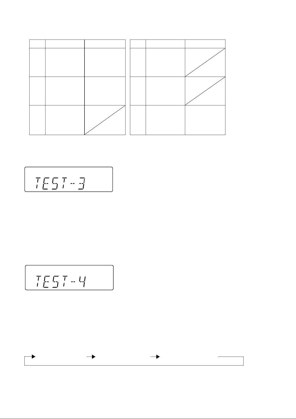
3. Preset frequencies for various destinations (random preset memory)
U.S.A. ,BrazilCH
1 FM 87.5 MHz
2 FM108.0 MHz
3 FM STEREO FM 98.0 MHz
4 FM 90.0 MHz
5 FM106.0 MHz
6 AM 530 kHz
7 AM1720 kHz
8 AM AM 990 kHz
9 AM 600 kHz
10 AM1400 kHz
11
12
13 LW
14
15
• The hatched sections of the table are not stored in memory.
4. Electronic volume Test Mode (TEST 3)
When the test mode is set, the following indication lights for one second.
16
17
18
19
20
21
22
23
24
25
26 FM106.0 MHz
27 FM 90.0 MHz
28 FM MONO FM 98.0 MHz
29 FM108.0 MHz
30 FM 87.5 MHz
BAND
U.S.A. ,BrazilCHBAND
When this mode is set, BASS/TREBLE is set to 0 (0 dB) and SURROUND mode is set to off, and start-up function is set to CD
when volume is -14 dB (STEP 17). The button operations in the test mode are the same as those of ordinary operation excepting
sound volume UP/DOWN.
(1) The indication is the same as that of ordinary operation excepting test mode setting.
(2) The sound volume control with the sound volume UP/DOWN button is only the following 3 steps unlike the ordinary state.
Volume- ∞ (STEP 0) <-> Volume-14 dB (STEP 23) <-> Volume-0 (STEP 30)
(3) BASS/TREBLE and SURROUND are switched when button operation is performed.
5. Timer test Mode (TEST 4)
When the test mode is set, the following indication lights for one second.
The current time and timer time are set in the following procedure to perform the timer playback.
1.Set the current time to 1:00, set the timer to ON time 1:02, set the function to Tape, and set volume STEP 8. One minute is counted
as one second, and the timer playback operation is performed. The fade-in (when playback is started) is executed at a rate of
one step for 0.5 sec. After completion of fade-in the fade-out is executed at a rate of one step for 0.5 sec (WAIT 1 sec inserted).
After completion of fade-out the power is turned off (after WAIT 1 sec), and the mode is changed to the standby mode.
The indication during operation is the same as that of ordinary timer operation.
6. LCD Test Mode (TEST 5)
When the LCD test mode is set, all the LCD segments are lighted. After that the indication is changed as follows according to
the "PLAY" button input.
Lighting of all segments Lighting of odd segments Lighting of even segments
– 16 –
XL-70/70C
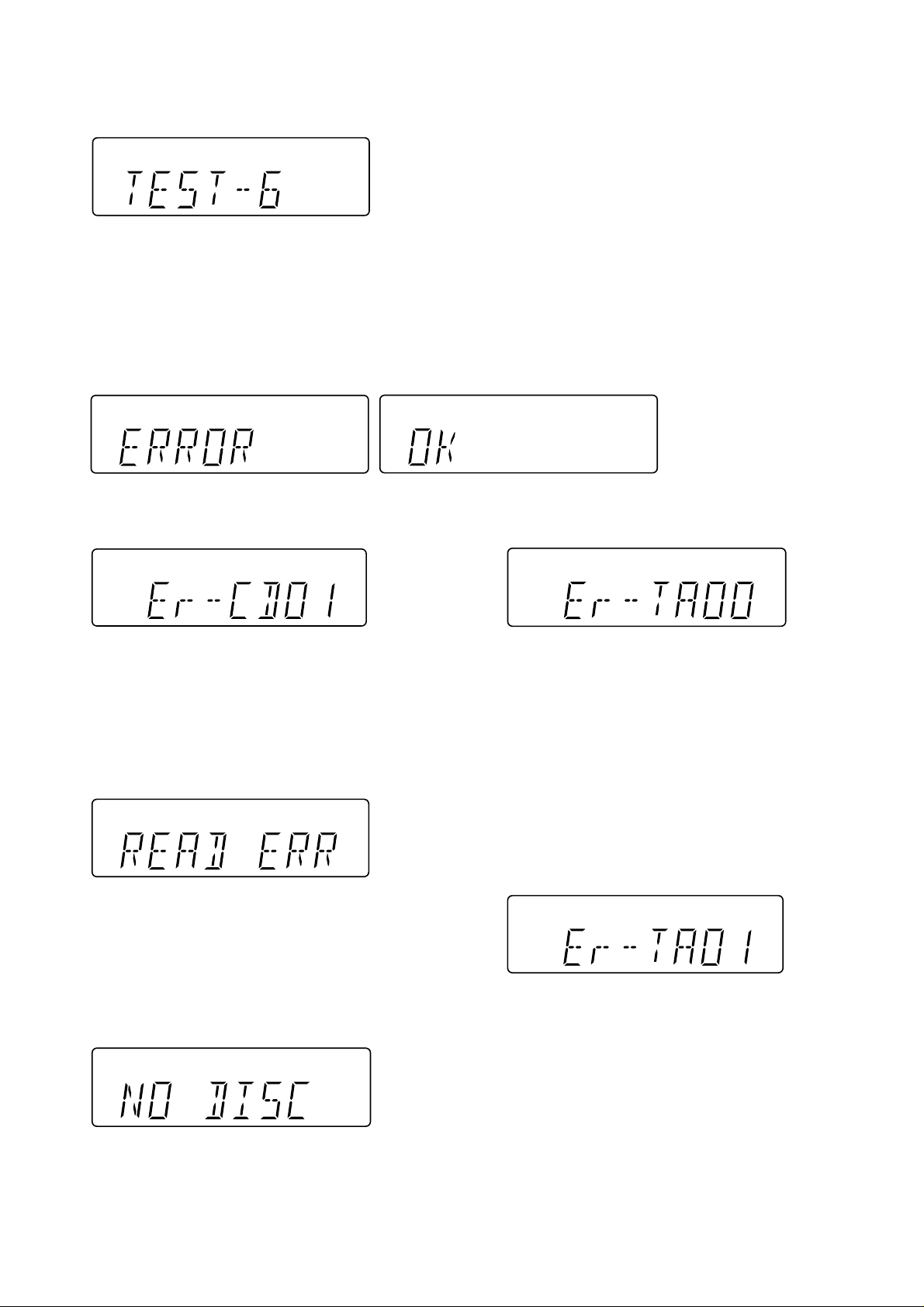
7. Key input diagnosis Test Mode (TEST 6)
When the test mode is set, the following indication appears.
This test mode is intended to check whether all the main unit buttons can be detected. Accordingly, in this test mode checking
as to whether the "POWER" button was pressed after all the buttons shown below were pressed is performed. If the result is
OK, OK is indicated. Even any one of keys was not pressed, an error is indicated. In case of OK termination or error termination
exit from this mode occurs when the "POWER" button is pressed next time, and the standby mode is set.
1. In case of "Review" + "Volume/Jog Dial Select Button"
The following 13 buttons are detected as all buttons.
The OK/NG indication of test result is as follows.
ERROR LIST
PU-IN SW detection error
Tape mechanism error 1
Error content............ The detection SW cannot detect ON
after a fixed period of time even if the
microcomputer controls the CD pickup
to return to the innermost position.
Probable cause........Defective or poorly connected PU-IN
SW or slide motor.
Action .......................Solve the problem and turn on the power
again.
CD read error
Error content ........... Disc data cannot be read properly or
even if it can be read, the disc is not a
playable one.
Probable cause....... The disc is loaded upside down, not CD-
DA, scratches, stains, etc.
Action ...................... Open the CD lid, then reload the disc
correctly. Remove the scratches or stains
on the disc.
NO DISC
Error content ........... Focusing is impossible.
Probable cause....... The disc is loaded upside down, not CD-
DA, scratches, stains, etc.
Action ...................... Open the CD lid, then reload the disc
correctly. Remove the scratches or stains
on the disc.
Error content........... The detection SW "CAM-SW" cannot
detect ON (mechanism in operation) even
if the motor and solenoid are controlled
to play back, fast forward, rewind, or
record the tape.
Probable cause....... Mechanism is in operation when this
message appears: Defective or poorly
connected CAM-SW. Mechanism stops:
Defective or poorly connected motor or
solenoid.
Action ...................... Solve the problem and turn on the power
again.
Tape mechanism error 2
Error content ........... Initialization cannot be completed when
the microcomputer controls the motor
and solenoid to initialize the tape
mechanism (to set the mechanism to the
stop mode). The detection SW "CAMSW" cannot detect OFF While the
mechanism is in operation.
Probable cause....... Mechanism is in operation when this
message appears: Defective or poorly
connected CAM-SW. Mechanism stops:
Defective or poorly connected motor or
solenoid.
Action ...................... Solve the problem and turn on the power
again.
– 17 –
XL-70/70C
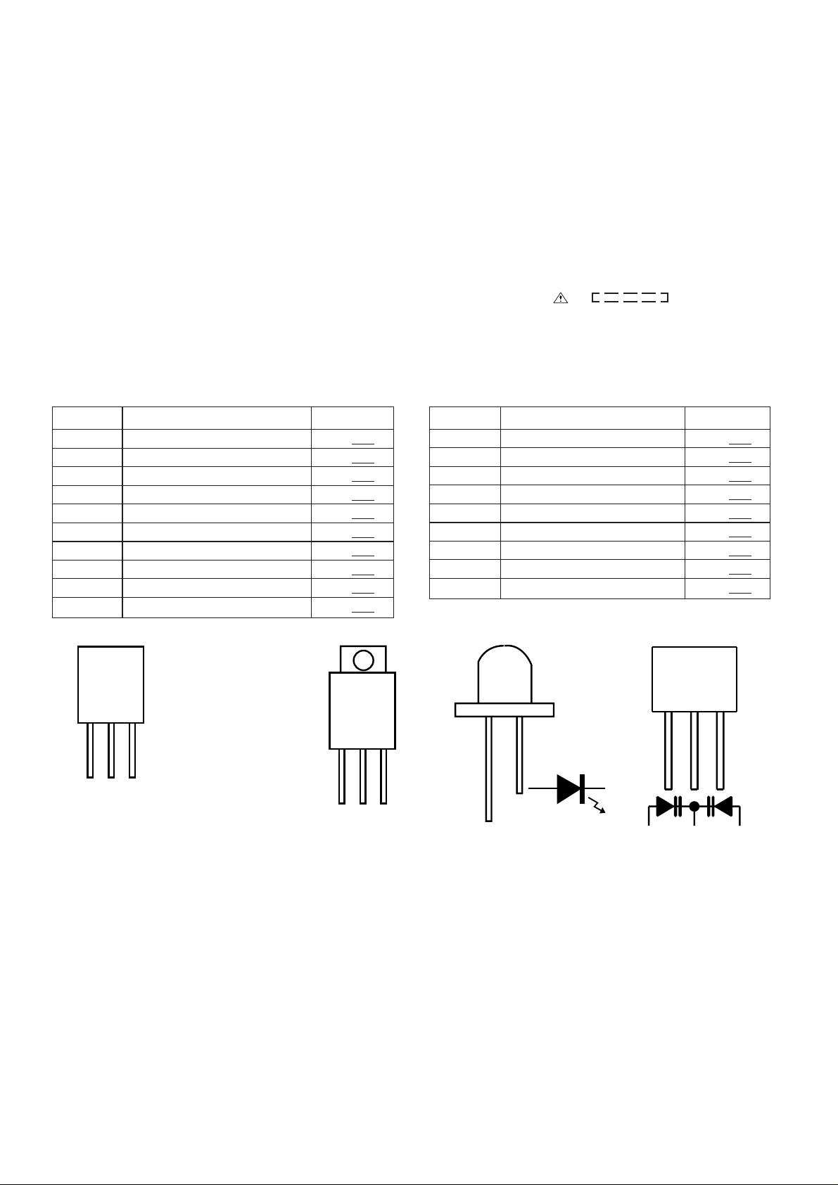
NOTES ON SCHEMA TIC DIAGRAM
• Resistor:
To differentiate the units of resistors, such symbol as K and
M are used: the symbol K means 1000 ohm and the symbol
M means 1000 kohm and the resistor without any symbol is
ohm-type resistor. Besides, the one with “Fusible” is a fuse
type.
• Capacitor:
To indicate the unit of capacitor, a symbol P is used: this
symbol P means micro-micro-farad and the unit of the
capacitor without such a symbol is microfarad. As to
electrolytic capacitor, the expression “capacitance/withstand
voltage” is used.
(CH), (TH), (RH), (UJ): Temperature compensation
(ML): Mylar type
(P.P.): Polypropylene type
• Schematic diagram and Wiring Side of P.W.Board for this
model are subject to change for improvement without prior
notice.
REF. NO DESCRIPTION POSITION POSITIONREF. NO DESCRIPTION
NSW801 PICKUP IN ON—OFF
SW700 JOG ON—OFF
SW709 ON/STAND-BY ON—OFF
SW710 CLOCK/TIMER/SLEEP ON—OFF
SW711 TUNING UP ON—OFF
SW712 PLAY/CD PAUSE ON—OFF
SW713 VOLUME SELECT ON—OFF
SW721 MEMORY/SET ON—OFF
SW722 BASS/TREBLE ON—OFF
SW723 BAND ON—OFF
• The indicated voltage in each section is the one measured
by Digital Multimeter between such a section and the chassis with no signal given.
1. In the tuner section,
( ) indicates AM
< > indicates FM stereo
2. In the main section, a tape is being played back.
3. In the deck section, a tape is being played back.
( ) indicates the record state.
4. In the power section, a tape is being played back.
5. In the CD section, the CD is stopped.
• Parts marked with “ ” ( ) are important for
maintaining the safety of the set. Be sure to replace these
parts with specified ones for maintaining the safety and
performance of the set.
SW724 REC. PAUSE ON—OFF
SW725 STOP/CLEAR ON—OFF
SW726 TUNING DOWN ON—OFF
SW727 FUNCTION ON—OFF
SW728 VOLUME JOG ON—OFF
SW730 CD LID OPEN/CLOSE ON—OFF
SW802 CD LID ON—OFF
SW901 FOOL PROOF ON—OFF
SW902 CAM ON—OFF
FRONT
VIEW
ECB
(S)(G)(D)
(1) (2) (3)
2SB562 C
2SC2001 K
2SC535 C
2SD468 C
KRA102 M
KRC102 M
KRC104 M
KRC107 M
KTA1266 GR
KTC3199 GR
FRONT
VIEW
BCE
2SD2012 Y
Figure 18 TYPES OF TRANSISTOR AND LED
MPG3372X
HY2043
FRONT
VIEW
1 2 3
SVC348S
KDV147B
– 18 –
 Loading...