

Page 1

3-859-268-11(1)
XES-M50
Operating Instructions
1997 by Sony Corporation
Page 2

Page 3

Stereo Power
Amplifier
Operating Instructions
Before operating the unit, please read this manual thoroughly and
retain it for future reference.
Owner’s Record
The model and serial numbers are located on the bottom of the
unit.
Record the serial number in the space provided below.
Refer to these numbers whenever you call upon your Sony dealer
regarding this product.
Model No. XES-M50 Serial No.
Page 4

Introduction
Contents
Introduction
Contents .............................................. 2
Features............................................... 3
Installation
Installation .......................................... 4
Before Installation ....................... 4
Parts List ....................................... 4
Installation Instructions ............. 5
Connections
Before Connecting ............................. 6
System Connections (XES Series).... 7
Power Supply Lead Connections.... 8
XES Series Speaker Connections ..... 9
Speaker Connections
When Used as a Monophonic
Amplifier (Bridging
Connections) .............................. 10
Dual Mode Connections .......... 11
Using a Monophonic Amplifier
for Subwoofer Use (Bridging
Connection)................................ 13
Adjustment
NFB Switch ....................................... 14
Phase Switch .................................... 14
Input Level Adjustments................ 15
Other
Precautions ....................................... 16
Precautions on Use ................... 16
Fuse Replacement ..................... 16
Troubleshooting Guide .................. 17
Specifications ................................... 18
Power Supply Wire ......................... 19
2 Introduction
Page 5

Features
Left and right channel independent
monophonic configuration
Two amplifiers are laid out in a single
unit and everything is kept separate,
even the power supply terminals, so a
clear sound quality is realized with
almost no interference between signals
of the left and right channels.
Equipped with a Non-NFB circuit for
clear sound reproduction
Conventional NFB (Negative Feed Back)
circuits are effective at reducing the
distortion produced by the amplifier but
are susceptible to the affects of sound
muddiness from the reverse
electromotive force produced by the
speakers. This system is equipped with
a Non-NFB circuit for handling this
problem so a clear, unmuddied sound is
reproduced.
In addition, output transistor source
resistance is removed and the speakers
are driven directly. Because there is no
source resistance, switching distortion is
suppressed and pure transmission is
possible.
Pre-Regulated Power Supply with no
fluctuations in constant voltage even
during large outputs of power and
when the engine is running
Once constant voltage has been attained,
a Pre-Regulated Power Supply that steps
up with a DC/DC converter is
employed for the power source of the
voltage amplification stage. A choke
coil-less method is employed in the
power input of the current amplification
stage and the current drive capacity is
ensured. As a result of these, a powerful
power source is realized that is capable
of driving both channels at 200 W each
at 1 ohm.
FET Input Circuit
Differential amplifier circuit with
positive/negative symmetry due to the
use of dual FET. Dual FET with tips of
all characteristics contained in one
package are used, and allowances have
been made for thermal coupling. In
addition, using the high input
impedance of the FET gates, a DC input
circuit is attained that does not use DC
coupling capacitors.
High Quality Parts Used
Parts that combine reliability with high
sound quality are used in the system
including newly developed aluminum
power capacitors, power transformers in
which allowances have been made for
vibration, a planed terminal board, RCA
pin jacks, a gold-plated oxygen free
copper substrate, and carbon resistant
materials, etc.
Introduction
3
Page 6
InstallationInstallation
Installation
Before Installation
• Mount the unit either inside the trunk or under a seat.
• To mount the unit you will need a mounting board that is sufficiently thick (at least
15 mm (
• When mounting the unit horizontally, mount it on the heat sink surface. Also,
avoid installing the unit under the carpet as the heat dissipation will be
considerably impaired.
• Because a DC-DC converter is used in this unit, if it is mounted near the radio or
antenna, reception of radio and television broadcasts will be hindered. Set the unit
up in a place as far away as possible from the radio and antenna.
• Do not install it in a place where it is exposed to high temperatures, such as in
direct sunlight, or where it is directly exposed to hot air from the heater.
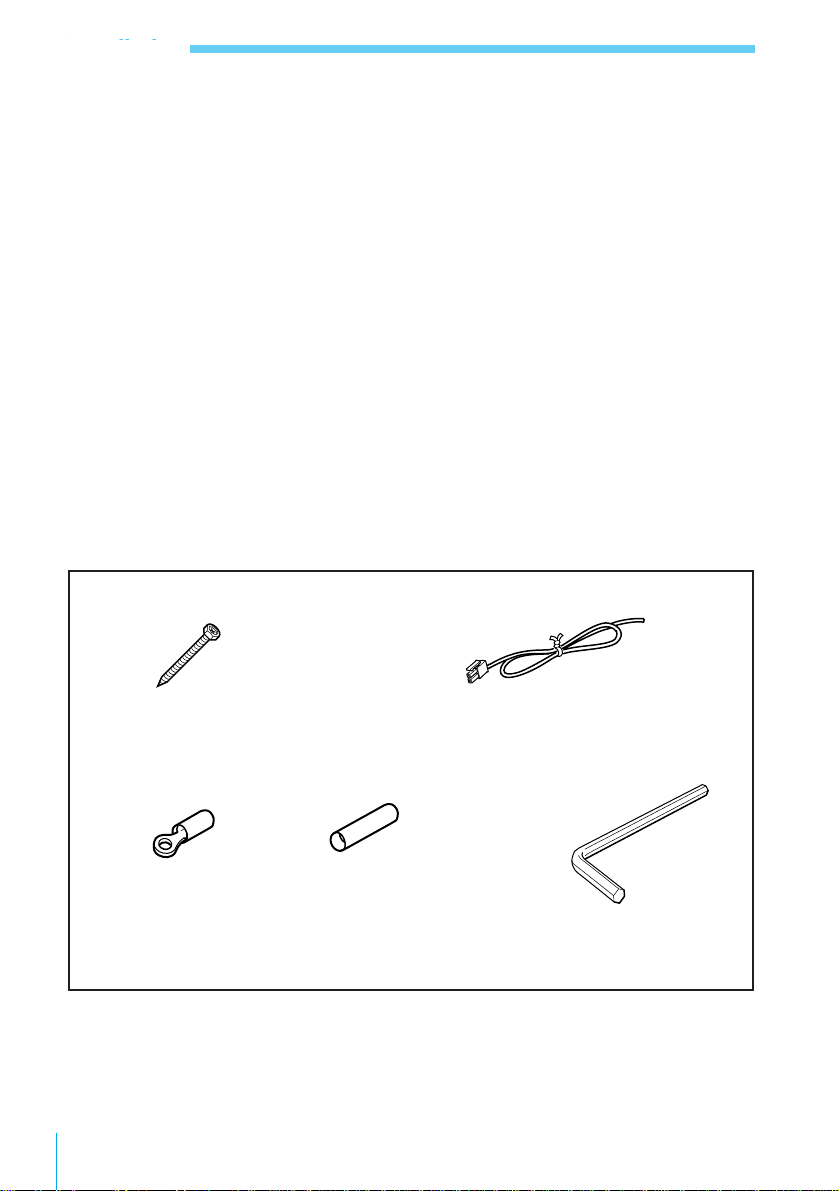
Parts List
The circled numbers indicate the number of the part to use that is referred to in the
explanation of how to install the unit.
19
/32 in.)) and strong.
4 Installation
1
× 4
Screws (φ5 × 40 mm)
(φ 7/32 × 1 5/8 in.)
3
red × 4,
black × 4
Crimp type terminals
2
Remote cords (blue/white)
4
× 2
Blue junction crimp type
terminals (for junctions in
the wiring)
× 2
5
× 1
Hexagonal wrench
Page 7
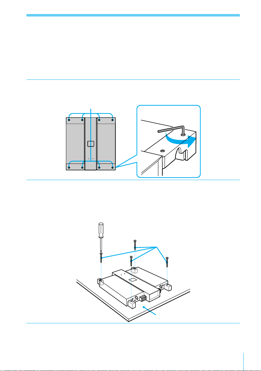
Installation Instructions
Prepare a mounting board that is sufficiently thick (at least 15 mm (19/32 in.)) and
strong.
1 Remove the cover.
Loosen and remove the 8 screws using the hexagonal wrench 5.
Screw positions
Hexagonal wrench 5
2 Mount the unit on the mounting board.
Place the template (printed on the carton box) on the mounting board, determine
where the unit will be mounted and mark the hole positions. Drill holes of at
least 3 mm (1/8 in.) in diameter at the places you have marked, and using the
screws 1, secure the unit on the mounting board.
Screws 1
Mounting board
3 Attach the cover.
Reattach the cover with the hexagonal wrench 5 using the screws removed in
Step 1.
Installation
5
Page 8
ConnectionsConnections
Before Connecting
• Before making any connections,
disconnect from the negative terminal
of the car battery to avoid short
circuits.
• Always connect the power supply
lead last.
• Install the input and output cords
away from the power supply lead as
running them close together can
generate some interference noise.
• This unit is a high powered amplifier.
Therefore, it may not perform to its
full potential if used with the speaker
cords already established in the car.
• Connecting the } terminal of the
speaker system to the car chassis or
connecting the } terminal of the right
speaker with that of the left speaker
may result in damage.
• Be sure to use speakers with an
adequate power rating. Because this
amplifier puts out high power, if you
use small capacity speakers, not only
will the amplifier not perform at its
full potential, but the speakers may
become damaged as well.
• Use speakers with an impedance of 18 ohms. (2-8 ohms with a bridging
connection)
• Do not connect the active speaker
(speaker built into the amplifier) to a
speaker terminal on the amplifier as
this may damage the speaker.
Caution
If your car is equipped with a computer
for navigation or some other purpose,
do not remove the ground wire from the
negative terminal of the car battery. If
you disconnect the wire, the computer
memory will be completely erased.
With these types of vehicles, without
disconnecting the power supply lead
from the negative terminal of the
battery, make all the other connections
first leaving the connection to the power
supply for last.
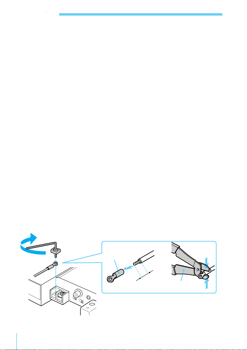
Make the power supply lead and speaker connection as illustrated below.
Crimp type
terminal 3
b
5mm
in.)
32
Crimping wrench
/
7
(
In order not to damage the screws, the tightening torque should be no more than
1 Nm.
6 Connections
Page 9

System Connections (XES Series)
Digital Reference Sound System XES-Z50
SUBWOOFER MID
Power Amplifier
XES-M50
30 cm Subwoofer
XES-L50
Power
Amplifier
XES-M50
16 cm Full Range
Speaker XES-F50
HIGH
Power
Amplifier
XES-M50
Ribbon Tweeter
XES-H50
Connections
7
Page 10

Connections
Power Supply Lead Connections
For safety reasons it is recommended that you use the crimp type terminals provided
for connecting to the power supply lead.
REMOTE +12V+12V GNDGND
Minimum of 12 AWG
(not supplied)
to a metal point
of the car
Minimum of 12 AWG
(not supplied)
REM OUT
XES-Z50
If you have the factory original or some other
car audio that does not have a remote output,
connect the remote input terminal (REMOTE)
of this unit to the accessory power supply.
Caution
• Connect the power supply lead last
after all the other connections have
been made.
• Be sure to connect the ground lead of
the unit securely to a metal point on
the car. A loose connection may result
in damage.
• Connect the remote output lead of the
car audio to the remote input terminal
(REMOTE) of this unit. If there is no
amplifier remote output in the car
audio, connect the remote input
terminal to the accessory power
supply of the car.
8 Connections
Distributor
(not supplied)
To improve sound quality,
the power supply of the
XES-Z50 should not pass
through the distributor
but should be wired
separately.
• When using a direct power supply
Example: Wiring from the distributor
to the battery
4-ohm speaker × 2 (7.5 A × 2)
+ 1-ohm speaker × 2 (26 A × 2)
+ 1-ohm speaker × 2 (26 A × 2)
= 119 A
AWG 4 is necessary provided the length
is 5 m (16 ft. 5 in.).
50 A-150 A fuses for 1 to 3 speakers
Power supply capacity varies
depending on the impedance of the
speaker(s).
]}
12 V battery
from the car battery, refer to the table
on page 21 to select the appropriate
cord.
Page 11

XES Series Speaker Connections
*Optional
XES-Z50*
RCA pin cord (not supplied)
MID LINE OUT SUBWOOFER LINE OUT
HIGH LINE OUT
INPUT LEFT
NORM
INV OFF
ON
NFB
]}
**
Right speaker
XES-F50*
Left speaker
Speaker
cords (not
supplied)
Left speaker
PHASE
]}
XES-F50*
Caution
• The wiring of the cables of the
speakers that are used should be kept
short because the XES-F50 and XESL50 speakers of the XES Series are
SPEAKER
OUT
]}
XES-H50*
INPUT RIGHT
Accessories
3
INV
OFF
PHASE
NORM
ON
NFB
]}
Left speaker
Right speaker
XES-H50*
]}
XES-L50*
** Accessories supplied
with the speakers
]}
Right speaker
XES-L50*
1 ohm devices. If the cables are too
long, the system will not be able to
perform at its full potential.
**
Connections
9
Page 12

Connections
Speaker Connections
When Used as a Monophonic Amplifier (Bridging Connections)
Car audio
RCA pin cord
(not supplied)
Left channel
INPUT RIGHT
INPUT LEFT
NORM
PHASE
INV OFF
SPEAKER
ON
NFB
OUT
]
Left speaker
(2 ohms or more)
]
ON
OFF NORM
NFB
}
INV
PHASE
Note
Make sure that the same signals are
input to the INPUT RIGHT/LEFT
connectors on the respective amplifier.
NORM
Speakers cords
(not supplied)
LINE OUT
INV OFF
PHASE
INPUT RIGHT
INPUT LEFT
SPEAKER
ON
NFB
OUT
]
Right speaker
(2 ohms or more)
Right channel
]
ON
NFB
}
OFF
INV
PHASE
NORM
10 Connections
Page 13

Dual Mode Connections
Car audio
LINE OUT
RCA pin cord (not supplied)
INPUT LEFT
NORM
INV OFF
PHASE
C (capacitor)* C (capacitor)*
}
]
Left full range
speaker
(1 ohm or more)
NFB
INPUT RIGHT
ON
SPEAKER
OUT
L (coil)*
Speakers cords
(not supplied)
]
}
Subwoofer
(2 ohms or more)
* See the table on the following page for coil and
capacitor crossover frequency relationship.
INV
OFF
PHASE
NORM
ON
NFB
}
Right full range
speaker
(1 ohm or more)
]
Connections
11
Page 14

Connections
Relationship between crossover frequencies, the inductance of the coil, and the
capacitance of the capacitors when a dual connection has been established (6 dB/oct.
4 ohms).
Crossover Frequency (Hz) L(Coil) (not supplied) (mH) C1/C2 (Capacitors) (not supplied) (µF)
50 12.7 800
80 8.2 500
100 6.2 400
130 4.7 300
150 4.2 270
200 3.3 200
260 2.4 150
400 1.6 100
600 1.0 68
800 0.8 50
1000 0.6 39
Caution
• When combined with a multiway
loudspeaker system using a passive
crossover network, make sure that the
impedance of the entire system is at or
higher than the matching impedance
level.
• When a 12dB/oct passive crossover
network is established in which the
capacitors and coils are arranged in a
series, always connect the speakers. If
disconnected from either the ] or }
terminal of a speaker, the impedance
in the vicinity of the resonance
frequency decreases and a condition
approaching short circuiting occurs.
This may result in abnormal amounts
of heat being generated or in damage
to the system.
12 Connections
Page 15

Using a Monophonic Amplifier for Subwoofer Use (Bridging Connection)
Car audio
LINE OUT
RCA pin cord (not supplied)
INPUT LEFT
NORM
INV OFF
NFB
ON
PHASE
]}
30 cm Subwoofer XES-L50
* See the table in “Dual Mode
Connections” (preceding page) for
information on crossover frequencies
and the inductance of L (a coil which
is not supplied). Connections can also
be made using a passive low-pass
filter (not supplied).
SPEAKER
OUT ]
Speaker cords
(not supplied)
L*
Caution
Connected in this way, the sound of the
subwoofer will conform to the signals
input to both the left and right terminals.
INPUT RIGHT
INV
OFF
PHASE
NORM
ON
NFB
Connections
13
Page 16

Adjustment
Adjustment
NFB Switch
NFB (Negative Feed Back) circuits are
effective at reducing the static
characteristic distortion produced by the
amplifier but are susceptible to the
affects of sound muddiness from the
reverse electromotive force produced by
the speakers.
With a Non-NFB circuit, a clear,
unmuddied sound is reproduced.
NFB switch
Phase Switch
Used to switch speaker phase.
Operates as a positive gain amplifier
when set to NORM (normal), and as a
negative gain amplifier when set to INV
(invert).
PHASE switch
14 Adjustment
Page 17

Input Level Adjustments
When connecting a car audio system of
another manufacturer the input level
must be adjusted with the LEVEL
controls. Turn it to MAX when the
input level seems low and to MIN when
the input level seems high.
LEVEL controls
Adjustment
15
Page 18

Other
Precautions
Precautions on Use
• If your car is parked in direct sunlight
with the windows closed the
temperature inside it rises
considerably. At such times, allow the
humidity level inside the car to drop
before using the system.
• The protection circuit inside the
amplifier will operate under the
following circumstances in order to
protect the output transistor and the
speakers:
– when the level of temperature
inside the amplifier has become
excessive
– when an abnormality has occurred
and a DC voltage has been
generated
– when an output terminal has been
short circuited
At this time the color of the POWER/
PROTECT indicator will change from
green to red and sound will no longer
be audible from the speakers. If this
happens, turn off the connected
equipment immediately and
investigate the cause of the
malfunction. When you think that
overheating is the cause, wait until the
unit cools down before using.
• Do not use the unit on a weak battery
as it depends on the condition of the
battery for optimal performance.
• For safety reasons, keep the volume at
a level that allows you to hear sounds
outside the vehicle when driving.
• Do not obstruct the ventilation holes
provided for the fan.
Fan
Fuse Replacement
When a short circuit occurs or the unit is
damaged, a fuse blows preventing
excessive current from flowing into the
unit. If a fuse blows, check the power
source and ground lead connections and
replace the fuse. If a fuse blows again
soon after it has been replaced, consult
your nearest Sony dealer.
16 Other
POWER/PROTECT indicator
Caution
• Never use a fuse with an amperage
other than what is specified, as this
could result in damage to the unit.
Page 19

Troubleshooting Guide
Problem Cause/Solution
The POWER/PROTECT indicator
does not light.
The POWER/PROTECT indicator
flashes.
The unit heats up abnormally
during use.
The fuse is blown. n Replace the fuse.
The ground lead is not sufficiently secured. n Fasten the ground
lead securely to a metal point of the car.
The voltage going into the remote terminal of the unit is too low.
• The power of the car audio is not on. n Turn on the power.
• The system employs too many amplifiers. n Use a relay.
Check the battery voltage (10.5-16 V)
Use speakers with compatible impedance.
• During stereo operation: 1-8 ohms
• During bridging operation: 2-8 ohms
Speaker output is short-cicuited. n Remove the cause of the
short-circuit.
The power source lead is too close to an RCA pin lead. n Keep
the lead away from the RCA pin leads.
RCA pin leads are too close to a wiring harness of the vehicle. n
Keep the leads away from the wiring harness.
The ground lead is not securely connected. n Fasten the ground
lead securely to a metal point of the car.
A negative terminal of a speaker is contacting the car chassis. n
Keep it away from the car chassis.
If the countermeasures described above appear to have no effect or the problem
continues, something is probably damaged. Consult the store where you
purchased the system or the nearest Sony dealer.
Other
17
Page 20

Other
258
(101⁄4)
312
(12
3
⁄
8
)
261
(10
3
⁄
8
)
40
(1
5
⁄
8
)
3
(
1
⁄
8
)
3
(
1
⁄
8
)
292
(111⁄2)
Dimensions
Specifications
Circuit system PDD-SEPP (Pure Direct
Drive – Single Ended
Push Pull) circuit
Input connectors RCA pin jacks
Output connectors Speaker terminals (12
mm (1/2 in.) width)
50 watts per channel
(20 Hz-20 kHz, 0.03%
THD, 4 ohms, NFB ON)
(20 Hz-20 kHz, 0.5%
THD, 4 ohms, NFB
OFF)
100 watts per channel
(20 Hz-20 kHz, 0.03%
THD, 2 ohms, NFB ON)
(20 Hz-20 kHz, 0.5%
THD, 2 ohms, NFB
OFF)
200 watts per channel
(20 Hz-20 kHz, 0.05%
THD, 1 ohm, NFB ON)
(20 Hz-20 kHz, 0.5%
THD, 1 ohm, NFB OFF)
Total harmonic distortion
0.003% (NFB ON)
Frequency response 5 Hz-100 kHz (+0, –3
dB)
Input impedance 50 kilohms
Input level adjustment range
1-8 V
Damping factor 300 (NFB on at 4 ohms)
Compatible impedance 1-8 ohms (bridging
connection: 2-8 ohms)
Power supply 12 V DC car battery
Power supply voltage
(negative ground)
10.6-16 V
Current drain 7.5 A × 2 (4 ohms rated
18 Other
output)
14 A × 2 (2 ohms rated
output)
26 A × 2 (1 ohm rated
output)
1 A × 2 (when signal
absent)
5 mA (remote current
consumption)
Mass 4.0 kg (8 lb. 13 oz)
Supplied accessories Mounting hardware
(one set)
Optional equipment XES-Z50 Digital
Reference Sound
System
XES-L50 30 cm (12 in.)
Subwoofer
XES-F50 16 cm (6 3/8 in.)
Full Range Speaker
XES-H50 Ribbon
Tweeter
Design and specifications are subject to
change without notice.
Units: mm (inch)
Page 21

Power Supply Wire
(For a voltage drop of 0.5 V)
For safety reasons, use the crimp type of
terminals supplied to connect to the
power supply lead.
Standards for power supply leads vary
depending on the length of the lead and
the impedance of the speakers used.
AWG0
AWG1
Please see the graph below. Current
consumption of the XES-M50 is as
shown below.
7.5 A × 2 (4 ohms rated output)
14 A × 2 (2 ohms rated output)
26 A × 2 (1 ohm rated output)
AWG2
AWG4
AWG6
AWG8
AWG10
AWG12
Current (A)
12
10
8
Total length (m)
60 80 100 120 140 160
AWG14
20 40
6
4
2
0
0
Other
19
Page 22

Page 23

Page 24

Sony Corporation Printed in Japan
 Loading...