

Page 1
Introduction
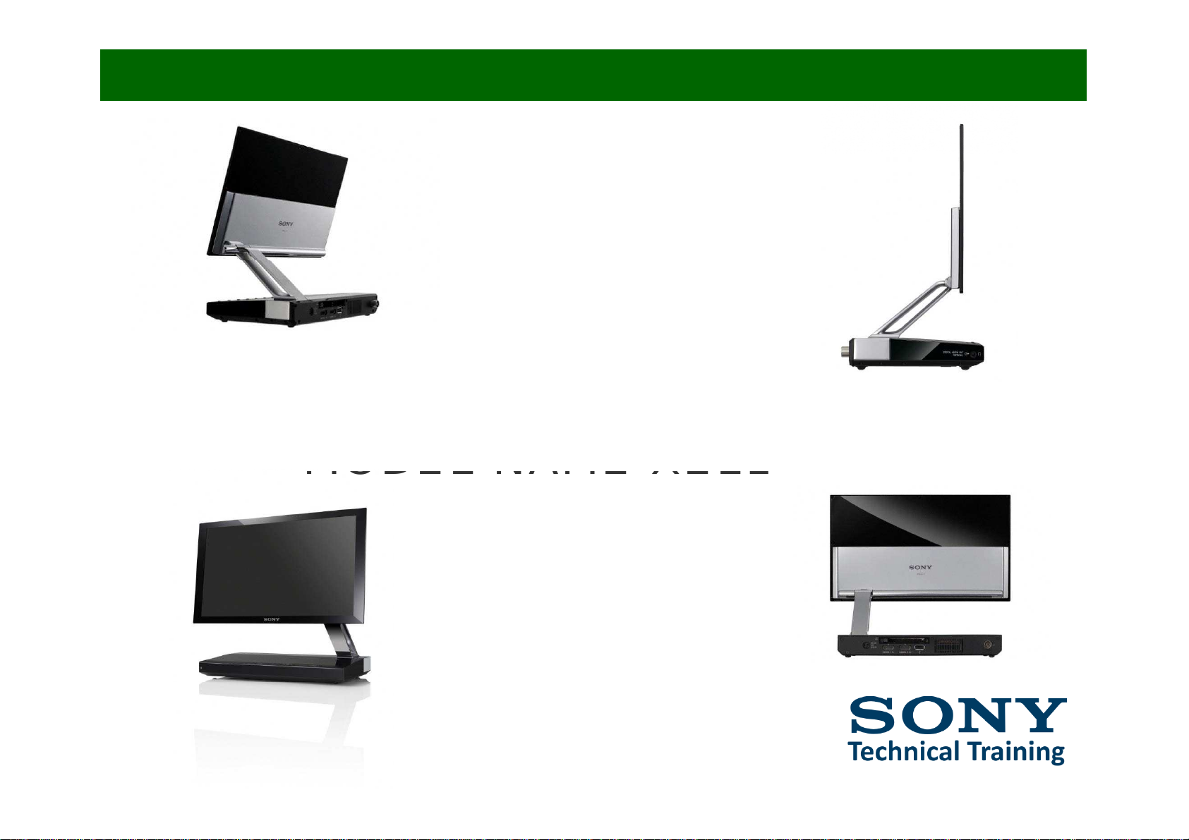
FL1E OLED TV chassis
MODEL NAME XEL1
Page 2

TABLE OF CONTENTS
Page
I. INTRODUCTION
2. FEATURES
4
2.1
C
omparison:
FL1E
vs.
SE3
2.2 Thickness
2.3 Contrast / Response Time
2.4 Super Top Emission
5
7
8
9
10
14
17
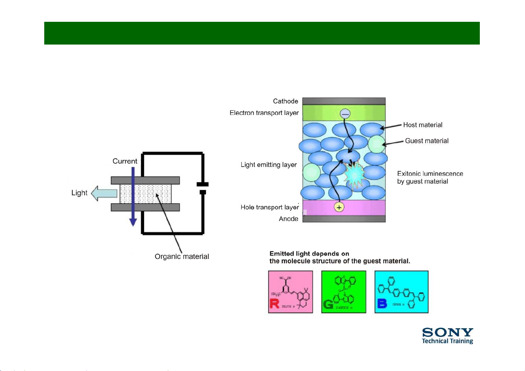
3. BACKGROUND / TYPES
3.1 Principles behind OLED
3.2 Types
3.3 Facts
19
20
25
4. FEATURES INTO DETAIL
4.1 Panel Structure
4.2 Super Top Emission
4.3 Response Time
26
28
29
30
33
4.4 Sound System
4.5 High Contrast
4.6 Auto Brightness Control
4.7 Bioplastics
4.8 Buttons and Connections
35
36
37
38
4.9 Audio Out Digital
4.10 Specifications
4.11 DVB-C Support
4.12 Operating Instructions
Page 3

5. SERVICE STRATEGY
Page
40
42
44
45
5.I Mechanical Structure
5.2 Repair Flow
5.3 Error Codes
5.4 Block Diagram
6. PANEL DEFECTS
46
48
5.5 Overview
6.I Bright Dot
49
51
52
6.2 Black Dot
6.3 Panel Protection
7. MODULE EXCHANGE REPORT
56
8. SOFTWARE UPDATES
Page 4
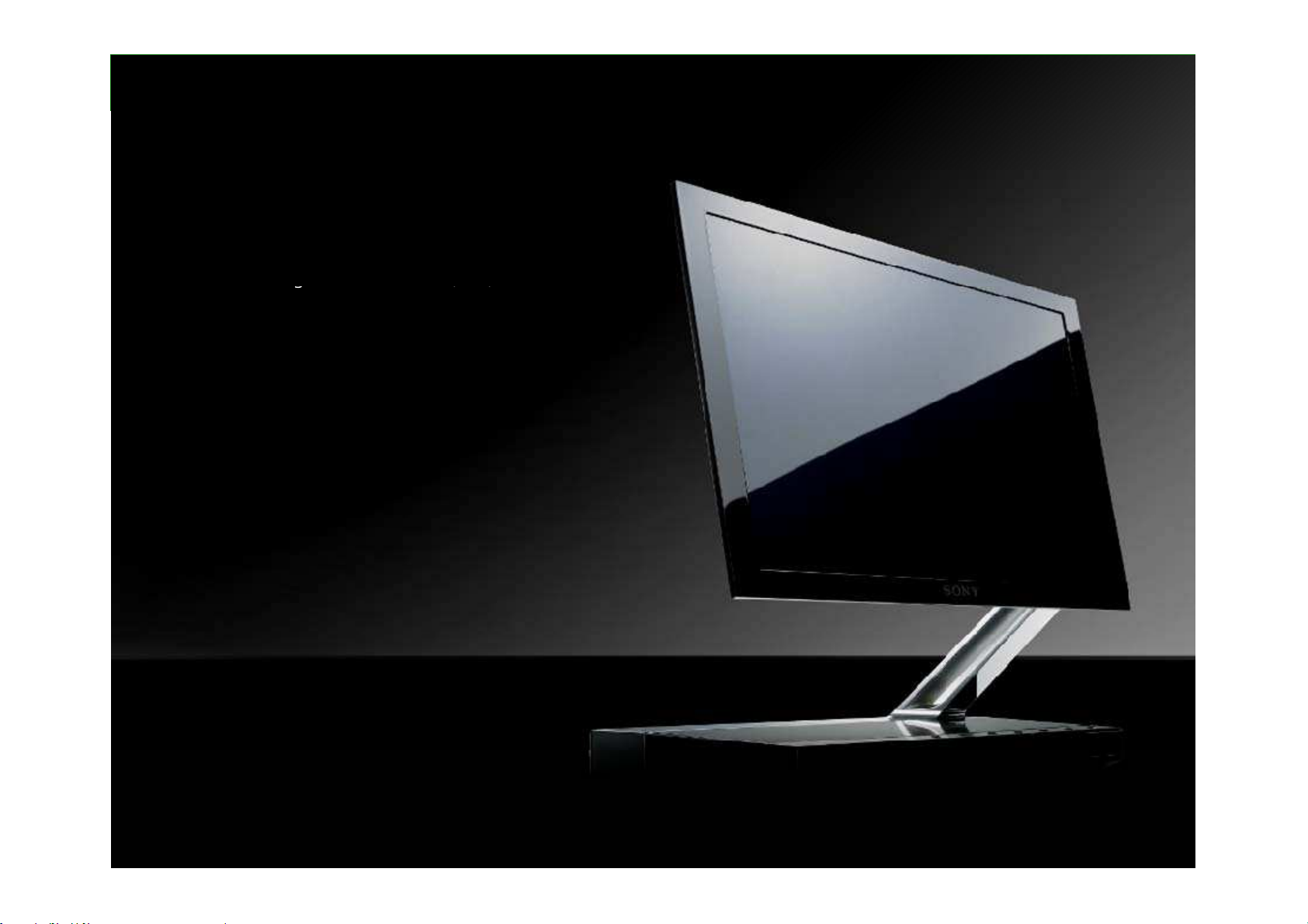
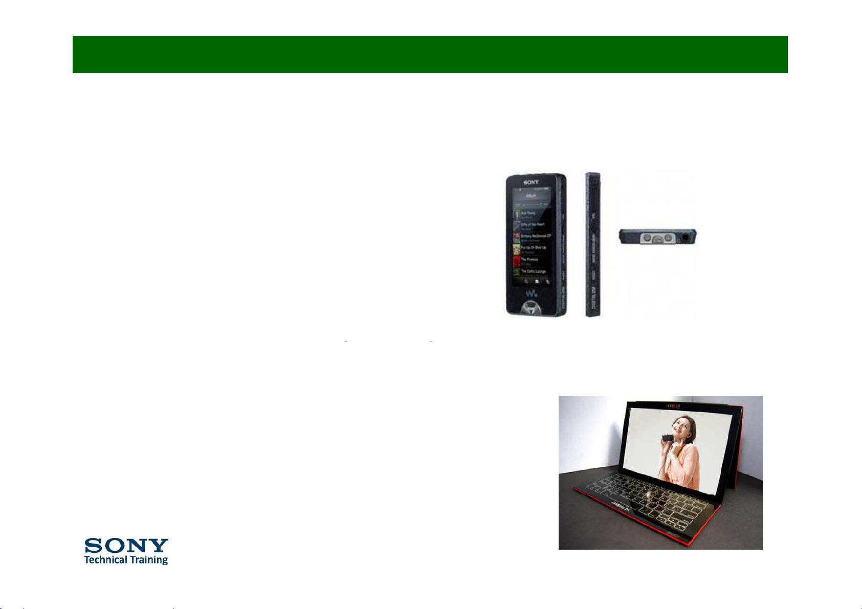
XEL-1: First OLED TV in Europe
OLED High Picture Qualit
y
v
11” SONY OLED Panel
Ô
960×540dots
Õ
v
Absolute High Picture Quality
-Outstanding Contrast ÔOver 1,000,000:1
Õ
g
,,
- Brazing F ast R esponse Time
- Wide Viewing Angle
- Peak Brightness
- Exceptional Colour Reproduction
v
OLED Fine Motion*
Sound
v
Screen Position Sound System
with Screen Frame Tweeter*
Slim & Stylish Desig
n
v
“Lightness” by Cantilever Arm
v
Amazing Slim
ECO Friendl
y
v
Light Emission Control*
v
Bio-plastic for Remote & Rear cover*
V
arious Connectivit
y
v
HDMI×2
v
USB×1 with Photo application
* = Exclusive features for XEL-1 Europe
Ý
Page 5
Feature Comparison: FL1E vs. SE3 (EG1L)
•
F
eatures
Added
9 Auto Brightness Control
9
Orbit
Control (picture moves all 30 minutes as PDP)
9 Screen Saver
9 Optical/HP compatible jack
9 New Speaker System
• Features Changed
9 Panel Resolution (graphics & video 960 x 540
)
RM-ED015
(g p )
9 Picture Mode (cinema > custom & settings)
9 Sound Effect (settings)
9 Audio Maximum Output (1.2W)
Lithium batter
y
CR2032
9
T
oneContro
l
9 Remote Control
Page 6

Feature Comparison: FL1E vs. SE3 (EG1L)
•
F
eatures
Del
ete
d
9 Inputs: composite / component / scart2 / audio / PC / HDMI audio
9
Outputs:
Video
/ Audio
9 Backlight at picture menu
9 Clear Voice & BBE ViVa at Sound effects
9 Logo illumination
9
PC S
ettings
9 PAP / PIP / Freeze
9 Syncronized Recording
9 Bravia Theatre S
y
nc
y
9 Picture Frame Mode
9 Hotel Mode
9 Demo Mode
Page 7
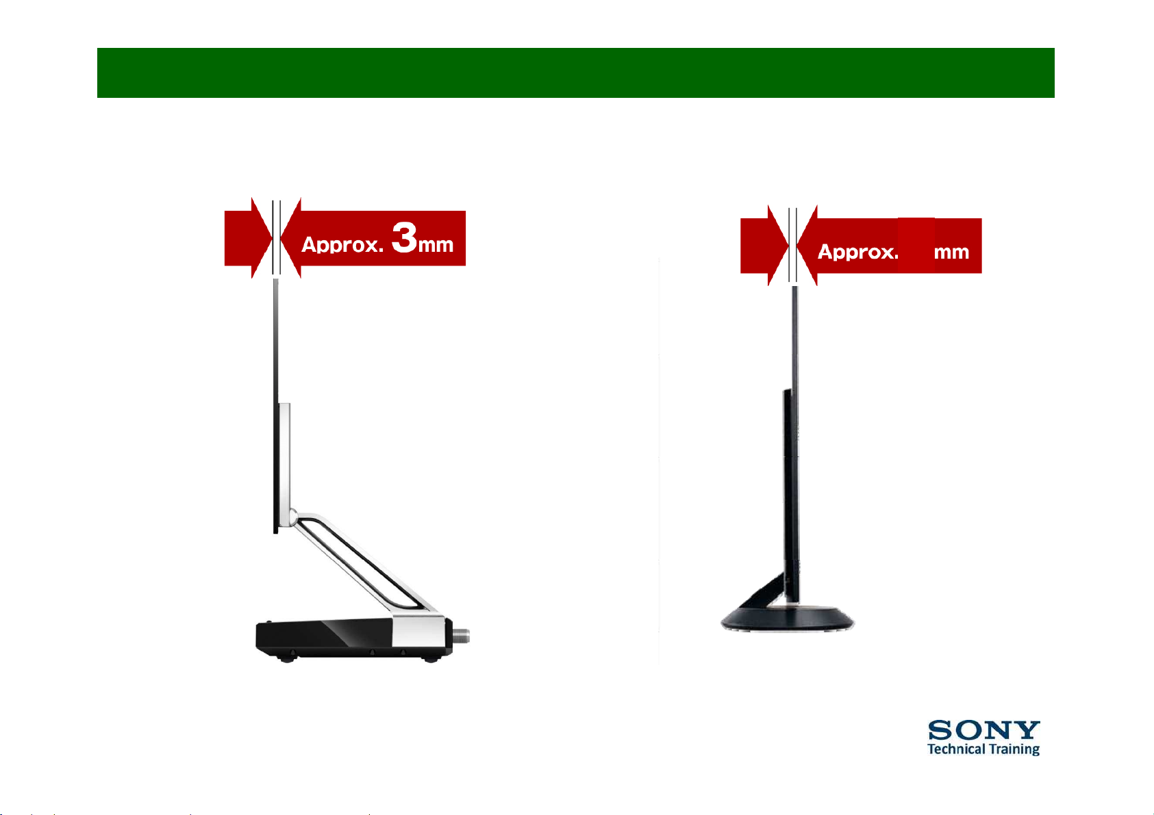
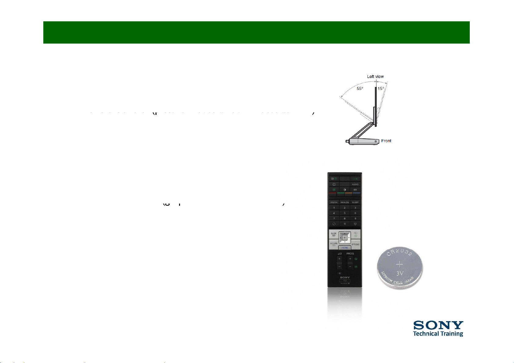
Thickness
(Thinnest Part)
9
XEL1 KDL-40ZX1
Page 8
Contrast / Response Time
Conventional TV OLED TV
High contrast
The OLED display technology keeps the
luminous phenomenon under perfect
control. The result is striking
reproducibility of black levels and sharp
ima
g
eswith high contrast.
g
g
Response time
The OLED pixels emit light directly. This
results in a nearly instant response time,
an ideal display property fo
r
w
atching
fast-pacedmovementssuchasfootball
game play.
Wid
eviewing angle
Enjoy motion pictures from any angle.
Page 9
Super Top Emission
Conventional TV OLED TV
High brightness
The top emission structure intensifies
bright
nessbyincreasingtheaperture
ratio.
Wid
ecolourrange
The combination of colour filters and the
microcavity structure widens the colour
gamut.
Page 10
•
Principle behind OLED (1/4)
An OLED consists of the following parts:
ƒ Substrate (clear plastic, glass, foil) => supports the OLED
ƒ Anode (transparent) => removes electrons (adds electron holes) when a
current flows throu
g
h the device
g
ƒ Organic layers => layers are made of organic molecules or polymers
• Conducting layer transports ‘holes’ from anode
• Emissive layer transports electrons from the cathode
ƒ Cathode (may or may not betransparent) => inject electronswhen a current
flows through the device.
Page 11
Principle behind OLED (2/4)
•
How do OLEDs emit light?
ƒ A power supply applies a voltage across the OLED
ƒ An electrical current flows from the cathode to the anode through the organic
layers
(
actually
this is a flow of electrons)
• The cathode gives electrons to the emissive
layers of organic molecules
• The anode removes electrons from the
conductive
layer or
organic
molecules
(this is in fact giving electron holes to
the conductive layer)
ƒ Electrons find electron ‘holes’
at the boundary between the
emissive and the conductive layer, then falling into an energy level of the atom
that is missing an electron.
ƒ The OLED emits light
ƒ The colour of the light depends on the type of organic molecules
ƒ The intensityor brightness depends on the amount of electrical current
applied.
Page 12
Principle behind OLED (3/4)
OLED
=
O
rganic
L
ight
E
mitting
D
iode
Page 13
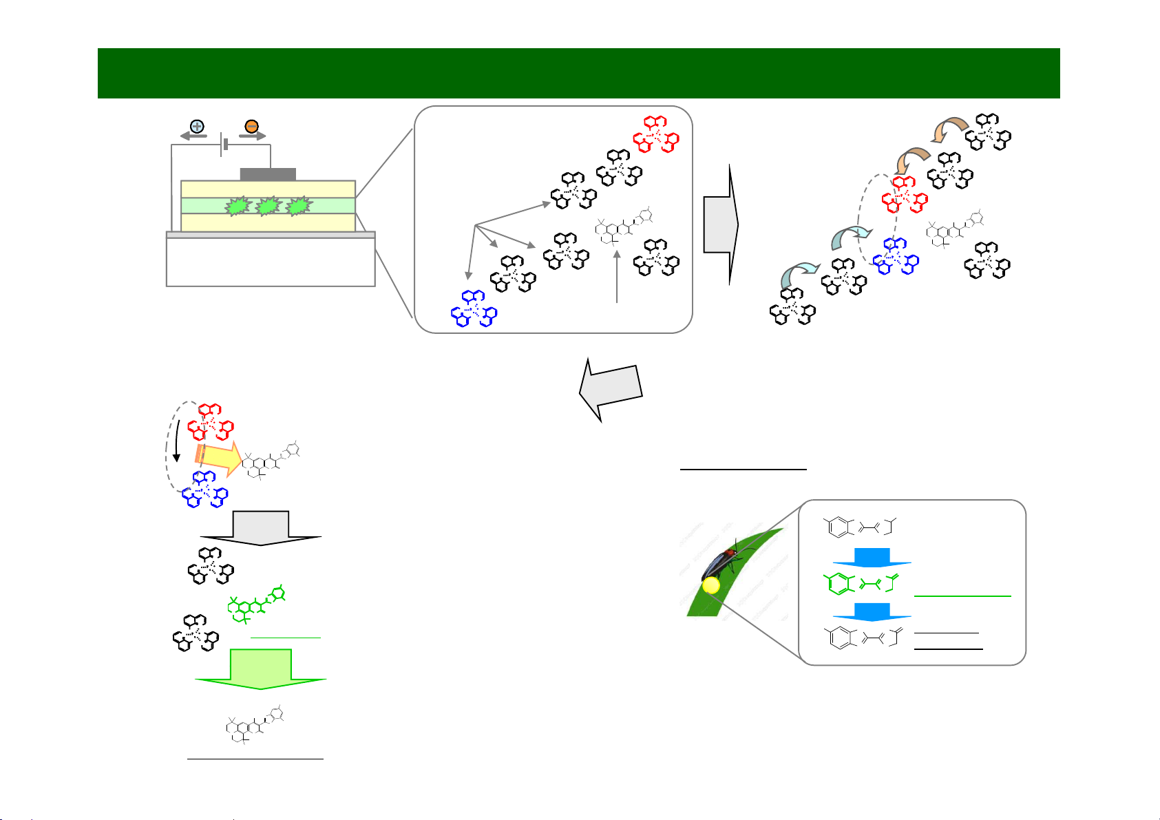
N
O
AlNN
O
O
Ù
N
O
AlNN
O
O
Principle behind OLED (4/4)
N
O
O
O
S
N
R
R
N
R'
O
N
O
AlNN
O
O
N
O
AlNN
O
O
Host molecules
ETL
EML
HTL
Cathode
Electron transport layer
Emissive layer
Hole transport layer
Anode
N
O
AlNN
O
O
Ù
N
×
O
S
N
R
R
N
R'
O
N
O
AlNN
O
O
Electron / Hole Pairing
A
lNN
O
N
O
AlNN
O
O
×
N
O
AlNN
O
O
N
O
Al
N
N
O
O
Guest molecules
nü
Glass board
N
O
AlNN
O
O
N
O
AlNN
O
O
O
Al
N
N
O
O
N
O
AlNN
O
O
1. Electrical charge in emissive layer
Electrons and holes are injected into the emissive
layer from electrodes.
2. The formation of electron-hole pairs
th
rough charge transfe
r
Electron-hole pairs are formed when the injected
electrons and holes approach one another while flowing
through the emissive layer on host molecules.
3. Energy transfer to the emitting
N
R
R
R'
N
O
AlNN
O
O
Ù
Energy transfer
Recombine
Fig. Luminescence of fireflies (emission of luciferin oxide)
Bioluminescence
material (guest molecules)
When electrons and holes recombine in
electron-hole pairs, energy is transferred to
the guest molecules.
OSNO
N
O
AlNN
O
O
×
N
N
S
N
S
HO
COOH
Oxidize
Luciferin
Emit
4. Excitation of the emitting
material (guest molecules)
Guest molecules are excited by energy
transferred from recombining electrons and
holes, achieving a state of high energy.
O
S
N
R
R
N
R'
O
O
Al
N
N
O
O
N
O
AlNN
O
O
Excited state
N
S
N
S
HO
O
Low-energy
ground state
Light
N
S
N
S
HO
O
Oxidized Luciferin
ÔExcited stateÕ
Light
Some insects and other organisms produce organic matter to emit
light, but the principle of this luminescence is somewhat different
from that of an OLED. An OLED produces light with an electric
current, while bioluminescent organisms generally produce light
through a chemical reaction (oxidation).
The excited guest molecules emit light, thereby
releasing energy and returning to their lowenergy ground state
O
S
N
R
R
N
R'
O
Low-energy ground state
Page 14
Types (1/3)
ƒ 1. Passive-matrix OLED (PMOLED)
- Have strips of cathode, organic layers and strips of anode
These strips are arranged perpendicular, at the intersections of the cathode and
anode. The ‘pixels’ light-up when a current is applied.
-Use
d
for
text an
d
i
cons on smallscreen
(PDA, mobile phone, MP3 players).
ƒ 2. Active-matrix OLED (AMOLED
)
()
- Have full layers of cathode, organic molecules and anode, but the anode layer
overlays a thin film transistor (TFT) array that forms a matrix.
- Used for computer monitors, TVs and electronic signs.
Page 15
ƒ 3. Transparent OLED (TOLED)
Types (2/3)
- Have only transparent components (anode, cathode, substrate).
Turned off, they are up to 85% transparent.
- Used for heads-up displays.
ƒ 4. Top-emitting OLED
- Best suited for active-matrix desi
g
n.
g
- Used for TV screens.
Page 16
ƒ 5. Foldable OLED (FOLED)
Types (3/3)
Have substrates made of very flexible foils or plastics.
ƒ 6. White OLED (WOLED)
- Emit white light that is brighter and more energy efficient
than that emitted by fluorescent lights.
- Used for lighting homes and buildings.
Page 17
Facts about OLED (1/2)
ƒ Thinner, lighter and more flexible than LCD.
ƒ Brighter than LEDs, because the organic layers of an OLED are much thinner than
the corresponding inorganic crystal layers of LCD.
ƒ Do not require backlighting like LCDs and they consume much less power.
This is veryimportant for battery-operated devices.
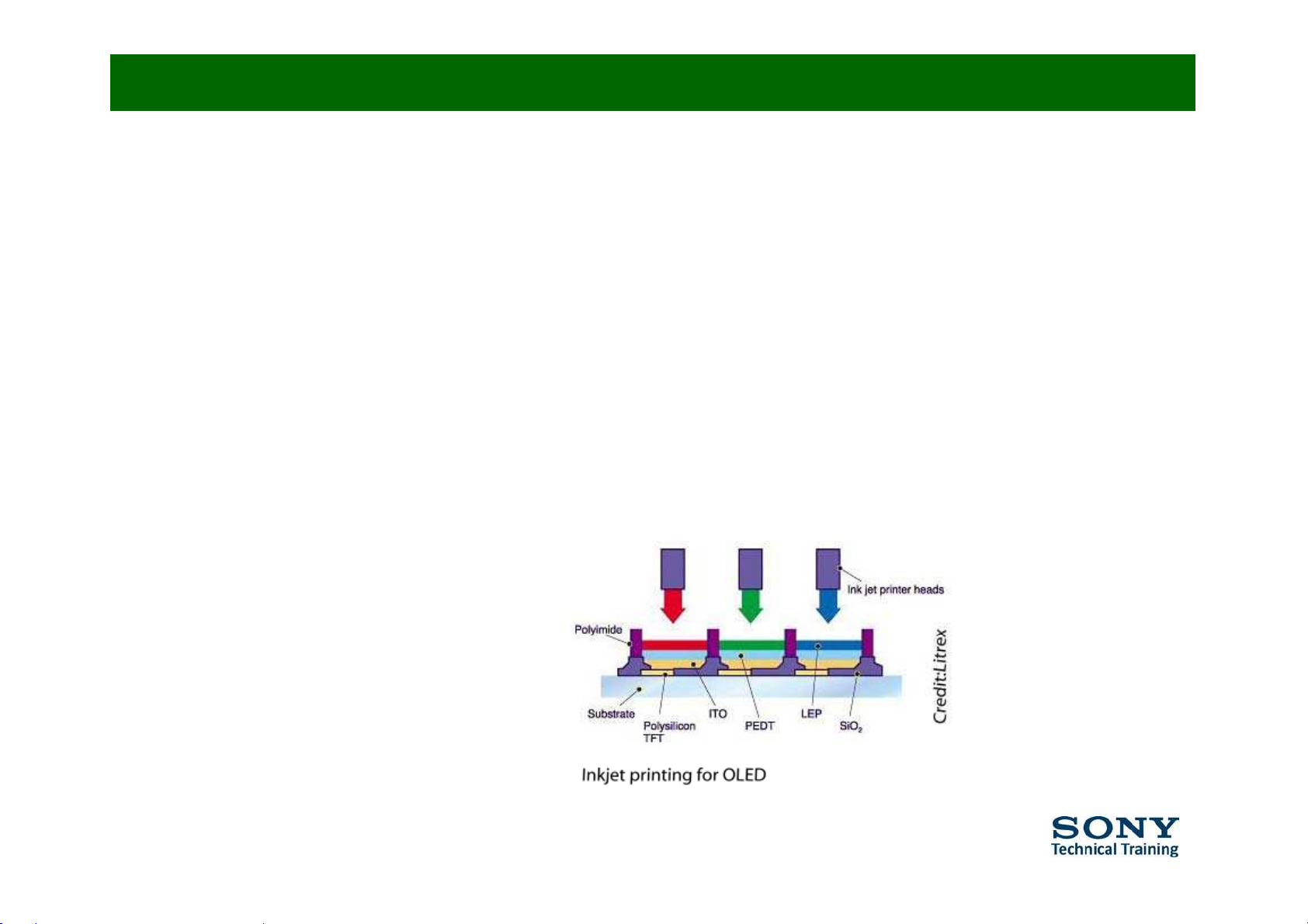
ƒ Easier to produce and can be made to larger sizes. (printing process)
ƒ Wider viewing angle.
Page 18
ƒ Lifetime: While red and green OLED films have
Facts (2/2)
ƒ longer lifetimes, blue organics currently have
ƒ much shorter lifetimes.
ƒ
Manufacturing
:
Expensive
right
now
(
low
volumes, unique
set
-up)
.
ƒ
W
ater:
OLED
sare afraidof water.
Page 19

Panel Stucture
OLED
panel rearview
T2 board
Page 20
Sony’s unique Super Top Emission
Super Top Emission (1/5)
yq
p
p
technology promises higher brightness and
a wider gamut of colour
•
The top emission structure (light emits from the upper side of the organic
film) renders images with higher brightness and efficiency.
• The microcavity structure widens the range of colour reproduction.
Conventional panels display by ‘bottom emission’, a method in which light exits from an organic layer
• Colour filters reduce the reflection (glare) of ambient light and intensify
the purity of colour.
through a transparent anode. To integrate the OLED, a controlled circuit has to be arranged under
the anode in a configuration that decreases the aperture ratio as the OLED emits light from the
anode. Sony solved the problem by adopting a top-emission construction in which the controlled
circuit is arranged over the anode instead of under it. The resulting increase in the aperture ratio
intensifies the brightness and improves efficiency
.
The microcavity structure helps to improve the colour reproducibility.The film thicknesses of red,
green, and blue are selected to match the optical path lengths between the cathode and anode
electrodes to the peak EL spectral wave lengths for the respective colours.
The circular polarizer, the device typically used to cut ambient reflected light, decreases the image
brightness. The OLED avoids the problem by using colourfilters to cut the ambient reflected light.
This widens the gamut of colour while minimizing brightness degradation.
Page 21

Super Top Emission (2/5)
Page 22

Super Top Emission (3/5)
Micro Cavit
y
y
Page 23

Super Top Emission (4/5)
S
uper Top
E
mission vs.
N
orma
l T
op
E
mission
Super Top Emission
Normal Top Emission
colour filter
Polarizing film
Retardation film
Glass substrate
Cathode
Organic film
Anode
Cathode
Organic film
Anode
Glass substrate
TFT
TFT
OLED×Microcavity×colour filter OLED×Retardation film×Polarizing film
Glass substrate
Glass substrate
Oled106.jpg
oled105.jpg
To complement the gains in brightness and efficiency from the top emission structure,
Super Top Emission cuts the ambient reflected light and widens the colour range
by adopting a microcavity structure and colour filters.
Page 24

Super Top Emission (5/5)
Wide
Colour
Gamut
Page 25

Response Time
Outstanding Motion Picture Expression
The OLED display has an excellent response time because the organic elements
emit light (output) only when current is flowing (input). There is no delay in
output due to molecular motion, as wit
h liquid
crystal, and no afterglow from
phosphors, as with CRT. Therefore, the display produces sharp pictures with
clear and natural motion. The dynamic characteristics of the display are stable in
both high
-
temperature and low
-
temperature environments
.
Comparison of video images
Dynamic Characteristics in Relation to the
Ambient Temperature*
Dynamic
characteristics of
the OLED display
remain remarkably
stable under both
high-temperature
OLED display
An example of motion blur
LCD(60Hz)
oving Picture
erformance
Slow
an
d l
owtemperature
conditions
2
1.021.0
0102030
40
LCD(120Hz)
OLED 60Hz (duty30%)
M
P
First
ss
Test cell response
0
0.5
ç»Î
10ôsec
0
0.5
ç»Î
10ôsec
Brightn
e
RT=0.01
ms
Page 26

2.3mm Thick Multilayer Piezoelectric Actuato
r
I
Embedded in the
Sound System (1/2)
y
(2kHz > 20 kHz / 0.2W+0.2W)
frame of the panel
>> No change in
appearance !!
Base Unit Shape
3
=> Extended
to the
f
ront.
=> Thickened only at the back.
New Speaker Box
2
2 mm
(120Hz > 8kHz / 1.2W+1.2W)
8
mm
Page 27

<Current>
Sound System (2/2)
<New>
Sound is coming from the
Panel !!
Speaker Box
Sound Flow
(
400Hz
> 15kHz / 1W+1W)
wow!!
Not enough Bass sound,,,
Reflected on
the back of the
pane
l
Fatal,,,
Not coming to the front,,,,
Page 28

High Contrast
• Peak Brightness : 500cd/m² over (Vivid)
– All White Picture : 150cd/m²
• Black is out of range of the equipment to measure
–
1,000,000 : 1
contrast
”
BRAVIA20”
OLED
11
Page 29

Auto Brightness Control
Function and example
v Detect the higher brightness level and position
v Control brightness level as follows
Ste
p
1: Reduce Brightness for all screen area
p
g
Step 2: Reduce Brightness for partial area
(ex. press red LOGO)
Detect Brightness level
Reduce Brightness all area, later on partial area
Instruction Manual is saying:
Page 30

Bioplastics (1/3)
89% of
customers are intereste
d in “
eco-frien
dly”
products
and 30% actively look for them.
Information Resources, Inc.2007
XEL-1 is the
world’s first TV
to use
“
Bi
oplas
ti
cs
”
on Remote Control and Terminal Cover
Page 31

Bioplastics (2/3)
Molding
with additives
What is it?
Plastics
(PLA, PA11, etc)
Fermentation /
Chemical
p
rocess
Sony
Product s
Recycling
p
Biomass
Incineration
CO
2
Photosynthesis
H2O
etc
Page 32

Bioplastics (3/3)
Remot e contr ol
Which part is
bioplastic
?
Terminal cover
Page 33

Buttons and connections (1/2)
Page 34
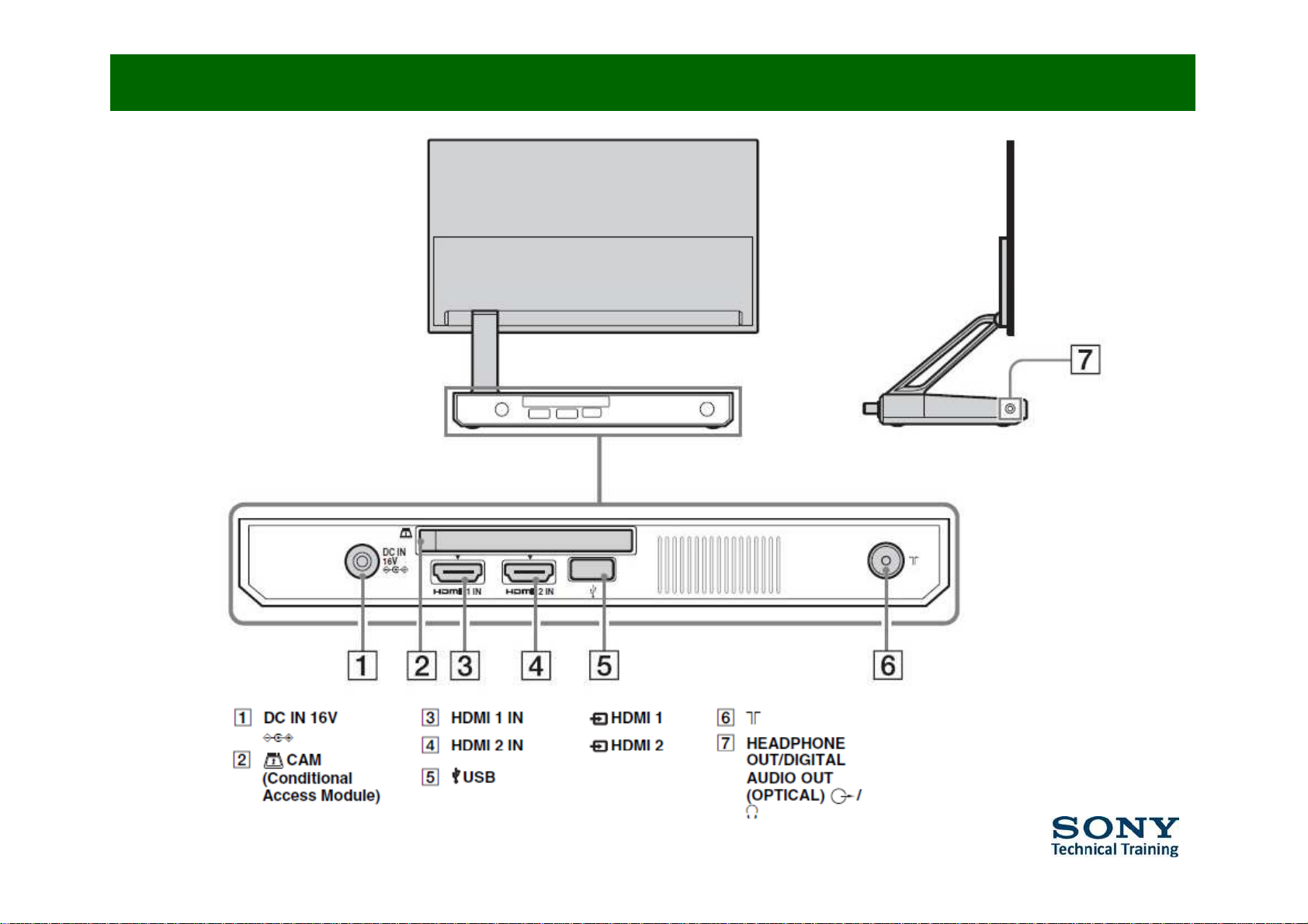
Buttons and connections (2/2)
Page 35

Audio Out digital
Page 36

Specifications
Page 37

DVB-C support
http://support.sony-europe.com/TV/DVBC/
Page 38

Operating instructions
http://support.sony-europe.com/manuals/
Page 39

Service Strategy
Page 40

Mechanical Structure (1/2)
Display module
Arm module
Chassis/Pedestal module
Page 41

Mechanical Structure (2/2)
SP BOX(L)
HE1 PWB
CAM slot/SP BOX Amp
HE2 PWB
SP BOX(R)
Front Keys, LED, HP/OPT jack
FAN
-
Unit
(with Heat spreader)
DC
PCMCIA
BE PWB
RF
HDMI x2
USB x1
System devices
Page 42

Repair Flow
1.
Check the claim
2. Exchanging the module & the boards
• Check LED blinks
•
AC ad
apto
r
• Panel module
• Boards (BE, HE1, HE2)
• Connections among the boards
3. Software update
•
Check the S/W Version
• Update S/W
4. Confirm general functions
Page 43

Flow Chart for repairing
Repairing starts
Power On
the TV
Make sure to press
Power on t he f ront
p
anel
Open the chassis an
d
Power
ON?
Exchange the
other A C
ada
p
tor
Power
ON?
Get n ew
AC
p
check if
F6204
is o pe
n
or not
Wait for 20 sec to
check if Stby(RED)
;GU
0
Q
;GU
0
Q
adaptor
to
exchange
LED blinks or not
LED
Check if the customers
claims the panels
Panel
After checking the
cosmetic qualities,try
to
re
p
roduce the
Images on
0Q 0Q 0Q
bli nk s?
qua
liti
es or no
t
qualities?
Check
PANEL
qualities
p
symptons
the panel?
;GU
;GU
;GU
Blinking times
are
16,23,24,25,26,
28?
Dis-assemble the TV and exchange
BO ARDs
to the other to chec k if the
sympton would be c hanged or not
0Q
When exchanging
BE board,pay
at t ent ions on the
connections
Dis-assemble
PANEL mo dule
and exchange
to the other t o check if the sympton w ould be
changed or not
;GU
Page 44

Error codes
LED Blink FL1E Note
2 DC DET (Main Voltage
)
To be Error-STBY
LED Blink FL1E Note
15 Tuner Erro
r
• Red digits: Related to Panel module
_
(g)
3 Irregular AC Adapter Error To be Error-STBY
4 Reserved
5 Reserved
16 Panel Micro Error To be Error-STBY
17 I2C CH0 (VERD NVM/RTC)
18 Digital Demod.
6 Reserved
7 Internal Temperature Error
8 Audio Error (SP Protection) To be Error-STBY
19
USB Error
20 CI Error
21 VCT Error
22 MSP-S Error
9
FAN Error
To be Error
-
STBY
10 Digital Error
11 NVM Error
12 I2C Error VCT Reboot TV
23 Panel FPGA Erro
r
To be Error-STBY
24 Panel Current Error To be Error-STBY
25 Panel Voltage Error To be Error-STBY
26 Panel Temperature Error To be Error-STBY
13 Reserved
14 HDMI Error
27 FRC-M Error
28 Panel V Sync Error To be Error-STBY
Page 45

FL1E Block diagram
Digital Video
Analog Video
Digital Audio
Analog Audio
Graphics
Control
BE Board
Piezo Speaker
VCT-Premium
FRC-M
Panel
UFE
DDR2
512M
667
RF IN
Digital
Analog
CVBS Analog RF
333M
333M
DDR2
512M
667
DDR2
256M
667
DDR2
256M
667
333M333M
DDR2
256M
667
SW
I2C
T2 Board
Firmware
NVM
I2C
EMMA3SL
MPEG/AVC
Decoder
AV/Switch
colour Decoder
3D Comb
PC/HD ADC
Audio Dig Decoder
Audio Delay
Scaler
NR
1.5HFR
60 > 90Hz
50 > 75Hz
MC
Graphics Mix
FPGA
Gamma/WB
Control
NAND
Flash
Digital Video[0-7]/Clk/HS/VS
Graphics ARGB[0:7]CLUT
Around 30M /CLK/HS/VS
Graphics CLK
I2S Digital Audio
QSS
LVDS
TS from
COFDM/QA
M
EMMA3 SPDIF
I2C
RSDS
M
LVD
S
MSP5651S
I2
USB
Photo
MS (JIG)
Histogram
TV Control
TXT Decoding
HDMI Decoder
WCG
Panel
Micro
TMDS
I2C
UART
I2
C
VCTP
I2C
I2C
I2C
M
PEQ
Delay
HPF/LPF
S
TAS5103
PW
M
I2C I2C
HDMI1
HDMI2
Sub Micro
Power SW
Key
STBY
NVM
TMDS
Analog
Audio
Main L/R
EDID
NVM
SW
T
emp
sensor
NVM
VCTP SPDIF
EDID
NVM
FAN
FAN
PWM
M
AD
IR
LED
NVM
RTC
HP
Amp
HE1 Board
SIRCS
OPT
sensor
I2C
+6dB
Amp
Analog
Audio
HP L/R
SPDIF
OUT
Main
Speaker
HE2 Board
OPTICAL
Headphone out
PCI
PCMCIA
Connector
CI
buffer
TPA3005D2
L /1W
R/ 1W
Page 46

Overview
ƒ Tuner BTD-HF413
• Analogue + DVB-T + DVB-C
ƒ IC 8200 Î FRC9459M
• Frame rate control
ƒ IC 7000 Î UPD61300
•
EMMA 3 processor
also
used
in EG1L (W4000)
ƒ IC 4701 Î VCT8398P
• Video processor also used in EG1LL (L4000)
ƒ IC 3405 Î MSP5661S
ƒ Sound processor
ƒ
IC 3401
Î
TAS5103
ƒ Digital Amplifier
ƒ
IC 040 (HE1
board
)
Î
TPA3005
ƒ Class D amplifier
Page 47

Panel defects
Page 48

Bright Dot
One or more pixels are always shining. This means the pixel is in out-of-control mode.
You can recognize it when the screen is black, e.g. with HDMI input without signal.
Green Bright Dot
Red Bright Dot Blue Bright Dot
Page 49

Black Dot
Black Dot is caused by a pixel
having a
colour
dot not shining
at all
.
In case the background colour is the same as that of the defective pixel, it looks black.
In case the background is all white, an other colour can be noticed.
Green Black Dot
Visual image of RGB Black Dot
Blue Black Dot Red Black Dot
Same
colour
as background
All
white
Screen
No green pixel
can be seen =>
Magenta
No blue pixel
can be seen =>
Yellow
No red pixel
can be seen =>
Cyan
Page 50

Dot Chart
Claim
How to classify as “Bright Dot”?
Instruction
Manual is saying:
Bright Dot?
Y
es
No
Judge : NG
Send complete
set to BCN
Explain the customer it is a panel defect.
Then send set to BCN for panel exchange.
Judge : OK, Explain customer it is NOT a defectJudge : OK, Explain customer it is NOT a defect
Change the input to HDMI without
signal. If it is noticeable in all black
screen, it is a bright dot.
Black Dot?
OLED panel is high-precise device. Dot defect may be recognized on the screen
as described in the Instruction manual. Sony only releases products that have been
strictly inspected and judged as good products at the factory.
Details of the specification are confidential.
OLED panel is high-precise device. Dot defect may be recognized on the screen
as described in the Instruction manual. Sony only releases products that have been
strictly inspected and judged as good products at the factory.
Details of the specification are confidential.
Did
customer
understand
?
Yes
Completion of
customer
treatment
No
Customer is still Not satisfied
Set exchange
A
rrange one set to exchange.
Explain to the customer that another set may have black dots again.
Y
es
Completion of
customer
Did
customer
understand
Accept to return
the TV
No
Customer still complains
Explain the customer that Sony accepts to return (customer refunded)
treatment
?
Page 51

XEL-1 Screen Saver
Example of Screen
Panel Protections
A few minutes
*60 min.
nAuto Startup Seq.
nRadio (UK)
nPhoto
nPhoto Thumbnail
nPhoto Slide Show
How to
return
Photo
(Original) Photo
Black Screen ×XEL-1 logo
Press
A few sec.
nTe l e t ex t
nEPG
nStill / Almost Still Image
(RF & HDMI)
Brightness Reduction (incl. Auto Brightness Control Function)
Home / OPTIONS
*
30 mi
n.
nXMB/OPTION
Still/Almost still Image
Darker than the original image Image Brightness (Original)
Time-out Screen Saver
A few minutes
n
MENU
Released OSD to be shown permanentl
y
(Original) Screen
XMB
A few minutes
nMUTE
nUnsupported signal
py
MUTE
MUTE
MUTE message Disappea
r
MUTE message
Orbit
Picture position moves each 30 minutes.
nOrbit was introduced
in PDP
Page 52

Module Exchange Report (1/4)
• Module Exchange tool used
to return complete product.
• Existing tool used by all
ASCs.
• Familiar “Look & feel”, even
though repair policy is
different.
52
Page 53

Module Exchange Report (2/4)
•Important Guideline Data
p
Page 54

Module Exchange Report (3/4)
• It is essential to add the return
address and contact details for
the repaired OLED set.
• Without accurate data, BCN
cannot meet TAT requirements.
• Return address can be ASC or
SCO depending on your choice.
• Not to be used for end user
address.
54
Page 55

Module Exchange Report (4/4)
• Output form is standard.
• Form MUST be included with the return
of the defective shipment.
55
Page 56

Service Mode (1/3)
• Prepare remote commanders
- TT R/C
-
RM-E0015 has
no TT Command key on it.
Y
ou have to prepare
Normal R/C
•Press
- T>T> Home (TT R/C)
-
+
pp
another one for TT.
In STBY mode, display> 5>
Vol
>
Stby
(Normal R/C)
• TV will enter into Service mode.
<Useful TT commands List>
TT08 >> Go back to Shipping condition
TT13 >>Disable/Enable Still Detection/AutoBrightnessControl
TT33 >>Disable WP to write EDID data (HDMI)
TT47 >>Mute BOX SP(to check Panel SP only)
Page 57

Service Mode (2/3)
• Select “PRODUCT VERSION” and press the right arrow key. The software versions
will appear.
• There are 4 microcomputers in XEL-1. Each of them has its own software version
Software versions
ind
ependently.
– TM: TV Micro (VCTP)
– VM: Standby Micro (VERD)
– DM: Digital Micro (EMMA)
–
PM: Panel Micr
o
– Software versions will always be informed to Service as “PKG VERSION”, not as individual files.
Press key
Page 58

Service Mode (3/3)
• Select “ERRORS” and Press Right Arrow key, then ERROR Status appear.
ERROR status
P
ress
key
Page 59

Software Updates
Preparation
Open the service terminal cover (Fig.1)
Bottom of the set
Open the service terminal cover
How to Update Software
1. Unzip the MS_PKG release file and save the fl1e folder onto a MS.
Connect flexible Cable 1 to BEJIG Board (Fig.2)
(Cable 2 is not required for a software update)
Cable-2 is not required for a
software update
2. Unplug power to turn TV Power Off.
3. Insert the MS into the MS slot in BE-JIG board.
4. Plug the power cord to power on the TV.
Process takes around 30 secs to start. If TV is in analogue
mode,
p
icture
is
displayed, but this is normal.
6. During MS download STANDBY (RED) LED is on and TIMER (ORANGE)
LED is blinking (common behavior across all chassis).
7. When MS download is finished (took more than 10 min). the following
Fig.1
LEDs are displayed:
STANDBY (RED) / TIMER (ORANGE) / POWER (GREEN)
8. Power off the TV.
9. Disconnect the cable from TV.
Cable-2 is not required for a
software update
10. Plug the power.
11. (If MS package does not include a VCTP update, ignore this step)
STANDBY (RED) LED is lighting about 5 seconds (VCTP is rewriting NVM).
There will not be a picture in the panel, so unplug and plug the power
supply again.
12. Check the PKG version in the Service Menu.
Fig.2
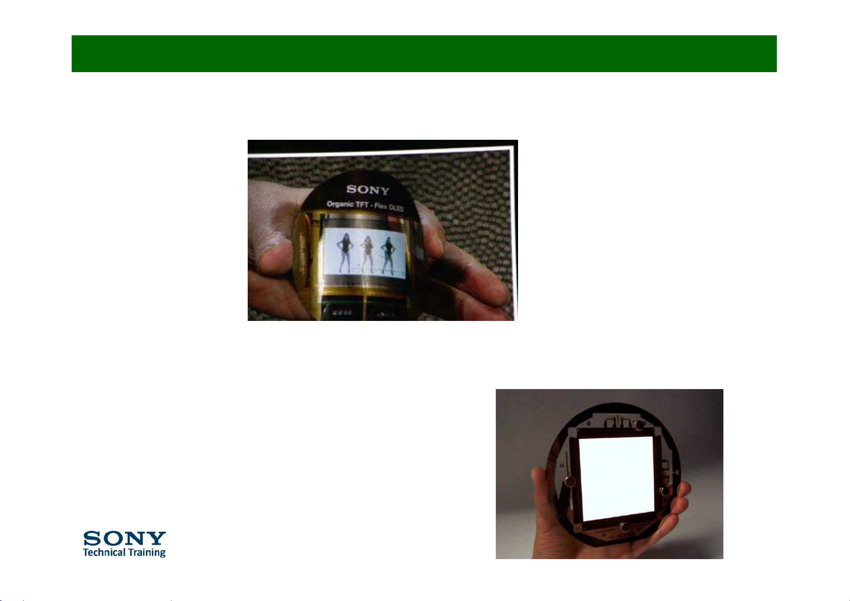
Page 60

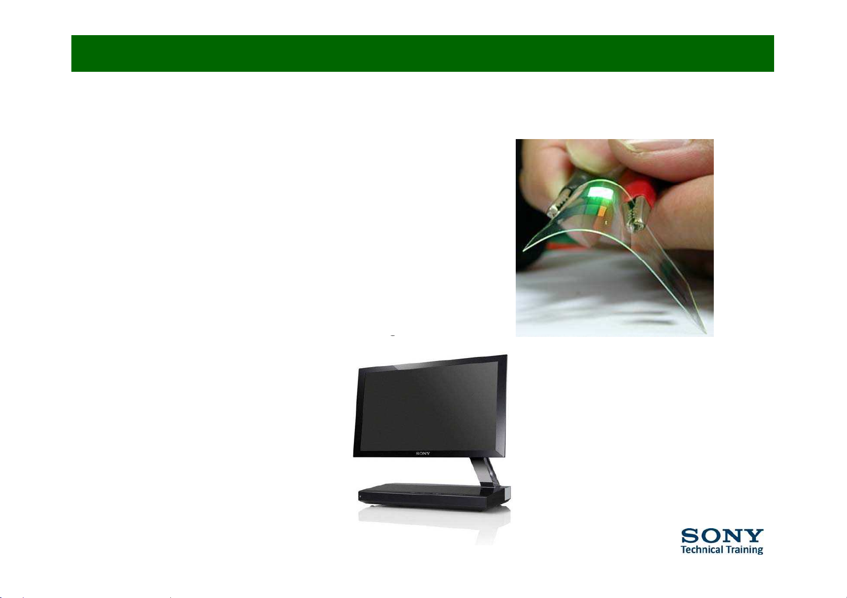
Future developments
”
21 Prototype OLED
 Loading...