

Sony XDS-PD1000, XDS-PD2000 User Manual

PROFESSIONAL MEDIA STATION
XDS-PD1000
XDS-PD2000
OPERATION MANUAL [English]
1st Edition

WARNING
To reduce the risk of fire or electric shock,
do not expose this apparatus to rain or
moisture.
To avoid electrical shock, do not open the
cabinet. Refer servicing to qualified
personnel only.
3. Internal air ambient temperature of the rack
When this product is installed in a rack, please make sure
that the internal air ambient temperature of the rack is within
the specified limit of this product.
4. Prevention against achieving hazardous condition due
to uneven mechanical loading
When this product is installed in a rack, please make sure
that the rack does not achieve hazardous condition due to
uneven mechanical loading.
THIS APPARATUS MUST BE EARTHED.
When installing the unit, incorporate a readily accessible
disconnect device in the fixed wiring, or connect the power
plug to an easily accessible socket-outlet near the unit. If a
fault should occur during operation of the unit, operate the
disconnect device to switch the power supply off, or
disconnect the power plug.
WARNING: THIS WARNING IS APPLICABLE FOR USA
ONLY.
If used in USA, use the UL LISTED power cord specified
below.
DO NOT USE ANY OTHER POWER CORD.
Plug Cap Parallel blade with ground pin
(NEMA 5-15P Configuration)
Cord Type SJT, three 16 or 18 AWG wires
Length Minimum 1.5 m (4 ft. 11 in.),
Less than 2.5 m (8 ft. 3 in.)
Rating Minimum 10 A, 125 V
Using this unit at a voltage other than 120 V may require the
use of a different line cord or attachment plug, or both. To
reduce the risk of fire or electric shock, refer servicing to
qualified service personnel.
5. Install the equipment while taking the operating
temperature of the equipment into consideration
For the operating temperature of the equipment, refer to the
specifications of the Operation Manual.
6. When performing the installation, keep the following
space away from walls in order to obtain proper
exhaust and radiation of heat.
Right, Left: 4 cm (1.6 inches) or more
Rear: 10 cm (4 inches) or more
When installing the installation space must be secured in
consideration of the ventilation and service operation.
• Do not block the fan exhaust areas (rear panel and rear part
of the right side panel) and vents (front panel, front lower
part, and front right and left ends) with objects.
• Leave a space around the unit for ventilation.
• Leave more than 10 cm of space in the rear of the unit to
secure the operation area.
When the unit is installed on the desk or the like, leave at least
4 cm of space in the left and right sides. Leaving 40 cm or
more of space above the unit is recommended for service
operation.
WARNING: THIS WARNING IS APPLICABLE FOR OTHER
COUNTRIES.
1. Use the approved Power Cord (3-core mains lead)/
Appliance Connector/Plug with earthing-contacts that
conforms to the safety regulations of each country if
applicable.
2. Use the Power Cord (3-core mains lead)/Appliance
Connector/Plug conforming to the proper ratings (Voltage,
Ampere).
If you have questions on the use of the above Power Cord/
Appliance Connector/Plug, please consult a qualified service
personnel.
Attention-when the product is installed in Rack:
1. Prevention against overloading of branch circuit
When this product is installed in a rack and is supplied
power from an outlet on the rack, please make sure that the
rack does not overload the supply circuit.
2. Providing protective earth
When this product is installed in a rack and is supplied
power from an outlet on the rack, please confirm that the
outlet is provided with a suitable protective earth
connection.
This Professional Media Station is classified as a CLASS 1
LASER PRODUCT.
Tämä ammattimainen media-asema on luokiteltu 1. LUOKAN
LASERTUOTTEEKSI.
Denna mediastation för professionella klassificeras som en
LASERPRODUKT AV KLASS 1.
Laser Diode Properties
Wavelength: 400 to 410 nm
Emission duration: Continuous
Laser output power: 280 mW (max. of pulse peak), 150 mW
(max. of CW)
Standard: IEC60825-1 (2007)
Egenskaber for laserdiode
Bølgelængde: 400 till 410 nm
Strålingsvarighed: Kontinuerlig
Afgivet lasereffekt: 280 mW (max. för pulstopp), 150 mW
(max. för kontinuerlig våg)
Standard: IEC60825-1 (2007)
2
Egenskaber for laserdiode
Bølgelengde: 400 till 410 nm
Strålingsvarighed: Uavbrutt
Utgangseffekt for laser: 280 mW (maks stråletoppunkt), 150
mW (maks ved kontinuerlig stråling)
Standard: IEC60825-1 (2007)
Laserdiod Egenskaper
Våglängd: 400 - 410 nm
Strålningens varaktighet: Continuous
Lasereffekt: 280 mW (sykehuipun maks.), 150 mW
(jatkuvan aallon maks.)
Standard: IEC60825-1 (2007)
This label is located on the top panel of the drive unit.
Denna etikett finns på ovansidan av driftenheten.
Denne mærkat sidder på drevenhedens øverste panel.
Tämä kyltti sijaitsee ajurilaitteen yläpinnalla.
Dette merket er plassert på oversiden av driverenheten.
user will be required to correct the interference at his own
expense.
You are cautioned that any changes or modifications not
expressly approved in this manual could void your authority to
operate this equipment.
All interface cables used to connect peripherals must be
shielded in order to comply with the limits for a digital device
pursuant to Subpart B of Part 15 of FCC Rules.
This device complies with Part 15 of the FCC Rules. Operation
is subject to the following two conditions: (1) this device may
not cause harmful interference, and (2) this device must
accept any interference received, including interference that
may cause undesired operation.
For customers in Canada
This Class A digital apparatus complies with Canadian ICES-
003.
For the customers in Europe
This product with the CE marking complies with the EMC
Directive issued by the Commission of the European
Community.
Compliance with this directive implies conformity to the
following European standards:
• EN55103-1: Electromagnetic Interference(Emission)
• EN55103-2: Electromagnetic Susceptibility(Immunity)
This product is intended for use in the following
Electromagnetic Environments: E1 (residential), E2
(commercial and light industrial), E3 (urban outdoors), E4
(controlled EMC environment, ex. TV studio).
CAUTION
The use of optical instruments with this product will increase
eye hazard.
Use of controls or adjustments or performance of procedures
other than those specified herein may result in hazardous
radiation exposure.
VAROITUS!
LAITTEEN KÄYTTÄMINEN MUULLA KUIN TÄSSÄ
KÄYTTÖOHJEESSA MAINITULLA TAVALLA SAATTAA
ALTISTAA KÄYTTÄJÄN TURVALLISUUSLUOKAN 1
YLITTÄVÄLLE NÄKYMÄTTÖMÄLLE LASERSÄTEILYLLE.
VARNING
OM APPARATEN ANVÄNDS PÅ ANNAT SÄTT ÄN I DENNA
BRUKSANVISNING SPECIFICERATS, KAN ANVÄNDAREN
UTSÄTTAS FÖR OSYNLIG LASERSTRÅLNING, SOM
ÖVERSKRIDER GRÄNSEN FÖR LASERKLASS 1.
For the customers in the USA
This equipment has been tested and found to comply with the
limits for a Class A digital device, pursuant to Part 15 of the
FCC Rules. These limits are designed to provide reasonable
protection against harmful interference when the equipment is
operated in a commercial environment. This equipment
generates, uses, and can radiate radio frequency energy and,
if not installed and used in accordance with the instruction
manual, may cause harmful interference to radio
communications. Operation of this equipment in a residential
area is likely to cause harmful interference in which case the
The manufacturer of this product is Sony Corporation, 1-7-1
Konan, Minato-ku, Tokyo, Japan.
The Authorized Representative for EMC and product safety is
Sony Deutschland GmbH, Hedelfinger Strasse 61, 70327
Stuttgart, Germany.
For kundene i Norge
Dette utstyret kan kobles til et IT-strømfordelingssystem.
For the State of California, USA only
Perchlorate Material - special handling may apply, See
www.dtsc.ca.gov/hazardouswaste/perchlorate
Perchlorate Material : Lithium battery contains perchlorate.
For the Customers in Taiwan only
3

Table of Contents
Chapter 1 Overview
Features............................................................................................8
Features of this unit ............................................................................... 8
System Configurations .................................................................11
Satellite news gathering (SNG) system............................................... 12
Ingesting/editing system...................................................................... 12
Live production system ....................................................................... 13
Delivery system................................................................................... 13
Chapter 2 Names and Functions of Parts
Front Panel .....................................................................................14
Display screen ..................................................................................... 20
Rear Panel ......................................................................................24
Chapter 3 Preparations
Supplying Power............................................................................28
Initial Setup ....................................................................................28
Front Panel Tilt Mechanism..........................................................30
Connections and Settings ............................................................31
Synchronization Reference Signals.............................................36
Setting System Frequency............................................................37
Setting Time Data ..........................................................................37
Superimposed Text Information...................................................39
Basic Operations of the Function Menu......................................41
Handling Discs...............................................................................44
Connections for using XDCAM Browser or a nonlinear editor that is not
a Sony product ........................................................................... 31
Connections for cut editing ................................................................. 32
Setting timecode .................................................................................. 37
Setting user bits ................................................................................... 39
Function menu operations ................................................................... 41
Function menu settings........................................................................ 41
Discs used for recording and playback................................................ 44
4
Table of Contents

Notes on handling ................................................................................44
Write-protecting discs.......................................................................... 44
Loading and unloading a disc.............................................................. 44
Formatting a disc ................................................................................. 45
Handling SxS Memory Cards ....................................................... 45
About SxS memory cards .................................................................... 45
Inserting/removing an SxS memory card ............................................ 46
Switching between SxS memory cards................................................ 47
Chapter 4 Recording, Playback and Copying
Recording....................................................................................... 48
Preparations for recording ...................................................................48
Carrying out recording......................................................................... 48
Mixed recording of clips in different formats on the same disc .......... 49
Playback.........................................................................................50
Selecting a clip or an EDL................................................................... 51
Playback operation............................................................................... 51
Playback operations using thumbnails................................................. 53
Chase play............................................................................................ 53
Copying .......................................................................................... 54
Overview.............................................................................................. 54
Copy operations ...................................................................................54
Chase copy........................................................................................... 56
Chapter 5 Operations in Clip List Screens
Overview......................................................................................... 58
Switching between display screens ..................................................... 58
Information and controls in clip list screens........................................ 59
Clip Menu ............................................................................................ 61
Clip F Menu......................................................................................... 62
Clip Operations.............................................................................. 63
Selecting clips...................................................................................... 63
Searching with thumbnails .................................................................. 63
Setting clip flags .................................................................................. 64
Locking (write-protecting) clips ..........................................................64
Deleting clips ....................................................................................... 64
Copying clips....................................................................................... 65
Setting the index picture frame............................................................ 65
Disc Operations............................................................................. 66
Table of Contents
5

Formatting (initializing) discs ............................................................. 66
Finalizing discs.................................................................................... 66
Chapter 6 File Operations
Overview.........................................................................................67
Directory structure............................................................................... 67
File operation restrictions.................................................................... 67
FTP File Operations.......................................................................69
Making FTP connections..................................................................... 69
Command list ...................................................................................... 69
CIFS File Operations .....................................................................73
Making CIFS connections ................................................................... 73
Chapter 7 Menus
Appendix
Menu System Configuration .........................................................74
Setup Menu ....................................................................................74
Items in the basic menu ....................................................................... 75
Basic menu operations......................................................................... 77
Items in the extended menu................................................................. 79
Extended menu operations .................................................................. 90
Maintenance Menu.........................................................................92
Items in the maintenance menu ........................................................... 92
Maintenance menu operations............................................................. 96
Important Notes on Operation......................................................98
About the LCD panel .......................................................................... 98
Condensation ....................................................................................... 98
Precautions for products with built-in HDD ....................................... 99
Periodic Maintenance..................................................................100
Operating hours meter ....................................................................... 100
Troubleshooting ..........................................................................101
Alarms ............................................................................................... 101
Error messages .................................................................................. 107
Specifications ..............................................................................108
6
Table of Contents

About DVB-ASI Input/Output (When the Optional PDBK-202 Is
Used)......................................................................................111
Using UMID Data.......................................................................... 113
Correspondence between Setting Items of the HKDV-900 and
Setup Menu of This Unit....................................................... 114
Trademarks and Licenses .......................................................... 115
MPEG-4 visual patent portfolio license ............................................ 115
MPEG-2 video patent portfolio license ............................................. 115
About IJG (Independent JPEG Group).............................................. 116
Character display software “iType”................................................... 116
Open software licenses ...................................................................... 116
Obtaining GPL/LGPL/GPL V3 licensed software ............................ 116
Glossary .......................................................................................117
Index ............................................................................................ 119
Table of Contents
7

Chapter 1 Overview
Overview
Features
Chapter
PD1000
HDDs for internal storage
1
The XDS-PD1000/PD2000 is a full-HD (1920 × 1080 and
1280 × 720) hybrid media deck that can use an internal
storage, Professional Discs, and SxS memory cards as
recording media.
The XDS-PD1000 is equipped with hard disk drives
(“HDDs” below) as internal storage.
The XDS-PD2000 is equipped with solid state drives
(“SDDs” below) as internal storage.
Compared to conventional studio decks, the XDS-PD1000
features better support for multitasked operation,
networking, and other IT functions. It is highly compatible
with nonlinear editing systems and network production
systems, enabling efficient file-based operation.
You can connect this unit via the standard HD-SDI I/O
connectors to devices provided with HD-SDI interfaces,
including conventional nonlinear editors, monitors, and
other video equipment. This allows you to use this unit as
a video editing or playout player, and as a recorder for
nonlinear editing.
Features of this unit
The principal features of this unit are as follows.
MPEG HD422
1)
codec
Long recording times
This unit is equipped with HDDs for internal storage.
These HDDs provide 1 terabyte (TB) of data storage,
allowing you to record up to about 30 hours in the HD422
50 Mbps recording format.
High reliability
This unit is equipped with three HDDs (Data: 2 HDDs;
Fault tolerance: 1 HDD), configured for high reliability as
a RAID-4
It can also be equipped with a redundant power supply.
1) RAID-4: Redundant Arrays of Inexpensive Disks Level 4
2) When the optional XDBK-101 is installed. (It is necessary to set the
maintenance menu item M22: OPTION SETTING >DVB-ASI to “ON”.)
PD2000
1)
array.
2)
SDDs for internal storage
Long recording times
This unit is equipped with SDDs as internal storage. These
SSDs provide 512 GB of data storage, allowing you to
record up to about 16 hours in the HD422 50 Mbps
recording format.
High reliability
This unit is equipped with two SSDs, which can be
configured for high reliability as a RAID-4
It can also be equipped with a redundant power supply.
1)
array.
2)
3)
High-quality video and audio recording and
playback
The MPEG HD422 codec provides video compression
compliant with the MPEG-2 422P@HL standard. It
enables HD 4:2:2 (50 Mbps) digital component file
recording in the 1080i (1080 effective scanning lines,
interlaced) or 720P (720 effective scanning lines,
progressive) format.
Uncompressed PCM recording of 24-bit 48 kHz audio
enables 8-channel audio recording at high sound quality.
1) MPEG HD422 is a trademark of Sony Corporation.
8
Features
1) RAID-4: Redundant Arrays of Inexpensive Disks 4
2) When the optional XDBK-102 is installed. (It is necessary to set the
maintenance menu item D11: RAID to “on”.)
3) When the optional XDBK-101 is installed. (It is necessary to set the
maintenance menu item M22: OPTION SETTING >DVB-ASI to “ON”.)
High performance
Equipped with high-speed SSDs as internal storage and a
high-performance CPU, this unit has the following
advantages over the XDS-1000/XDS-PD1000.
• Quicker response during playback
• Higher speed in multitasked operation
• Direct control for editing from a nonlinear editor using
CIFS PROTOCAL
Multitasking operation
Chase play
You can perform chase play of material being recorded.
Support for multiple network connection
sessions, and the chase transfer facility
It is possible to individually control multiple sessions
using FTP/CIFS protocol (XDS-PD1000: up to eight
sessions; XDS-1000: up to four sessions).
You can use FTP/CIFS protocol to transfer the material
being recorded (the chase transfer function).
The XDS-PD2000 allows for direct access to material on
the SSD using CIFS protocol. It also allows for a “chase
editing” function, enabling the material being recorded to
be laid on the timeline.
Multifunction operations
You can perform the following operations in parallel on
individual clips.
• Record signals input to the HD/SD-SDI INPUT
connector to internal storage
• Copy to internal storage from Professional Discs/SxS
memory cards
• Copy from internal storage to Professional Discs
• Play clips that have been recorded to the internal storage/
Professional Discs
• Upload and download via FTP/CIFS connections
The XDS-PD2000 makes it possible to perform a copy/
network transfer operation at higher speeds than the
XDS-1000/XDS-PD1000.
Recording and playback functions
Support for multiple SD/HD codecs
In addition to the MPEG HD422 codec, this unit supports
the MPEG HD codec.
component files at both 1080i (35/25/18 Mbps
720P (35/25 Mbps
wide range of recording times and application objectives.
It can also record SD files (at IMX30/40/50 Mbps
DVCAM codec).
1) MPEG HD is a registered trademark of Sony Corporation.
2) SDI recording only supported for 35 Mbps, and playback only supported
for 25 Mbps and 18 Mbps.
3) SDI recording only supported for 50 Mbps.
Support for multiple frame frequencies
This unit can record and play at multiple frame
frequencies: 1080/59.94i, 50i, 29.97P, 25P, and 23.98P or
720/59.94P and 50P (for MPEG HD422).
1)
It can record HD 4:2:0 digital
2)
), allowing HD operation across a
2)
) and
3)
or by
Support for mixed format recording mode
You can record clips to the internal storage at different
system frequencies and in different formats (HD422/
HD420).
As long as the frame frequency group is the same, clips in
different recording formats can be recorded or written to
the same Professional Disc.
1) The recording format is regarded as different whenever the system
frequency, video resolution, video codec/bit rate, or number of audio
channels or number of bits does not match.
1)
The system frequencies supported by this unit are divided
into frame frequency groups, as shown in the following
table.
Frame frequency group System frequency
59.94 Hz 59.94P
59.94i
29.97P
50 Hz 50P
50i
25P
23.98 Hz 23.98P
Note
Continuous playback may not be possible at the transition
point between two clips with different recording formats.
Simultaneous recording to the internal storage
and a Professional Disc
This unit allows for simultaneous recording to the internal
storage and a Professional Disc.
(Simultaneous recording can be performed by
simultaneously executing recording to the internal storage
and copying from the internal storage to the Professional
Disc.)
SD upconvert function
The unit is provided with an upconvert function.
You can input SD signals to the HD/SD-SDI INPUT
connector and record them as HD signals.
HD downconvert function
The unit is provided with a downconvert function. HD clip
playback signals can be downconverted to SD signals and
then output as SD-SDI or composite signals. This allows
you to use this unit for editing and program output in an SD
environment.
1080/720 cross-conversion
This unit supports cross-conversion output. It can output
720 while playing media recorded as 1080, and output
1080 while playing media recorded as 720.
Chapter 1 Overview
Features
9

Recording of proxy AV data
Proxy AV data is a low-resolution (1.5 Mbps video, 64
kbps per audio channel), MPEG-4 based version of a full
resolution data stream. Whenever this unit records video
signals input to the HD/SD-SDI INPUT connector, it
simultaneously generates and records low-resolution
Chapter 1 Overview
proxy AV data.
1) Proxy AV data is not generated when you copy MP4 clips to internal
storage from SxS memory cards or copy to internal storage via an FTP/
CIFS connection.
1)
High-speed searches with the shuttle/jog dial
The shuttle/jog dial can be used to find scenes inside clips
on the internal storage/Professional Discs, in the same way
as the shuttle and jog dials on conventional VTRs.
In variable-speed mode, you can search in field units at
from –2 to +2 times normal speed. Shuttle mode supports
high-speed searches up to a maximum of ±20 times normal
speed.
Convenient playback and searching
Like previous products in the XDCAM series, this unit
supports convenient search functions, including thumbnail
searches.
1)
1)
1)
• HD-SDI video, 8-channel audio input and output
• HD-SDI video, 8-channel audio monitor output
• SD-SDI video, 8-channel audio input and output
• SD-SDI video, 8-channel audio monitor output
• SD composite output
• SD composite monitor output
• DVB-ASI TS input and output
2)
• AES/EBU digital audio 4-channel input and output
• Analog audio 2-channel input and output
• Analog audio 2-channel monitor output
• HDMI output
• Monitor output (VGA)
• Timecode input and output
• System timecode input
• Remote control
- RS-422A (D-sub 9-pin) (2)
(In addition to the Sony 9-pin VTR protocol, this unit
supports the Video Disk Control Protocol (VDCP).)
- Video remote (D-sub 9-pin) (1)
- GPIO (D-sub 15-pin) (1)
(4 inputs and 4 outputs)
1) The HD/SD-SDI INPUT connector doubles as an HD-SDI input connector
and an SD-SDI input connector.
2) With an optional PDBK-202 installed.
Networking
File transfer functions
This unit is equipped with a Gigabit Ethernet connector,
allowing you to perform high-speed file transfers of the
video, audio, and metadata on internal storage using FTP
and other standard protocols.
Network control
You can control this unit via a network by using the
network remote connection. The unit supports traditional
remote control via remote control connectors such as the
RS422 and GPIO connectors. In addition, the high-speed
network interface to external devices enables control by
various other applications, for acquisition of file lists and
display of thumbnails.
Usability enhancements and rich selection
of interfaces
Color LCD display
The unit is equipped with a 16:9, 4.3-inch color LCD
which allows you to check the contents of the media and
use the menu system without connecting an external
monitor.
Tiltable front panel
The front panel is tiltable for easy rack-mount and desktop
operation. You can adjust the panel to the angle that makes
the buttons easiest to use.
Supports a variety of interfaces
This unit supports the following interfaces.
10
Features
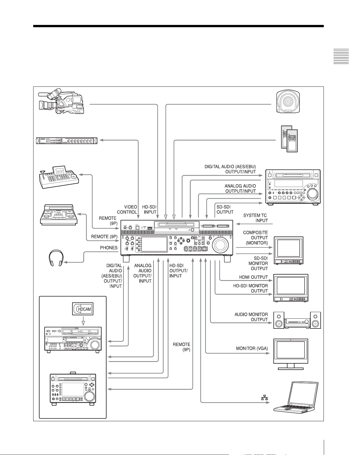
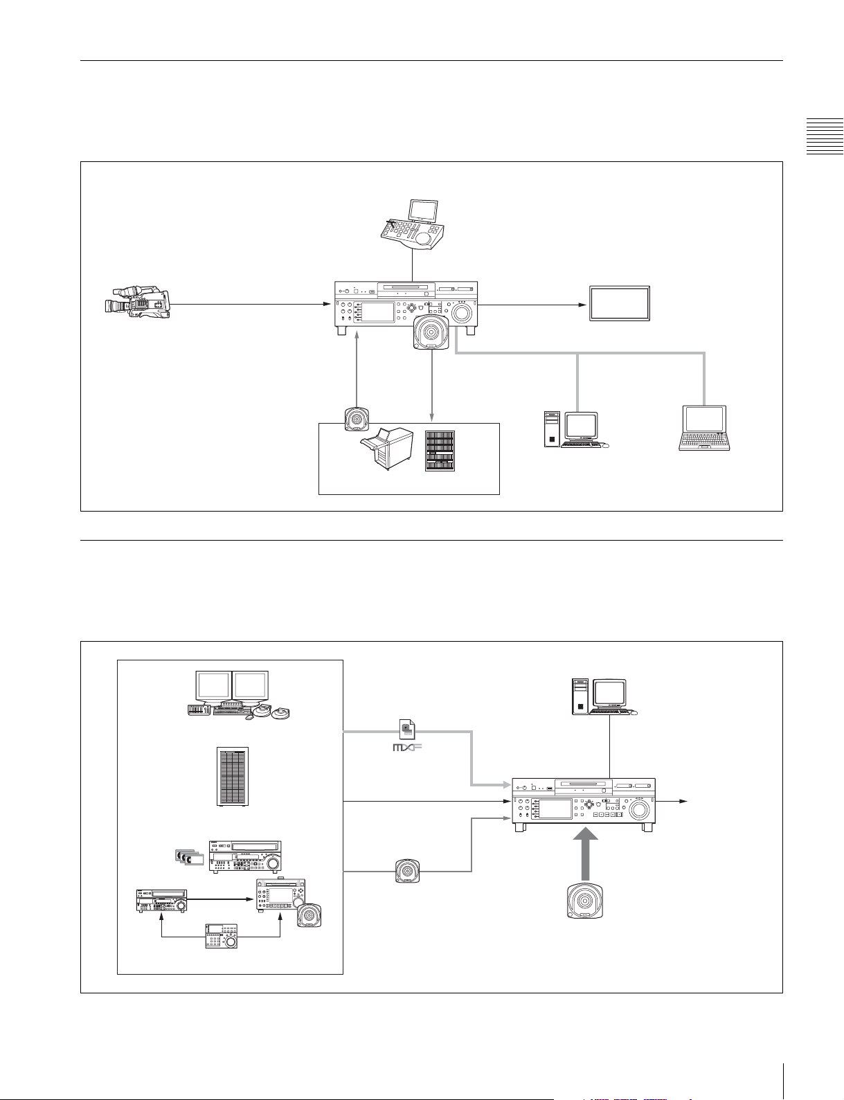
System Configurations
The figure below shows devices and media that can be
used with this unit.
You can use this unit and these devices to configure the
following systems.
PDW-700/PMW-500
HKDV-900 Video Control Unit
VDCP controller
• Satellite news gathering (SNG) system (see page 12)
• Ingesting/editing system (see page 12)
• Live production system (see page 13)
• Broadcast delivery system (see page 13)
Professional Disc
SxS memory cards
• SxS PRO
•SxS-1
PDW-1500
Chapter 1 Overview
BVE-700
Headphones
HDW-2000 series
Standard reference
timecode
SD video monitor
HD video monitor
Audio monitor
PC monitor
PDW-F1600/HD1500
Laptop computer
System Configurations
11
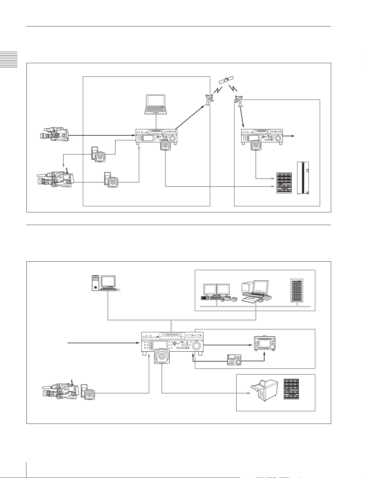
Satellite news gathering (SNG) system
The following figure shows an example of SNG system in
which this unit is used as both server and backup recorder.
Chapter 1 Overview
Camcorder
Camcorder
On the satellite truck
Reuse media
Save to internal storage
Ingesting/editing system
SDI signal
This unit
Computer
DVB-ASI
TS signal
Save clips
(installed with XDCAM Browser)
DVB-ASI
TS signal
This unit
Playout
Save clips
Archive system
The following figure shows an example of system in which
this unit is used as both editing feeder and backup recorder.
Computer (ingestion controller)
Remote control (via
Line input
Camcorder
Internet Protocol/
Web Service API)
SDI/DVB-ASI TS signal
Recording data
Global Ethernet
This unit
Save clips
Nonlinear editing system
Linear editing system
SDI signal
RS422
Server
FTP/CIFS
PDW-F1600
(recorder)
Archive system
12
System Configurations
Live production system
The following figure shows an example of sports relay or
live recording system in which this unit is used as both
editing feeder and backup recorder.
Slow-motion/replay controller
Chapter 1 Overview
This unit
Live video (SID signal)
Camcorder
Read in video
from library
Save
recorded clips
Archive/library system
Delivery system
The following figure shows an example of program
delivery system in which this unit is used as both server
and backup player.
RS422 (VDCP)
FTP/CIFS
SDI signal
Global Ethernet
Nonlinear editing
system (pre-/postediting)
Monitor
Slow-motion/
replay video
Computer (XDCAM
Browser installed)
Nonlinear editing system
Material server
Recording system
MXF file
SDI signal
Save clips
Global Ethernet
This unit
Play out emergency video directly
from Professional Disc
Computer (program
transmission controller)
RS422 (VDCP)
Playout
System Configurations
13
Names and Functions of
Parts
Chapter 2 Names and Functions of Parts
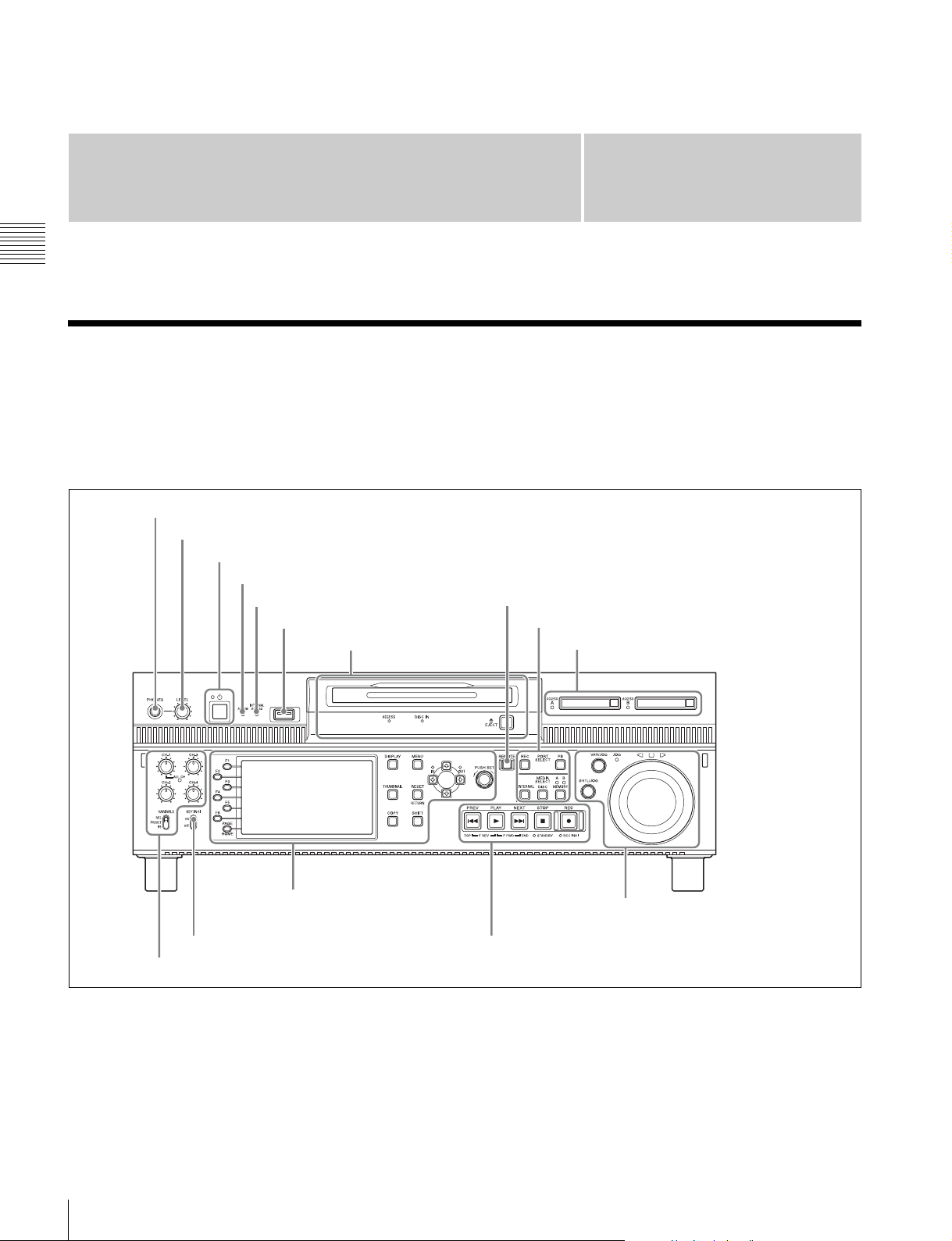
Front Panel
The names and symbols of buttons and knobs on the front
panel are color coded according to function.
White: Function when the button or knob is operated
independently.
1 PHONES jack
2 LEVEL adjustment knob
3 On/standby (1) button and indicator
4 ALARM indicator
5 INTERNAL ACCESS indicator
6 MAINTENANCE connector
2 Disc control section
(see page 16)
Chapter
Orange: Function when the button is operated with the
SHIFT button held down.
Blue: Function related to thumbnail operations.
7 REMOTE button
1 Port and media selection section (see page 15)
3 Memory card slots (see page 16)
2
5 Display/menu control
section (see page 17)
8 KEY INHI switch
4 Audio level adjustment section (see page 16)
a PHONES jack
This is a standard stereo jack. Connect stereo headphones
to monitor the audio during recording and playback. (Nonaudio signals are muted.) The monitored channel is
selected with MONITR L and MONITR R on the HOME
page of the function menu (see page 41).
14
Front Panel
7 Shuttle/jog/variable-speed playback
control section (see page 19)
6 Recording and playback control section (see page 18)
b LEVEL (volume) adjustment knob
Adjust the volume of headphones with this knob. You can
also cause this knob to simultaneously adjust the output
volume from the AUDIO MONITOR OUTPUT R, L
connectors on the rear panel. To do this, set setup menu
item 114 AUDIO MONITOR OUTPUT LEVEL to
“variable”.
c On/standby (1) button and indicator
When the main power switch on the rear panel is in the on
position, this switches the unit between the operating state
(the indicator is lit green) and the standby state (the
indicator is lit red).
To put the unit into the operating state, press this button
and hold it down for a short time (0.25 seconds or longer)
while the indicator is lit red. The indicator changes to lit
green, and the unit enters the operating state.
To put the unit into the standby state, press this button and
hold it down for a longer time (1 second or longer) while
the indicator is lit green. The indicator changes to flashing
green and then lit red, and the unit enters the standby state.
When using this unit, normally leave the main power
switch on the rear panel in the on position, and use this
button to switch the unit between the operating state and
standby state.
Note
To switch the state of this unit from standby state (the main
switch on the rear panel is on) to operative state, wait at
least three seconds after the unit has entered standby state
and then press the on/standby button on the front panel.
d ALARM indicator
This flashes to alert you to an error in the unit, and goes out
when the cause of the error is removed.
Flashing red: An error that requires service has occurred,
in most cases a hardware error.
Flashing orange: A warning level error has occurred.
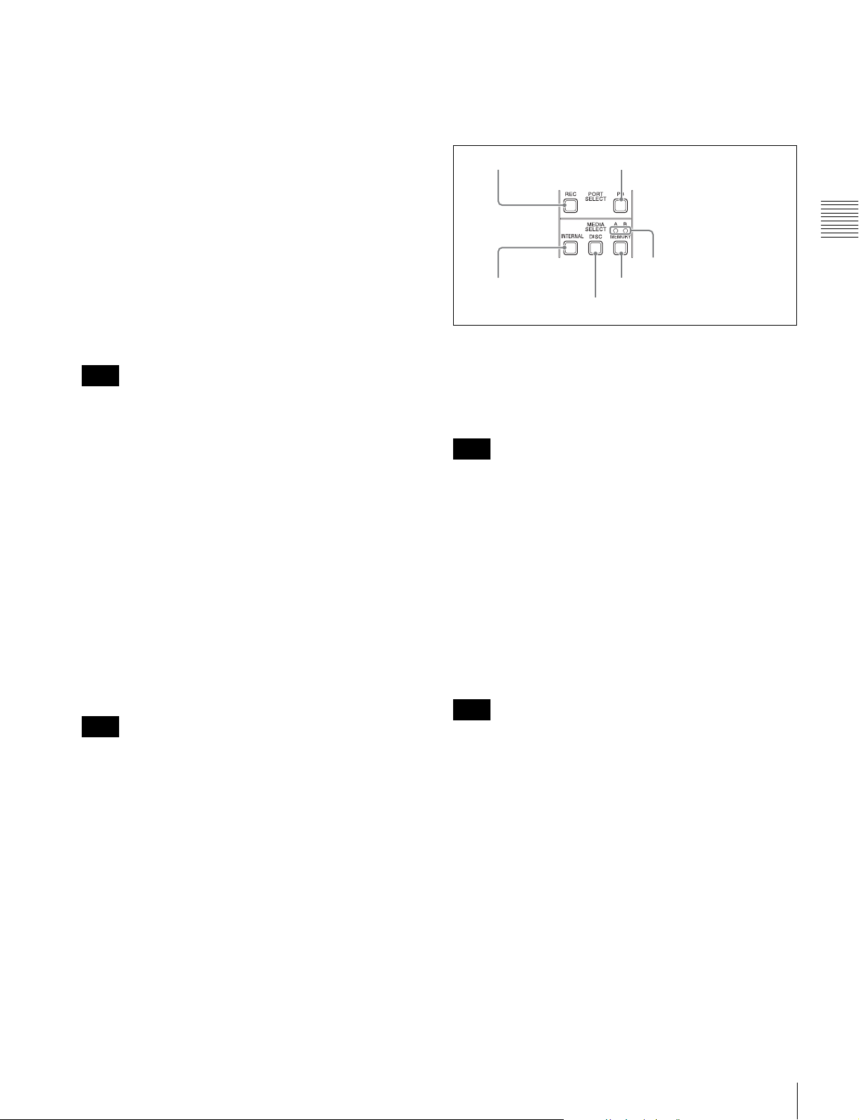
1 Port and media selection section
This unit has a recording port and a playback port. You can
control these ports independently by selecting one of them
with the REC PORT or PB PORT button.
1 REC PORT button
3 INTERNAL
button
a REC PORT (recording port) button
Before performing recording operations on the front panel
of this unit, press this button to select the recording port.
E-E signals (the video of the input signals) are output to the
display and to the video monitor output connectors.
Note
When a clip list screen is displayed, pressing this button
does not output E-E signals to the display. To operate this
button, first press the THUMBNAIL button to switch to
the basic operation screen or the video monitor screen.
Even when a clip list screen is displayed, pressing this
button switches the output signals of the video monitor
output connectors to E-E signals.
2 PB PORT button
6 Slot selection lamps
5 MEMORY button
4 DISC button
Chapter 2 Names and Functions of Parts
A message appears on the display when this indicator
starts flashing. For details, see “Troubleshooting”
(page 101).
e INTERNAL (internal storage) ACCESS indicator
This lights when the internal storage is accessed.
Note
Do not turn off the main power switch on the rear panel or
disconnect the power cord while the INTERNAL
ACCESS indicator is lit. Doing so may corrupt the data on
the storage.
f MAINTENANCE connector
This is the USB connector for maintenance.
g REMOTE button
Press this button, turning it on, to perform remote control
of this unit from a device connected to the REMOTE (9P)
1 and 2 connectors.
This allows you to control the recording and playback
ports individually.
h KEY INHI (inhibit) switch
This turns key operation inhibit mode on or off.
b PB PORT (playback port) button
Before performing playback operations on the front panel
of this unit, press this button to select the playback port.
Playback video is output to the display and to the video
output connectors/video monitor connectors.
Note
When a clip list screen is displayed, pressing this button
does not output playback signals to the display or video
output connectors. To operate this button, first press the
THUMBNAIL button to switch to the basic operation
screen or the video monitor screen.
Even when a clip list screen is displayed, pressing this
button switches the output signals of the video monitor
output connectors to playback video signals.
c INTERNAL (internal storage) button
This button selects internal storage as the operation target
media.
d DISC button
This button selects a Professional Disc as the operation
target media.
Front Panel
15
e MEMORY button
This button selects an SxS memory card as the operation
target media.
a Memory card slots
These two slots (A and B) can receive SxS memory cards
(see page 46).
f Slot selection lamps
These light to indicate the selected memory card slot.
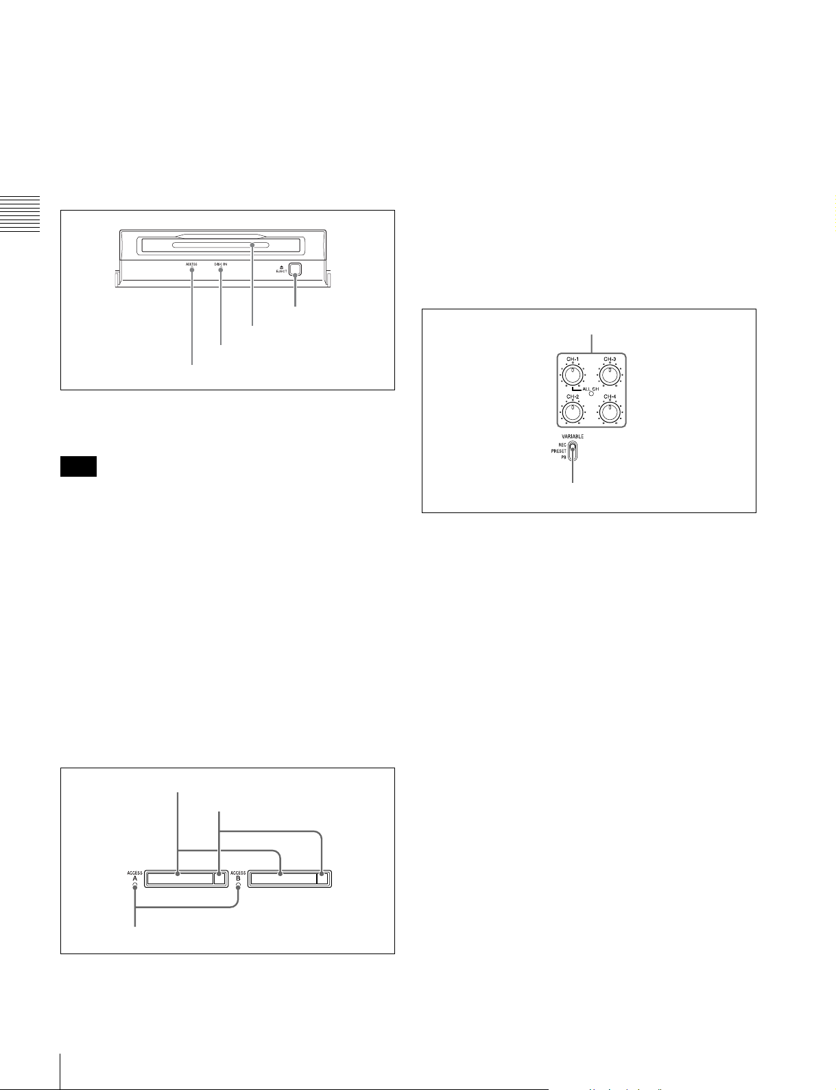
2 Disc control section
Chapter 2 Names and Functions of Parts
4 EJECT button
3 Disc slot
2 DISC IN indicator
1 DISC ACCESS indicator
a DISC ACCESS indicator
This lights when the Professional Disc is accessed.
Note
While the ACCESS indicator is lit, do not turn off the main
power switch on the rear panel or disconnect the power
cord.
This could lead to a loss of data from the disc.
b DISC IN indicator
This lights when a Professional Disc is inserted.
c Disc slot
Insert a Professional Disc in this slot (see page 44).
d EJECT button
To remove the Professional Disc, press this button (see
page 44).
3 Memory card slots
b Eject buttons
To remove the SxS memory card from the slot, press the
eject button to release the lock, then press the button once
more. This makes the media come out of the slot partially
(see page 47).
c MEMORY ACCESS A/B lamps
Indicate the state of slots A and B (see page 47).
4 Audio level adjustment section
1 CH-1/ALL CH, CH-2 to CH-4 adjustment knobs
2 VARIABLE switch
a CH-1/ALL CH, CH-2 to CH-4 (audio level)
adjustment knobs
Depending on the setting of the VARIABLE switch, these
adjust the input audio or playback audio levels of channels
1 to 4.
You can adjust levels of channels 5 to 8 using the function
menu. For details, see “P3 AUDIO page” (page 43).
By the setting of setup menu item 131 AUDIO VOLUME,
you can enable the CH-1/ALL CH adjustment knob to
simultaneously adjust all eight channels. When this
simultaneous adjustment is enabled, the ALL CH indicator
lights.
16
Front Panel
1 Memory card slots
2 Eject buttons
3 MEMORY ACCESS A/B lamps
b VARIABLE (audio level adjustment selector)
switch
This selects whether input audio levels or playback audio
levels are adjusted by the CH-1/ALL CH and CH-2 to CH4 adjustment knobs for channels 1 to 4, or by the function
menu setting for channels 5 to 8.
REC: Adjust the input audio levels. The playback audio
levels are fixed at their preset values.
PRESET: The audio levels are fixed at their preset values.
PB: Adjust the playback audio levels. The input audio
levels are fixed at their preset values.
Note
It is not possible to adjust the audio levels of the recording
and playback ports simultaneously.
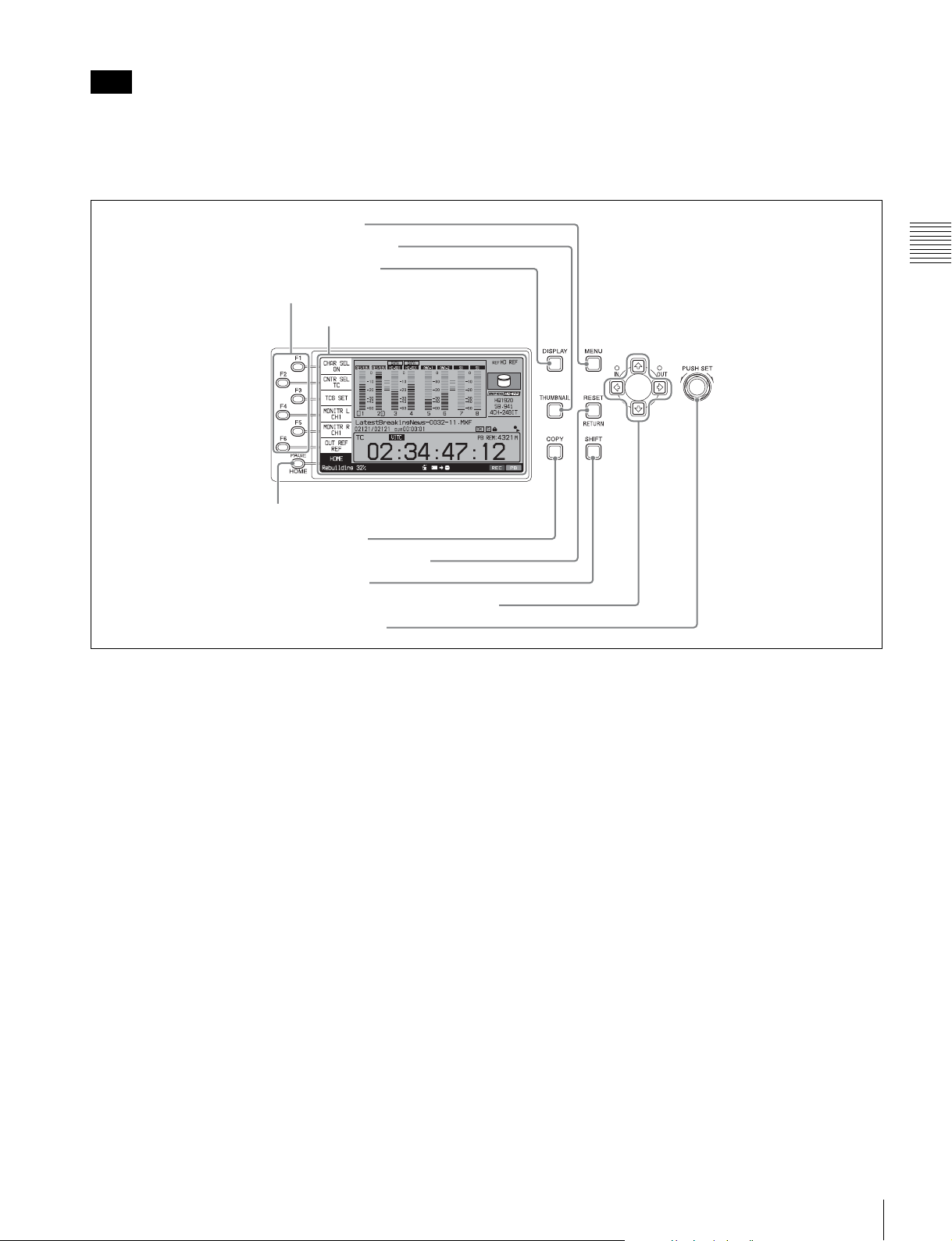
5 Display/menu control section
5 MENU button
4 THUMBNAIL button
3 DISPLAY button
1 Function buttons (F1 to F6)
2 Display
6 PAGE/HOME button
To set the audio level of each port separately, adjust one or
the other by using external audio equipment connected to
a REMOTE (9P) connector (1 or 2).
Chapter 2 Names and Functions of Parts
7 COPY button
8 RESET/RETURN button
9 SHIFT button
q; Arrow buttons and IN/OUT indicators
qa PUSH SET knob
a Function buttons (F1 to F6)
These buttons are enabled when the function menu (see
page 41) is visible. Each press of a button changes the
setting of the corresponding item in the menu.
When the setup menu (see page 77) is displayed, these
buttons function as menu control buttons.
For convenience, this manual refers to these buttons as
buttons F1 to F6, in order from the top.
b Display
Displays video being recorded, E-E video, playback video,
menus, audio level meters, and data such as timecode or
clip information. It can be switched between a basic
operation screen (see page 20), a video monitor screen (see
page 23), and a clip list screen (see page 59).
For details, see page 58.
c DISPLAY button
Each press of this button switches between the basic
operation screen, the video monitor screen, and the clip list
screen (see page 58).
When the clip list screen is displayed, this button switches
the display between thumbnails view and details view.
d THUMBNAIL button
When this button is pressed when the basic operation
screen or video monitor screen is displayed, a list of clips
saved on the currently selected media is displayed. (That
is, the current screen is switched to a clip list screen.)
When pressed again, returns to the basic operation screen
or the video monitor screen.
e MENU button
Starts the setup menu, and starts the Clip Menu from a clip
list screen (see page 61). The same information is also
superimposed on the display on a video monitor connected
to the unit. When pressed again, the setup menu or the Clip
Menu disappears.
f PAGE/HOME button
When pressed alone, functions as the PAGE button. When
pressed together with the SHIFT button, functions as the
HOME button.
PAGE button: Displays the function menu, if it is not
visible. (The most recently displayed page of the
function menu appears.)
HOME button: When pressed with the function menu
visible, returns to the HOME page of the function
menu.
Front Panel
17
g COPY button
Displays the Clip Copy screen. (see page 55).
b PLAY button
To start playback, press this button, turning it on.
h RESET/RETURN button
Functions as the RESET button or the RETURN button.
RESET button: Resets counters or the setting values of
the timecode generator.
RETURN button: In clip list screens, returns to the
previous procedure.
i SHIFT button
Chapter 2 Names and Functions of Parts
Switches between functions for any button with two
functions.
j Arrow buttons and IN/OUT indicators
The arrow buttons are used for clip selection, menu setting
operations, and so on.
When you use the arrow buttons to set an IN and OUT
point in the clip, it becomes possible to copy only the part
defined by the IN and OUT points (see page 56). When an
IN and OUT points are set in the clip, the IN and OUT
indicators light.
k PUSH SET knob
This is used for menu operations and thumbnail operations
in a clip list screen. Turn the knob to select items, and press
it to confirm the selection. This button is also used to set
numerical and timecode values.
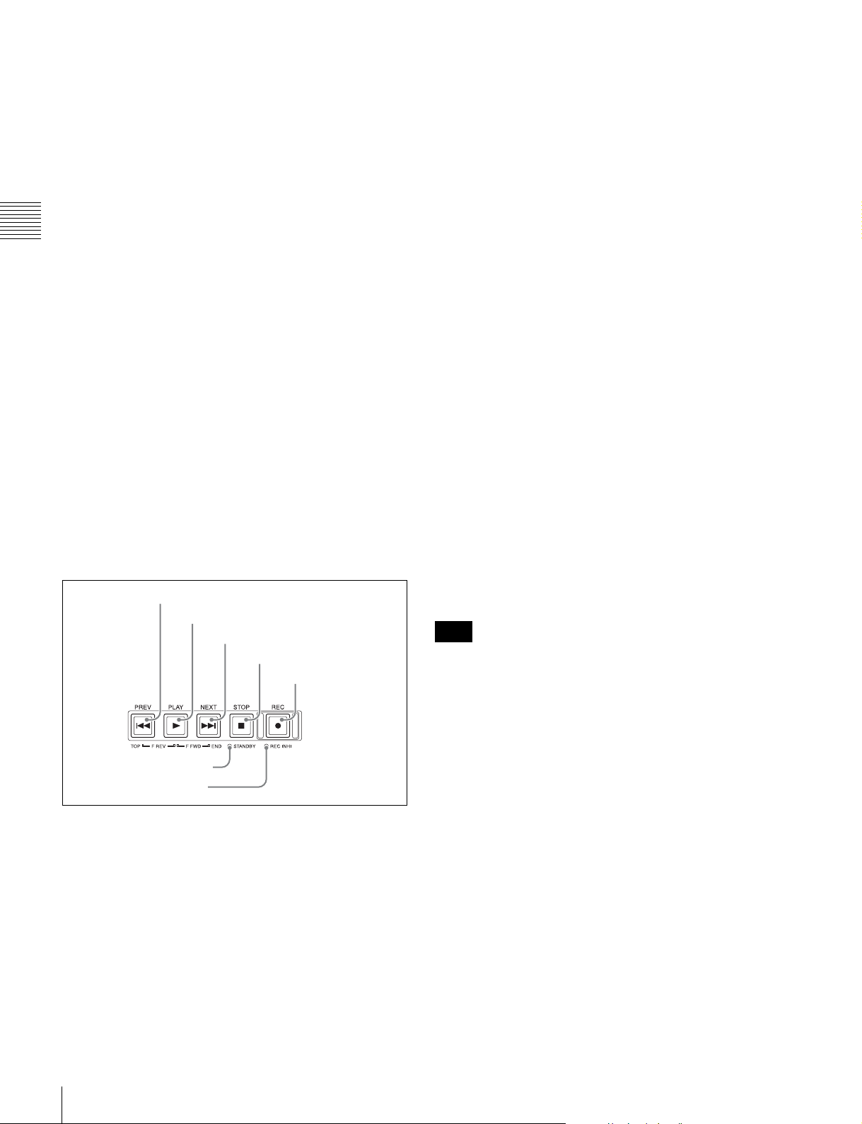
6 Recording and playback control section
1 PREV button
2 PLAY button
3 NEXT button
4 STOP button
5 REC button
7 STANDBY indicator
6 REC INHI indicator
a PREV (previous) button
Press this button, turning it on, to show the first frame of
the current clip. While the first frame of a clip is shown,
pressing this button jumps to the beginning of the previous
clip. This button is also used together with other buttons
for the following operations.
Reverse direction high-speed search: Hold down the
PLAY button, and press this button. A high-speed (50
times normal) search in the reverse direction is carried
out.
Displaying the first frame of the first clip: Hold down
the SHIFT button, and press this button.
c NEXT button
Press this button, turning it on, to jump to the next clip and
show the first frame. During chase play, play jumps to the
last frame that is playable at that time.
This button is also used together with other buttons for the
following operations.
Forward direction high-speed search: Hold down the
PLAY button, and press this button. A high-speed (50
times normal) search in the forward direction is
carried out.
Displaying the last frame of the last clip: Hold down the
SHIFT button, and press this button.
d STOP button
To stop recording or playback, press this button, turning it
on. The frame at the stop point appears.
e REC (record) button
To start recording, hold down this button, and press the
PLAY button. The recording takes place on an unrecorded
part of the media.
To stop recording, press the STOP button.
f REC INHI (recording inhibit) indicator
Lights when Professional Disc is selected as the operation
target media and a disc in record-inhibited state is loaded
(see page 44).
Also lights when an SxS memory card is loaded and
selected as the operation target media.
Note
Recording to SxS memory cards is not possible.
g STANDBY indicator
Lights when the unit is put into disc stop mode. After a
certain time passes in a disc stop mode, the unit
automatically enters standby off mode and the indicator
goes off.
You can specify the time until the unit enters standby off
mode.
For details, see the description of setup menu item 501
STILL TIMER (see page 80).
18
Front Panel
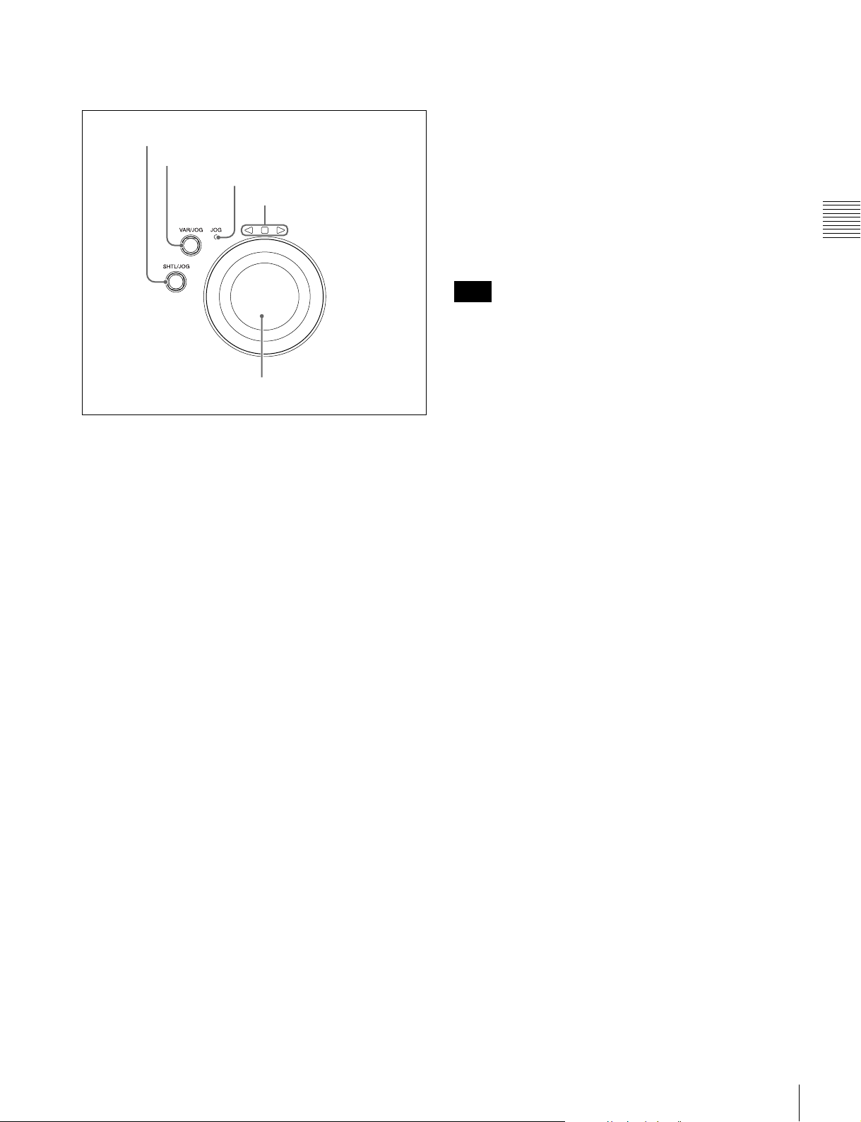
7 Shuttle/jog/variable-speed playback
control section
1 SHTL/JOG button
2 VAR/JOG button
3 JOG indicator
4 Jog/shuttle direction
indicators
5 Shuttle/jog dial
a SHTL/JOG button
Press this button, turning it on, to perform shuttle or jog
playback with the shuttle/jog dial.
• In variable-speed mode, you can make fine adjustments
to the playback speed over the range from –2 to +2 times
normal speed, according to the angular position of the
dial. There is a detent at the center position, for still
image playback.
Regardless of the playback mode, you will normally press
the SHTL/JOG or VAR/JOG button before turning the
dial. But it is also possible to put the unit into shuttle, jog,
or variable-speed mode simply by turning the dial (by
setting setup menu item 101 SELECTION FOR SEARCH
DIAL ENABLE to “dial”).
Note
If you do set the above item to “dial”, then you should
return the shuttle/jog dial to the center position after
conducting shuttle or variable-speed playback. If you do
not return the dial to the center position, playback in
shuttle or variable-speed mode can start because of
vibrations during other operations.
Chapter 2 Names and Functions of Parts
b VAR/JOG button
Press this button, turning it on, to perform variable-speed
or jog playback with the shuttle/jog dial.
c JOG indicator
Lights in green when the shuttle/jog dial is in jog mode.
d Jog/shuttle direction indicators
These show the playback direction in jog, shuttle, or
variable-speed mode.
b (green): Lights during playback in the reverse direction.
B (green): Lights during playback in the forward
direction.
x (red): Lights during still image display.
e Shuttle/jog dial
The dial switches between shuttle/variable-speed mode
and jog mode each time that you press it all the way in.
Shuttle/variable-speed mode: The dial is in the raised
position.
Jog mode: The dial is in the depressed position (the JOG
indicator is lit).
Turn the dial to the right to play in the forward direction,
and turn it to the left to play in the reverse direction.
• In jog mode, the playback speed varies from –1 to +1
times normal speed, according to the rotation speed of
the dial. There are no detents.
• In shuttle mode, the playback speed varies in the range
±20 times normal speed, according to the angular
position of the dial. There is a detent at the center
position, for still image playback.
Front Panel
19

Display screen
Basic operation screen
Chapter 2 Names and Functions of Parts
1 Function menu
2 Audio input display/audio level meters
3 System information
4 Media status display
5 Recording or playback format
6 Clip information
7 Recording or chase play display
8 Time data display area
9 Status display area
a Function menu
Use the PAGE/HOME button to display this menu, and to
switch between the pages (HOME, P1 to P5) of the menu.
Each page has one to six setting items. Press the
corresponding function button to change a setting.
For details, see “Basic Operations of the Function Menu”
(page 41).
b Audio input display/audio level meters
Displays information about audio.
A Input signal display
B Data indication
F Level bars
E Reference level
D Audio channel
C Monitor channel
A Input signal display: Displays the audio input signal.
.
Display Input signal
ANA-1 Analog audio signal Channel 1, 3, 5, 7
ANA-2 Channel 2, 4, 6, 8
AES/EBU AES/EBU format digital audio signal (flashes
when there is no input signal)
HD-SDI HD-SDI audio signal (flashes when there is
no input signal)
SD-SDI SD-SDI audio signal (flashes when there is
no input signal)
SG Test signal from the internal signal generator
DVB-ASI DVB-ASI TS signal (flashes when there is no
input signal)
When the video input signal is set to “DVB-
ASI”, A1 INPUT to A8 INPUT are
automatically set to “DVB-ASI”.
B Data indication: Appears when the input signals are
non-audio signals.
C Monitor channel: Displays the audio monitoring
channels set with MONITR L and MONITR R on the
HOME page of the function menu (see page 41).
D Audio channel: Displays the audio channels.
Also indicates preset or variable-speed mode by its
color (see page 16).
White: Preset mode
Green: Variable-speed mode
E Reference level: Displays the reference level for
recording as set in the maintenance menu.
F Level bars: Display the audio recording or playback
levels of channels 1 to 8. The OVER indicators light
when the audio level exceeds 0 dB.
20
Front Panel
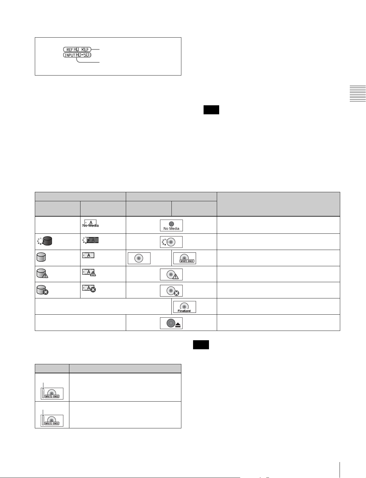
c System information
A Reference signal
SD-SDI: SD-SDI video input
SG: Test video signal from the internal signal
generator
DVB-ASI
1)
: DVB-ASI TS signal
B Video input display
A Reference signal: This displays the type of reference
signal to which this unit is synchronizing.
When there is no display, the unit is synchronizing to
1) When the maintenance menu item M22: OPTION SETTING >DVBASI is set to “ON” with the optional PDBK-202 being installed (see
page 92).
The video signal input is selected with V INPUT on
page P1 INPUT of the function menu (see page 42).
the internal reference signal.
INPUT: Input video
HD REF: HD-format reference signal
SD REF: SD-format reference signal
B Video input display: This displays the currently
Note
The display blinks when there is no video input signal,
and when the video input signal does not match the
system frequency of this unit.
selected video input signal.
HD-SDI: HD-SDI video input
d Media status display
Displays the icons in the following table to indicate the
status of the selected recording media.
Icons Professional Disc Status
Internal storage Memory card
(slot A selected)
— Not loaded
PFD23A/
PFD50DLA
PFD128QLW
Chapter 2 Names and Functions of Parts
— Finalized
— Being ejected
The PFD128QLW media status display changes with the
remaining capacity of the recordable resource space (for
writing the disc management data, etc.).
Icon Status
Yellow bar
Red bar
The available recordable resource space is
running out.
There is no available recordable resource
space on the disc.
Note
The remaining capacity of recordable resource space is not
the same as the remaining recording capacity. When there
is no available recording resource space is left on the disc,
file writing may be disabled even with sufficient available
storage remaining.
e Recording or playback format
When the recording port is selected, displays the recording
format. When the playback port is selected, displays the
Being mounted
Normal status
Warning level error has occurred (finalizing is
impossible)
Error has occurred (restoring is impossible)
format of the clip being played.
Front Panel
21
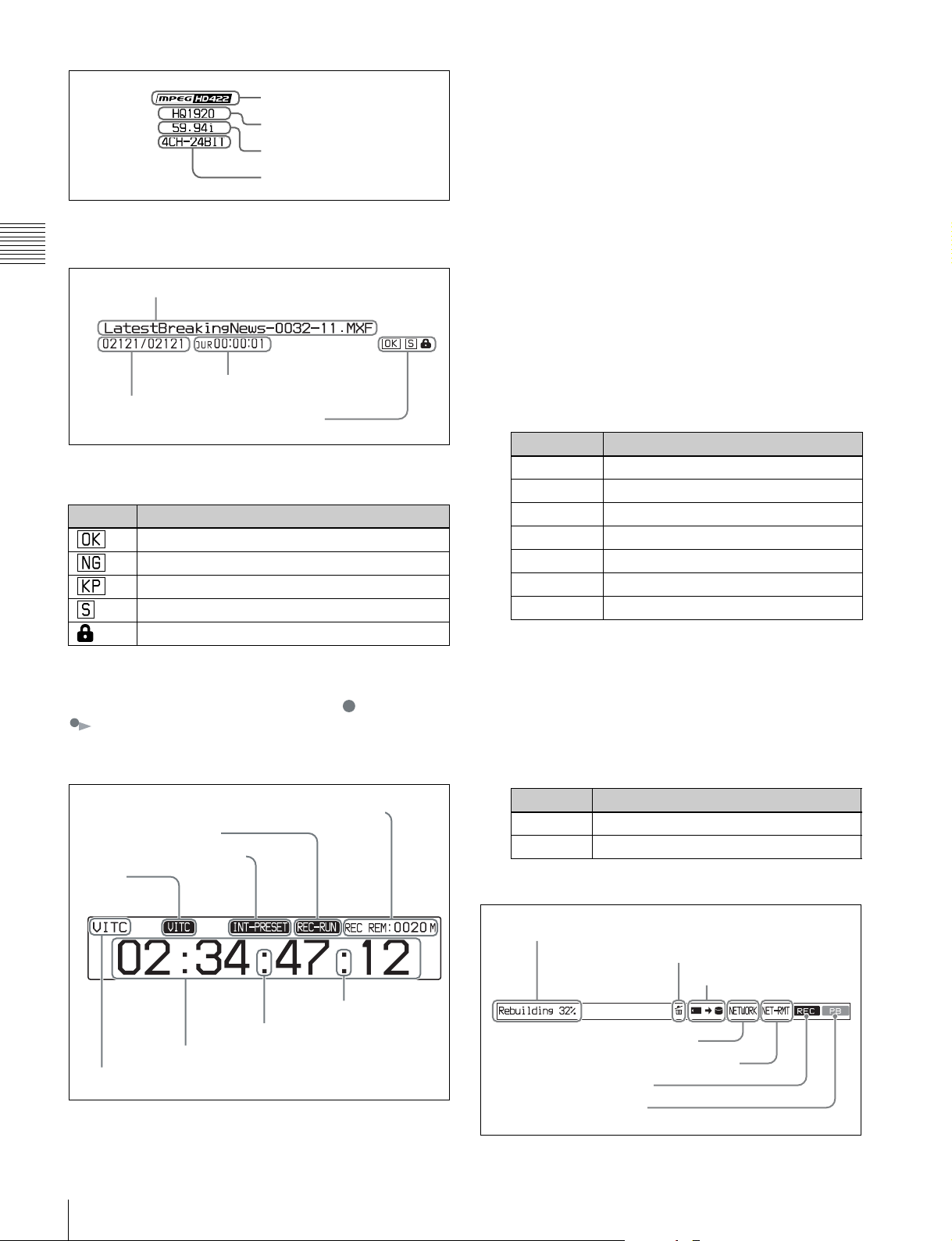
Codec
Video format
System frequency
Audio format
f Clip information
Displays clip information.
Chapter 2 Names and Functions of Parts
Clip name
Duration
Clip number/total number of clips
Property icons
During playback, the icons in the following table appear to
indicate the properties that have been set in a clip.
Icon Description
An OK flag is set
An NG flag is set
A KEEP flag is set
A shot mark is set
The clip is locked (protected)
g Recording or chase play display
When the recording media is the internal storage, an icon
appears to indicate the status of the unit ( : recording,
: chase play).
h Time data display area
A Remaining media capacity for recording or
playback: Displays the amount of remaining capacity
for recording or playback on the media.
B REC RUN/FREE RUN: Displays the timecode run
mode. The run mode is set with RUN MODE on page
P4 TC of the function menu (see page 43).
C Timecode generator mode: Displays the timecode
source and generation method (preset or regenerate).
These are set with TCG and PRST/RGN on page P4
TC of the function menu (see page 43).
D VITC: Lights in the following cases.
• When VITC is read in playback mode. (This has no
relations to the display in the time data display
area.)
• When VITC recording is possible.
E Time data type: Displays the type of time data
displayed in the time data display area. The type of
time data is selected with CNTR SEL on the HOME
page of the function menu (see page 41).
Display Type of time data
TC Timecode
COUNTER Elapsed recording/playback time
UB User bits
VITC VITC
VIUB VIUB
TCG Timecode generator value
UBG User bits generator value
F Time data: Normally displays timecode or VITC,
according to the selection made with TCR on page P4
TC of the function menu.
G DF/NDF indication: Displays the frame count mode
for the internal timecode reader (TCR) and internal
timecode generator (TCG). The frame count mode is
set with DF/NDF on page P4 TC of the function menu
(see page 43).
A Remaining media capacity for recording or playback
B REC RUN/FREE RUN
C Timecode generator mode
D VITC
G DF/NDF
indication
(TCR)
22
F Time data
E Time data type
Front Panel
G DF/NDF
indication
(TCG)
Display Frame count mode
. DF (drop-frame mode)
: NDF (non-drop-frame mode)
i Status display area
A Error, warning, and alarm messages
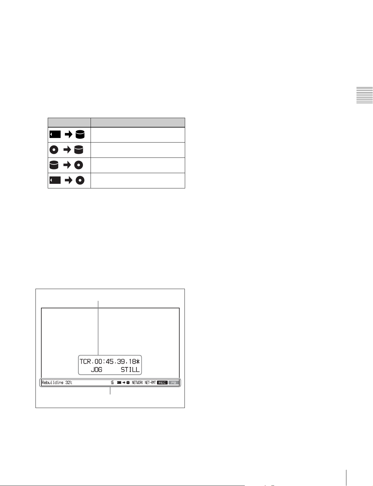
B Delete icon
C Copy icon
D Network connection display
E Network remote connection display
F Recording display
G Playback display
A Error, warning, and alarm messages: Messages
about operations and the status of the unit appear here.
The seriousness of the message is indicated by the
color, as follows.
Red: Error message (flashing)
Orange: Warning message
White: Alarm message
B Delete icon: Flashes while a clip deletion is being
executed.
C Copy icon: An icon representing the copy source and
copy destination light while a copy operation is being
executed between media.
Icon Description
Copy from memory card to internal
storage
Copy from Professional Disc to
internal storage
Copy from internal storage to
Professional Disc
Copy from memory card to
Professional Disc
D Network connection display: Lights while data is
being exchanged with a network connected external
device.
E Network remote connection display: Lights during a
network remote control connection to an external
device.
F Recording display: Lights when recording to the
internal storage is being performed.
G Playback display: Lights when a clip on the internal
storage or disc is in the open state.
Chapter 2 Names and Functions of Parts
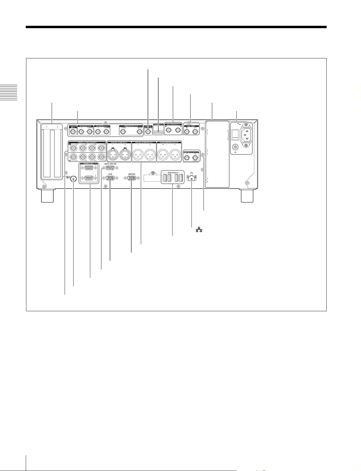
Video monitor screen
A Superimposed information
B Status display area
A Superimposed information: Appears when CHAR
SEL on the HOME page of the function menu is set to
“ON”.
B Status display area: Displays messages and icons
about the status of the unit (see page 22).
Front Panel
23
Rear Panel
Chapter 2 Names and Functions of Parts
1 PCIe expansion slot
1 HD/SD-SDI signal input/output
section (see page 25)
2 DVB-ASI OUTPUT connector
3 HDMI OUTPUT connector
4 REF. VIDEO INPUT connectors
2 Timecode input/output section (see page 26)
5 Redundant power supply unit installation section
3 Power supply section
(see page 26)
5 Analog audio signal input/output section (see page 27)
q; MONITOR connector
9 GPIO connector
8 VIDEO CONTROL connector
7 REMOTE (9P) 1, 2 connectors
6 SYSTEM TC INPUT connector
4 Digital audio signal input/output section (see page 27)
a PCIe expansion slot
For future expansion, this is provided to enable the
connection of units having a PCI Express interface.
b DVB-ASI OUTPUT (DVB-ASI output) connector
(BNC type)
This connector can output DVB-ASI TS signals when the
optional PDBK-202 MPEG TS Board is installed. For this,
it is necessary to set the maintenance menu item M22:
OPTION SETTING >DVB-ASI to “ON” (see page 92).
For details, see “About DVB-ASI Input/Output (When the
Optional PDBK-202 Is Used)” (page 111) for more
information about DVB-ASI TS signals.
qd COMPOSITE OUTPUT 1, 2 (MONITOR) connectors
qs (network) connector
qa MAINTENANCE connectors
c HDMI OUTPUT connector
Outputs digital signals (video, audio, control signals).
Output signals are E-E signals or playback signals,
according to the setting of the REC PORT and PB PORT
buttons on the front panel.
Allows you to connect a device with an HDMI input
connector, such as an HD projector or a high-definition
TV.
Audio output signals are the signals of the channels
selected with MONITR L and MONITR R on the HOME
page of the function menu.
d REF. VIDEO INPUT (reference video signal input)
connectors (BNC type)
The two connectors form a loop-through connection; when
a reference video signal is input to the left connector (IN),
24
Rear Panel
the same signal is input from the right connector ( ) to
a connected device. When no connection is made to the
right connector, the left connector is automatically
terminated with an impedance of 75 ohms.
e Redundant power supply unit installation section
When using this unit in a system that requires high
reliability, you can back up the unit’s power supply by
installing the optional XDBK-101 Optional Power Supply.
This allows operation to continue even if one of the power
supply units fails.
To enable continuous operation after failure, set
maintenance menu item M22: OPTION SETTING
>REDUNDANT PSU to “ON”.
Note
The power supply and XDBK-101 do not support hot
swapping. Always turn the main power switch off before
exchanging the power supply or adding the XDBK-101.
f SYSTEM TC INPUT (system timecode input)
connector
If you want to input the standard reference timecode signal
of a broadcasting station as time data information, use this
connector to input it.
l (network) connector (RJ-45 type)
This is a 10BASE-T/100BASE-TX/1000BASE-T
connector for network connection.
CAUTION
• For safety, do not connect the connector for peripheral
device wiring that might have excessive voltage to this
port. Follow the instructions for this port.
• When you connect the network cable of the unit to
peripheral device, use a shielded-type cable to prevent
malfunction due to radiation noise.
m COMPOSITE OUTPUT (analog composite video
output) 1, 2 (MONITOR) connectors (BNC type)
Output analog composite video signals. Output signals of
the 2 (MONITOR) connector are E-E signals or playback
signals, according to the setting of the REC PORT and PB
PORT buttons on the front panel. You can superimpose
timecodes or error messages on the output of the 2
(MONITOR) connector when CHAR SEL on the HOME
page of the function menu is set to “ON”.
See “Basic Operations of the Function Menu” on page 41
for more information about the CHAR SEL setting.
Chapter 2 Names and Functions of Parts
g REMOTE (9P) (remote control 9-pin) 1, 2
connectors (D-sub 9-pin)
REMOTE (9P) 1 connector: Controls the recording port.
Connect a controller that supports the VDCP
protocol.
REMOTE (9P) 2 connector: Controls the playback port.
Connect a VTR or a controller that supports the
RS-422A Sony 9-pin VTR protocol (see page 32).
h VIDEO CONTROL connector (D-sub-9-pin)
Connect an HKDV-900 video control unit.
See page 114 for correspondence between setting items of
HKDV-900 and setup menu of this unit.
i GPIO (general-purpose I/O) connector
When you are using this unit in a larger system, such as a
playout system, this connector allows you to connect an
external device to control this unit’s playback, and to
return tally and alarm signals to the external device.
j MONITOR connector
Outputs the same video that appears on the display of this
unit’s front panel as analog RGB component video signals.
This connector is intended for connection to the VGA
input connector of a PC monitor.
k MAINTENANCE connectors
These are the USB connectors for maintenance.
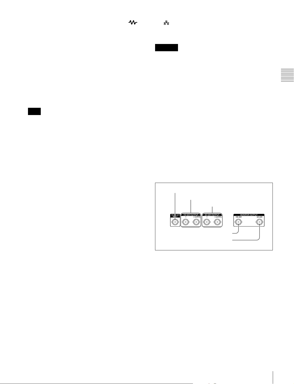
1 HD/SD-SDI signal input/output section
1 HD/SD-SDI INPUT connector
2 HD-SDI OUTPUT 1, 2 (SUPER) connectors
3 SD-SDI OUTPUT 1, 2
(SUPER) connectors
4 HD-SDI MONITOR OUTPUT connector
5 SD-SDI MONITOR OUTPUT connector
a HD/SD-SDI INPUT (HD-SDI/SD-SDI signal input)
connector (BNC type)
This inputs an HD-SDI or SD-SDI format video/audio
signal.
When the optional PDBK-202 MPEG TS Board is
installed, you can input DVB-ASI TS signals to this
connector. When inputting DVB-ASI TS signals, it is
necessary to set the maintenance menu item M22:
OPTION SETTING >DVB-ASI to “ON” (see page 92),
and set V INPUT to “DVB-ASI” on page P1 INPUT of the
function menu (see page 42).
For details, see “About DVB-ASI Input/Output (When the
Optional PDBK-202 Is Used)” (page 111) for more
information about DVB-ASI TS signals.
Rear Panel
25
b HD-SDI OUTPUT 1, 2 (SUPER) (HD-SDI signal
output 1, 2 (superimpose)) connectors (BNC type)
These output HD-SDI format video/audio playback
signals.
You can superimpose timecodes or error messages on the
output of the 2 (SUPER) connector with the setting for
CHAR SEL on the HOME page of the function menu and
with the setting for setup menu item 028 HD
CHARACTER. You can always disable to superimpose
the data independent of the setting for CHAR SEL with the
setting for setup menu item 028.
Chapter 2 Names and Functions of Parts
See “Basic Operations of the Function Menu” (page 41)
for more information about the CHAR SEL settings.
See page 76 for more information about the setup menu
item 028 HD CHARACTER.
To treat the input and output signals of these connectors as
non-audio signals, set the maintenance menu item M37:
AUDIO CONFIG >M372: NON-AUDIO INPUT
(recording) (see page 93).
c SD-SDI OUTPUT 1, 2 (SUPER) (SD-SDI signal
output 1, 2 (superimpose)) connectors (BNC type)
These output SD-SDI format video/audio playback
signals.
When the unit is shipped from the factory, audio signal
output is eight channels with no switching, and RP188
timecode output is set to on. You can change these settings
with setup menu item 828 SDI AUDIO OUTPUT
SELECT and setup menu item 920 SD-SDI H-ANC
CONTROL (see page 86).
You can superimpose timecodes or error messages on the
output of the 2 (SUPER) connector with the setting for
CHAR SEL on the HOME page of the function menu and
with the setting for setup menu item 027 SD
CHARACTER. You can always disable to superimpose
the data independent of the setting for CHAR SEL with the
setting for setup menu item 027.
e SD-SDI (SD-SDI signal) MONITOR OUTPUT
connector (BNC type)
This outputs SD-SDI format video/audio signals. Output
signals are E-E signals or playback signals, according to
the setting of the REC PORT and PB PORT buttons on the
front panel.
Allows you to connect an SD monitor with an SD-SDI
input connector.
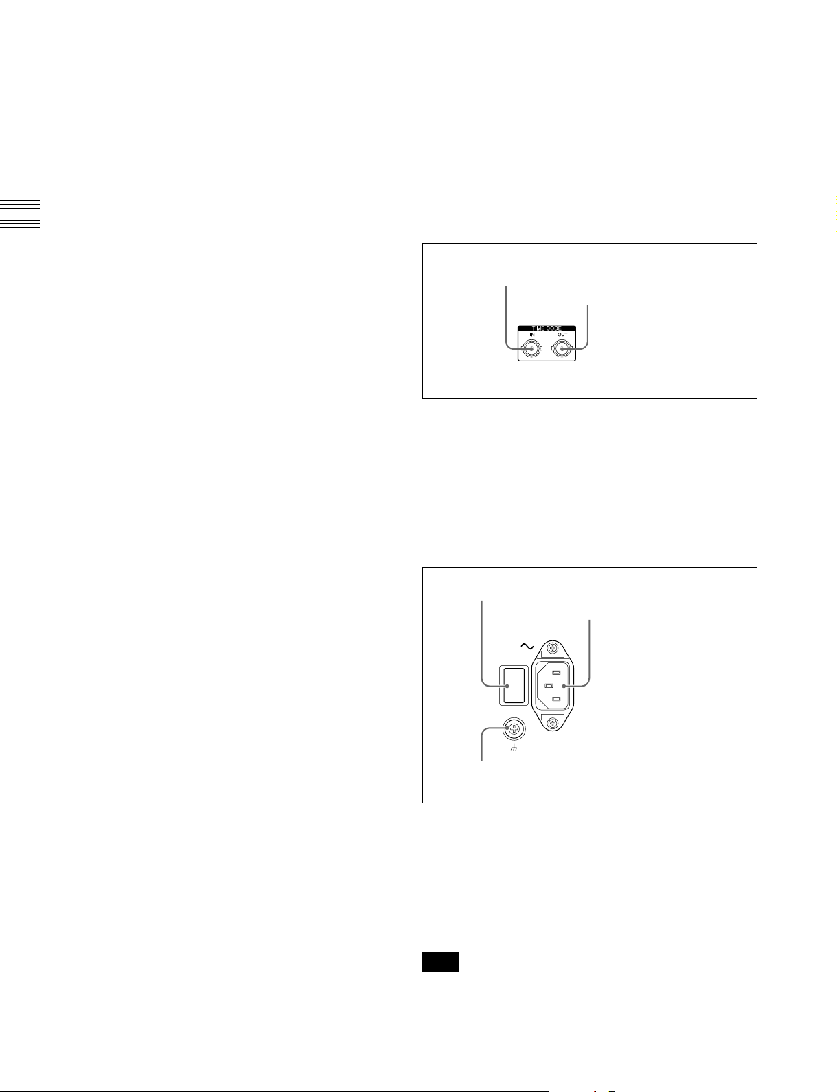
2 Timecode input/output section
1 TIME CODE IN connector
2 TIME CODE OUT
connector
a TIME CODE IN connector (BNC type)
This inputs an SMPTE timecode signal generated by an
external device.
b TIME CODE OUT connector (BNC type)
This outputs playback timecode signal.
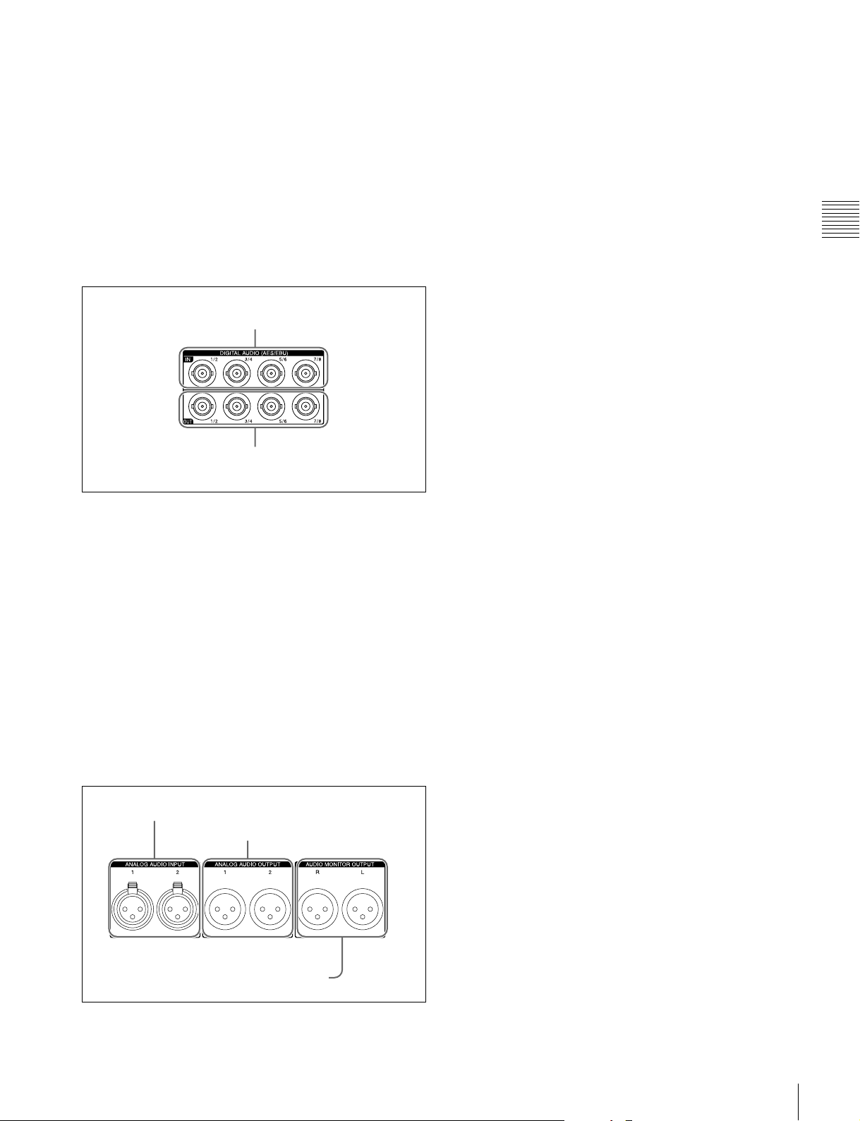
3 Power supply section
1 Main power switch
2 AC power input connector
See “Basic Operations of the Function Menu” (page 41)
for more information about the CHAR SEL settings.
See page 76 for more information about the setup menu
item 027 SD CHARACTER.
d HD-SDI (HD-SDI signal) MONITOR OUTPUT
connector (BNC type)
This outputs HD-SDI format video/audio signals. Output
signals are E-E signals or playback signals, according to
the setting of the REC PORT and PB PORT buttons on the
front panel.
Allows you to connect an HD monitor with an HD-SDI
input connector.
26
Rear Panel
3 Ground terminal
a Main power switch
Press the upper side to power the unit on. Press the lower
side to power the unit off.
When using the unit, normally leave the main power
switch in the on position, and use the on/standby button on
the front panel to switch the unit between the operating
state and standby state.
Note
Before turning the main power off, always check to be sure
that the on/standby indicator on the front panel is lit in red
(showing that this unit is in the standby state), and then
press the main power switch to the off side.
b AC power input connector (-)
Connect to an AC power supply with the power cord (not
supplied).
c Ground terminal (U)
Connect this to ground as required.
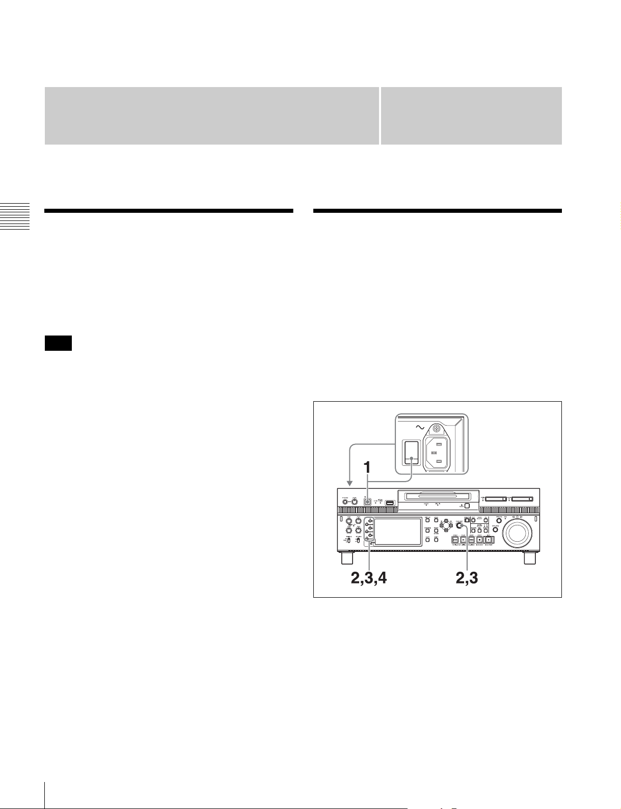
4 Digital audio signal input/output
section
1 DIGITAL AUDIO (AES/EBU) IN 1/2, 3/4, 5/6,
7/8 connectors
2 DIGITAL AUDIO (AES/EBU) OUT 1/2, 3/4, 5/6,
7/8 connectors
a ANALOG AUDIO INPUT 1, 2 connectors (XLR 3-
pin, female)
These input analog audio signals.
With A1 INPUT to A4 INPUT on page P1 INPUT (see
page 42) and A5 INPUT to A8 INPUT on page P2 INPUT
of the function menu, you can assign the signal input to
connector 1 to an odd numbered channel (1, 3, 5 or 7), and
assign the signal input to connector 2 to an even numbered
channel (2, 4, 6 or 8).
You can set the reference input level with the maintenance
menu item M37: AUDIO CONFIG (see page 93). (Factory
default setting: +4 dB)
b ANALOG AUDIO OUTPUT 1, 2 connectors (XLR
3-pin, male)
These output analog audio signals.
When the unit is shipped from the factory, the connector 1
is set to audio channel 1, and the connector 2 is set to audio
channel 2. You can change these settings with setup menu
item 824 ANALOG LINE OUTPUT SELECT (see
page 86).
You can set the output level with the maintenance menu
item M37: AUDIO CONFIG (see page 93). (Factory
default setting: +4 dB)
Non-audio signals are muted.
Chapter 2 Names and Functions of Parts
a DIGITAL AUDIO (AES/EBU) IN (digital audio
input) 1/2, 3/4, 5/6, 7/8 connectors (BNC type)
These input AES/EBU format digital audio signals.
b DIGITAL AUDIO (AES/EBU) OUT (digital audio
output) 1/2, 3/4, 5/6, 7/8 connectors (BNC type)
These output AES/EBU format digital audio signals.
To treat the input and output signals of these connectors as
non-audio signals, set the maintenance menu item M37:
AUDIO CONFIG >M372: NON-AUDIO INPUT
(recording) (see page 93).
5 Analog audio signal input/output
section
1 ANALOG AUDIO INPUT 1, 2 connectors
2 ANALOG AUDIO OUTPUT 1, 2
connectors
c AUDIO MONITOR OUTPUT R, L connectors
(XLR 3-pin, male)
Output audio signals for monitoring.
The monitored channel is selected with MONITR L and
MONITR R on the HOME page of the function menu.
Output signals are E-E signals or playback signals,
according to the setting of the REC PORT and PB PORT
buttons on the front panel.
See “Basic Operations of the Function Menu” (page 41)
for more information about the MONITR L and MONITR
R settings.
3 AUDIO MONITOR OUTPUT R, L connectors
Rear Panel
27
Preparations
Chapter 3 Preparations
Supplying Power
Chapter
Initial Setup
3
Connect the AC power input connector to an AC power
source using the specified AC power cord. To supply
power, set the main power switch on the rear panel to on,
and then press the on/standby (1) button on the front panel
and hold it down for a short time (0.25 seconds or longer).
Note
To switch the state of this unit from standby state (the main
switch on the rear panel is on) to operative state, wait at
least three seconds after the unit has entered standby state
and then press the on/standby button on the front panel.
This unit is shipped with the area of use, system frequency,
and current date and time still unset.
Therefore, you need to make initial setup settings before
using the unit. (You cannot use the unit without setting it
up.)
Once the unit has been set up, the settings are retained even
when the unit is powered off.
To set the area of use and system
frequency
28
Supplying Power / Initial Setup
1
Power the unit on.
The INITIAL SETUP screen appears on the display.
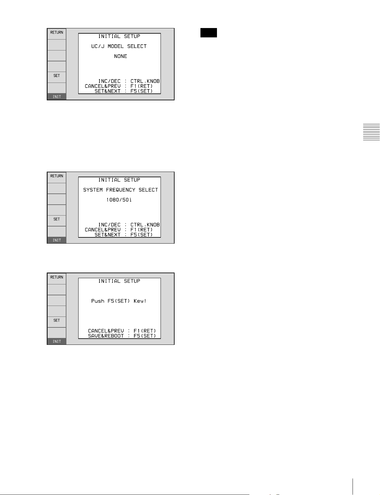
2
Turn the PUSH SET knob to select the area of use.
Display UC (for regions outside Japan) or J (for
Japan), and then press the SET function button (F5).
The system frequency screen appears.
3
Turn the PUSH SET knob to select the system
frequency.
Note
The time zone is reset to the factory default when you
execute the maintenance menu item M49: RESET ALL
SETUP. You will need to set it again. The date and time
are not reset.
Chapter 3 Preparations
4
Display the system frequency that you want to use, and
then press the SET function button (F5).
The message “NOW SAVING...” appears, and the
setting screen disappears. Then the unit powers itself
off and on again.
To return to the original screen without saving
settings
Press the RETURN function button (F1).
To set the date and time
Use the maintenance menu item M3D: DATE/TIME
PRESET.
See page 96 for more information about maintenance
menu operations.
Initial Setup
29
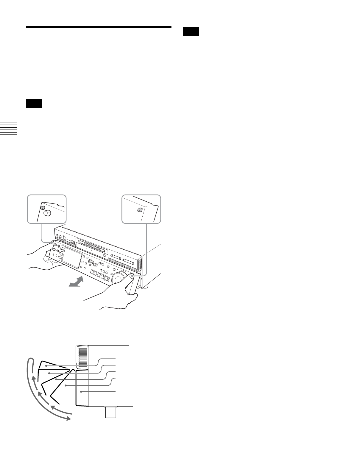
Front Panel Tilt Mechanism
The front panel of this unit has a tilt mechanism that allows
you to pull the front panel out and adjust it to a convenient
angle.
Note
Do not adjust the tilt during recording, playback, or
copying. Shocks or vibrations can affect the internal
storage, preventing normal recording, playback, or
Chapter 3 Preparations
copying.
Before adjusting the tilt, be sure to put the unit into stop
mode.
To pull the front panel out
Press and hold in the lock release buttons on both sides of
the front panel, and pull in the direction of the arrow.
Note
The angle cannot be fixed if you pull the front panel past
position 3 all the way out to the return position. To fix the
front panel, return it to position 0 and then pull it out to the
desired angle.
To return the front panel to its original
position
Unlock the front panel by pulling it out to the return
position. You can then return it to position 0.
To change the angle of the front panel
To change to a larger angle, pull the panel up to that angle.
To change to a smaller angle, pull the front panel all the
way up to the return position, releasing the lock. Then
return it to position 0 and pull it out again to the desired
angle.
You can fix the angle of the front panel in position 1 (40
degrees), position 2 (65 degrees), or position 3 (90
degrees).
Return position
Position 3 (90 degrees)
Position 2 (65 degrees)
Position 1 (40 degrees)
Position 0
30
Front Panel Tilt Mechanism
 Loading...