

Page 1

PROFESSIONAL MEDIA STATION
XDS-PD1000
XDS-PD2000
OPERATION MANUAL [English]
1st Edition
Page 2

WARNING
To reduce the risk of fire or electric shock,
do not expose this apparatus to rain or
moisture.
To avoid electrical shock, do not open the
cabinet. Refer servicing to qualified
personnel only.
3. Internal air ambient temperature of the rack
When this product is installed in a rack, please make sure
that the internal air ambient temperature of the rack is within
the specified limit of this product.
4. Prevention against achieving hazardous condition due
to uneven mechanical loading
When this product is installed in a rack, please make sure
that the rack does not achieve hazardous condition due to
uneven mechanical loading.
THIS APPARATUS MUST BE EARTHED.
When installing the unit, incorporate a readily accessible
disconnect device in the fixed wiring, or connect the power
plug to an easily accessible socket-outlet near the unit. If a
fault should occur during operation of the unit, operate the
disconnect device to switch the power supply off, or
disconnect the power plug.
WARNING: THIS WARNING IS APPLICABLE FOR USA
ONLY.
If used in USA, use the UL LISTED power cord specified
below.
DO NOT USE ANY OTHER POWER CORD.
Plug Cap Parallel blade with ground pin
(NEMA 5-15P Configuration)
Cord Type SJT, three 16 or 18 AWG wires
Length Minimum 1.5 m (4 ft. 11 in.),
Less than 2.5 m (8 ft. 3 in.)
Rating Minimum 10 A, 125 V
Using this unit at a voltage other than 120 V may require the
use of a different line cord or attachment plug, or both. To
reduce the risk of fire or electric shock, refer servicing to
qualified service personnel.
5. Install the equipment while taking the operating
temperature of the equipment into consideration
For the operating temperature of the equipment, refer to the
specifications of the Operation Manual.
6. When performing the installation, keep the following
space away from walls in order to obtain proper
exhaust and radiation of heat.
Right, Left: 4 cm (1.6 inches) or more
Rear: 10 cm (4 inches) or more
When installing the installation space must be secured in
consideration of the ventilation and service operation.
• Do not block the fan exhaust areas (rear panel and rear part
of the right side panel) and vents (front panel, front lower
part, and front right and left ends) with objects.
• Leave a space around the unit for ventilation.
• Leave more than 10 cm of space in the rear of the unit to
secure the operation area.
When the unit is installed on the desk or the like, leave at least
4 cm of space in the left and right sides. Leaving 40 cm or
more of space above the unit is recommended for service
operation.
WARNING: THIS WARNING IS APPLICABLE FOR OTHER
COUNTRIES.
1. Use the approved Power Cord (3-core mains lead)/
Appliance Connector/Plug with earthing-contacts that
conforms to the safety regulations of each country if
applicable.
2. Use the Power Cord (3-core mains lead)/Appliance
Connector/Plug conforming to the proper ratings (Voltage,
Ampere).
If you have questions on the use of the above Power Cord/
Appliance Connector/Plug, please consult a qualified service
personnel.
Attention-when the product is installed in Rack:
1. Prevention against overloading of branch circuit
When this product is installed in a rack and is supplied
power from an outlet on the rack, please make sure that the
rack does not overload the supply circuit.
2. Providing protective earth
When this product is installed in a rack and is supplied
power from an outlet on the rack, please confirm that the
outlet is provided with a suitable protective earth
connection.
This Professional Media Station is classified as a CLASS 1
LASER PRODUCT.
Tämä ammattimainen media-asema on luokiteltu 1. LUOKAN
LASERTUOTTEEKSI.
Denna mediastation för professionella klassificeras som en
LASERPRODUKT AV KLASS 1.
Laser Diode Properties
Wavelength: 400 to 410 nm
Emission duration: Continuous
Laser output power: 280 mW (max. of pulse peak), 150 mW
(max. of CW)
Standard: IEC60825-1 (2007)
Egenskaber for laserdiode
Bølgelængde: 400 till 410 nm
Strålingsvarighed: Kontinuerlig
Afgivet lasereffekt: 280 mW (max. för pulstopp), 150 mW
(max. för kontinuerlig våg)
Standard: IEC60825-1 (2007)
2
Page 3
Egenskaber for laserdiode
Bølgelengde: 400 till 410 nm
Strålingsvarighed: Uavbrutt
Utgangseffekt for laser: 280 mW (maks stråletoppunkt), 150
mW (maks ved kontinuerlig stråling)
Standard: IEC60825-1 (2007)
Laserdiod Egenskaper
Våglängd: 400 - 410 nm
Strålningens varaktighet: Continuous
Lasereffekt: 280 mW (sykehuipun maks.), 150 mW
(jatkuvan aallon maks.)
Standard: IEC60825-1 (2007)
This label is located on the top panel of the drive unit.
Denna etikett finns på ovansidan av driftenheten.
Denne mærkat sidder på drevenhedens øverste panel.
Tämä kyltti sijaitsee ajurilaitteen yläpinnalla.
Dette merket er plassert på oversiden av driverenheten.
user will be required to correct the interference at his own
expense.
You are cautioned that any changes or modifications not
expressly approved in this manual could void your authority to
operate this equipment.
All interface cables used to connect peripherals must be
shielded in order to comply with the limits for a digital device
pursuant to Subpart B of Part 15 of FCC Rules.
This device complies with Part 15 of the FCC Rules. Operation
is subject to the following two conditions: (1) this device may
not cause harmful interference, and (2) this device must
accept any interference received, including interference that
may cause undesired operation.
For customers in Canada
This Class A digital apparatus complies with Canadian ICES-
003.
For the customers in Europe
This product with the CE marking complies with the EMC
Directive issued by the Commission of the European
Community.
Compliance with this directive implies conformity to the
following European standards:
• EN55103-1: Electromagnetic Interference(Emission)
• EN55103-2: Electromagnetic Susceptibility(Immunity)
This product is intended for use in the following
Electromagnetic Environments: E1 (residential), E2
(commercial and light industrial), E3 (urban outdoors), E4
(controlled EMC environment, ex. TV studio).
CAUTION
The use of optical instruments with this product will increase
eye hazard.
Use of controls or adjustments or performance of procedures
other than those specified herein may result in hazardous
radiation exposure.
VAROITUS!
LAITTEEN KÄYTTÄMINEN MUULLA KUIN TÄSSÄ
KÄYTTÖOHJEESSA MAINITULLA TAVALLA SAATTAA
ALTISTAA KÄYTTÄJÄN TURVALLISUUSLUOKAN 1
YLITTÄVÄLLE NÄKYMÄTTÖMÄLLE LASERSÄTEILYLLE.
VARNING
OM APPARATEN ANVÄNDS PÅ ANNAT SÄTT ÄN I DENNA
BRUKSANVISNING SPECIFICERATS, KAN ANVÄNDAREN
UTSÄTTAS FÖR OSYNLIG LASERSTRÅLNING, SOM
ÖVERSKRIDER GRÄNSEN FÖR LASERKLASS 1.
For the customers in the USA
This equipment has been tested and found to comply with the
limits for a Class A digital device, pursuant to Part 15 of the
FCC Rules. These limits are designed to provide reasonable
protection against harmful interference when the equipment is
operated in a commercial environment. This equipment
generates, uses, and can radiate radio frequency energy and,
if not installed and used in accordance with the instruction
manual, may cause harmful interference to radio
communications. Operation of this equipment in a residential
area is likely to cause harmful interference in which case the
The manufacturer of this product is Sony Corporation, 1-7-1
Konan, Minato-ku, Tokyo, Japan.
The Authorized Representative for EMC and product safety is
Sony Deutschland GmbH, Hedelfinger Strasse 61, 70327
Stuttgart, Germany.
For kundene i Norge
Dette utstyret kan kobles til et IT-strømfordelingssystem.
For the State of California, USA only
Perchlorate Material - special handling may apply, See
www.dtsc.ca.gov/hazardouswaste/perchlorate
Perchlorate Material : Lithium battery contains perchlorate.
For the Customers in Taiwan only
3
Page 4

Table of Contents
Chapter 1 Overview
Features............................................................................................8
Features of this unit ............................................................................... 8
System Configurations .................................................................11
Satellite news gathering (SNG) system............................................... 12
Ingesting/editing system...................................................................... 12
Live production system ....................................................................... 13
Delivery system................................................................................... 13
Chapter 2 Names and Functions of Parts
Front Panel .....................................................................................14
Display screen ..................................................................................... 20
Rear Panel ......................................................................................24
Chapter 3 Preparations
Supplying Power............................................................................28
Initial Setup ....................................................................................28
Front Panel Tilt Mechanism..........................................................30
Connections and Settings ............................................................31
Synchronization Reference Signals.............................................36
Setting System Frequency............................................................37
Setting Time Data ..........................................................................37
Superimposed Text Information...................................................39
Basic Operations of the Function Menu......................................41
Handling Discs...............................................................................44
Connections for using XDCAM Browser or a nonlinear editor that is not
a Sony product ........................................................................... 31
Connections for cut editing ................................................................. 32
Setting timecode .................................................................................. 37
Setting user bits ................................................................................... 39
Function menu operations ................................................................... 41
Function menu settings........................................................................ 41
Discs used for recording and playback................................................ 44
4
Table of Contents
Page 5

Notes on handling ................................................................................44
Write-protecting discs.......................................................................... 44
Loading and unloading a disc.............................................................. 44
Formatting a disc ................................................................................. 45
Handling SxS Memory Cards ....................................................... 45
About SxS memory cards .................................................................... 45
Inserting/removing an SxS memory card ............................................ 46
Switching between SxS memory cards................................................ 47
Chapter 4 Recording, Playback and Copying
Recording....................................................................................... 48
Preparations for recording ...................................................................48
Carrying out recording......................................................................... 48
Mixed recording of clips in different formats on the same disc .......... 49
Playback.........................................................................................50
Selecting a clip or an EDL................................................................... 51
Playback operation............................................................................... 51
Playback operations using thumbnails................................................. 53
Chase play............................................................................................ 53
Copying .......................................................................................... 54
Overview.............................................................................................. 54
Copy operations ...................................................................................54
Chase copy........................................................................................... 56
Chapter 5 Operations in Clip List Screens
Overview......................................................................................... 58
Switching between display screens ..................................................... 58
Information and controls in clip list screens........................................ 59
Clip Menu ............................................................................................ 61
Clip F Menu......................................................................................... 62
Clip Operations.............................................................................. 63
Selecting clips...................................................................................... 63
Searching with thumbnails .................................................................. 63
Setting clip flags .................................................................................. 64
Locking (write-protecting) clips ..........................................................64
Deleting clips ....................................................................................... 64
Copying clips....................................................................................... 65
Setting the index picture frame............................................................ 65
Disc Operations............................................................................. 66
Table of Contents
5
Page 6

Formatting (initializing) discs ............................................................. 66
Finalizing discs.................................................................................... 66
Chapter 6 File Operations
Overview.........................................................................................67
Directory structure............................................................................... 67
File operation restrictions.................................................................... 67
FTP File Operations.......................................................................69
Making FTP connections..................................................................... 69
Command list ...................................................................................... 69
CIFS File Operations .....................................................................73
Making CIFS connections ................................................................... 73
Chapter 7 Menus
Appendix
Menu System Configuration .........................................................74
Setup Menu ....................................................................................74
Items in the basic menu ....................................................................... 75
Basic menu operations......................................................................... 77
Items in the extended menu................................................................. 79
Extended menu operations .................................................................. 90
Maintenance Menu.........................................................................92
Items in the maintenance menu ........................................................... 92
Maintenance menu operations............................................................. 96
Important Notes on Operation......................................................98
About the LCD panel .......................................................................... 98
Condensation ....................................................................................... 98
Precautions for products with built-in HDD ....................................... 99
Periodic Maintenance..................................................................100
Operating hours meter ....................................................................... 100
Troubleshooting ..........................................................................101
Alarms ............................................................................................... 101
Error messages .................................................................................. 107
Specifications ..............................................................................108
6
Table of Contents
Page 7

About DVB-ASI Input/Output (When the Optional PDBK-202 Is
Used)......................................................................................111
Using UMID Data.......................................................................... 113
Correspondence between Setting Items of the HKDV-900 and
Setup Menu of This Unit....................................................... 114
Trademarks and Licenses .......................................................... 115
MPEG-4 visual patent portfolio license ............................................ 115
MPEG-2 video patent portfolio license ............................................. 115
About IJG (Independent JPEG Group).............................................. 116
Character display software “iType”................................................... 116
Open software licenses ...................................................................... 116
Obtaining GPL/LGPL/GPL V3 licensed software ............................ 116
Glossary .......................................................................................117
Index ............................................................................................ 119
Table of Contents
7
Page 8

Chapter 1 Overview
Overview
Features
Chapter
PD1000
HDDs for internal storage
1
The XDS-PD1000/PD2000 is a full-HD (1920 × 1080 and
1280 × 720) hybrid media deck that can use an internal
storage, Professional Discs, and SxS memory cards as
recording media.
The XDS-PD1000 is equipped with hard disk drives
(“HDDs” below) as internal storage.
The XDS-PD2000 is equipped with solid state drives
(“SDDs” below) as internal storage.
Compared to conventional studio decks, the XDS-PD1000
features better support for multitasked operation,
networking, and other IT functions. It is highly compatible
with nonlinear editing systems and network production
systems, enabling efficient file-based operation.
You can connect this unit via the standard HD-SDI I/O
connectors to devices provided with HD-SDI interfaces,
including conventional nonlinear editors, monitors, and
other video equipment. This allows you to use this unit as
a video editing or playout player, and as a recorder for
nonlinear editing.
Features of this unit
The principal features of this unit are as follows.
MPEG HD422
1)
codec
Long recording times
This unit is equipped with HDDs for internal storage.
These HDDs provide 1 terabyte (TB) of data storage,
allowing you to record up to about 30 hours in the HD422
50 Mbps recording format.
High reliability
This unit is equipped with three HDDs (Data: 2 HDDs;
Fault tolerance: 1 HDD), configured for high reliability as
a RAID-4
It can also be equipped with a redundant power supply.
1) RAID-4: Redundant Arrays of Inexpensive Disks Level 4
2) When the optional XDBK-101 is installed. (It is necessary to set the
maintenance menu item M22: OPTION SETTING >DVB-ASI to “ON”.)
PD2000
1)
array.
2)
SDDs for internal storage
Long recording times
This unit is equipped with SDDs as internal storage. These
SSDs provide 512 GB of data storage, allowing you to
record up to about 16 hours in the HD422 50 Mbps
recording format.
High reliability
This unit is equipped with two SSDs, which can be
configured for high reliability as a RAID-4
It can also be equipped with a redundant power supply.
1)
array.
2)
3)
High-quality video and audio recording and
playback
The MPEG HD422 codec provides video compression
compliant with the MPEG-2 422P@HL standard. It
enables HD 4:2:2 (50 Mbps) digital component file
recording in the 1080i (1080 effective scanning lines,
interlaced) or 720P (720 effective scanning lines,
progressive) format.
Uncompressed PCM recording of 24-bit 48 kHz audio
enables 8-channel audio recording at high sound quality.
1) MPEG HD422 is a trademark of Sony Corporation.
8
Features
1) RAID-4: Redundant Arrays of Inexpensive Disks 4
2) When the optional XDBK-102 is installed. (It is necessary to set the
maintenance menu item D11: RAID to “on”.)
3) When the optional XDBK-101 is installed. (It is necessary to set the
maintenance menu item M22: OPTION SETTING >DVB-ASI to “ON”.)
High performance
Equipped with high-speed SSDs as internal storage and a
high-performance CPU, this unit has the following
advantages over the XDS-1000/XDS-PD1000.
• Quicker response during playback
• Higher speed in multitasked operation
Page 9
• Direct control for editing from a nonlinear editor using
CIFS PROTOCAL
Multitasking operation
Chase play
You can perform chase play of material being recorded.
Support for multiple network connection
sessions, and the chase transfer facility
It is possible to individually control multiple sessions
using FTP/CIFS protocol (XDS-PD1000: up to eight
sessions; XDS-1000: up to four sessions).
You can use FTP/CIFS protocol to transfer the material
being recorded (the chase transfer function).
The XDS-PD2000 allows for direct access to material on
the SSD using CIFS protocol. It also allows for a “chase
editing” function, enabling the material being recorded to
be laid on the timeline.
Multifunction operations
You can perform the following operations in parallel on
individual clips.
• Record signals input to the HD/SD-SDI INPUT
connector to internal storage
• Copy to internal storage from Professional Discs/SxS
memory cards
• Copy from internal storage to Professional Discs
• Play clips that have been recorded to the internal storage/
Professional Discs
• Upload and download via FTP/CIFS connections
The XDS-PD2000 makes it possible to perform a copy/
network transfer operation at higher speeds than the
XDS-1000/XDS-PD1000.
Recording and playback functions
Support for multiple SD/HD codecs
In addition to the MPEG HD422 codec, this unit supports
the MPEG HD codec.
component files at both 1080i (35/25/18 Mbps
720P (35/25 Mbps
wide range of recording times and application objectives.
It can also record SD files (at IMX30/40/50 Mbps
DVCAM codec).
1) MPEG HD is a registered trademark of Sony Corporation.
2) SDI recording only supported for 35 Mbps, and playback only supported
for 25 Mbps and 18 Mbps.
3) SDI recording only supported for 50 Mbps.
Support for multiple frame frequencies
This unit can record and play at multiple frame
frequencies: 1080/59.94i, 50i, 29.97P, 25P, and 23.98P or
720/59.94P and 50P (for MPEG HD422).
1)
It can record HD 4:2:0 digital
2)
), allowing HD operation across a
2)
) and
3)
or by
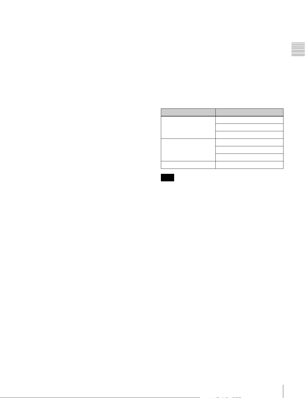
Support for mixed format recording mode
You can record clips to the internal storage at different
system frequencies and in different formats (HD422/
HD420).
As long as the frame frequency group is the same, clips in
different recording formats can be recorded or written to
the same Professional Disc.
1) The recording format is regarded as different whenever the system
frequency, video resolution, video codec/bit rate, or number of audio
channels or number of bits does not match.
1)
The system frequencies supported by this unit are divided
into frame frequency groups, as shown in the following
table.
Frame frequency group System frequency
59.94 Hz 59.94P
59.94i
29.97P
50 Hz 50P
50i
25P
23.98 Hz 23.98P
Note
Continuous playback may not be possible at the transition
point between two clips with different recording formats.
Simultaneous recording to the internal storage
and a Professional Disc
This unit allows for simultaneous recording to the internal
storage and a Professional Disc.
(Simultaneous recording can be performed by
simultaneously executing recording to the internal storage
and copying from the internal storage to the Professional
Disc.)
SD upconvert function
The unit is provided with an upconvert function.
You can input SD signals to the HD/SD-SDI INPUT
connector and record them as HD signals.
HD downconvert function
The unit is provided with a downconvert function. HD clip
playback signals can be downconverted to SD signals and
then output as SD-SDI or composite signals. This allows
you to use this unit for editing and program output in an SD
environment.
1080/720 cross-conversion
This unit supports cross-conversion output. It can output
720 while playing media recorded as 1080, and output
1080 while playing media recorded as 720.
Chapter 1 Overview
Features
9
Page 10

Recording of proxy AV data
Proxy AV data is a low-resolution (1.5 Mbps video, 64
kbps per audio channel), MPEG-4 based version of a full
resolution data stream. Whenever this unit records video
signals input to the HD/SD-SDI INPUT connector, it
simultaneously generates and records low-resolution
Chapter 1 Overview
proxy AV data.
1) Proxy AV data is not generated when you copy MP4 clips to internal
storage from SxS memory cards or copy to internal storage via an FTP/
CIFS connection.
1)
High-speed searches with the shuttle/jog dial
The shuttle/jog dial can be used to find scenes inside clips
on the internal storage/Professional Discs, in the same way
as the shuttle and jog dials on conventional VTRs.
In variable-speed mode, you can search in field units at
from –2 to +2 times normal speed. Shuttle mode supports
high-speed searches up to a maximum of ±20 times normal
speed.
Convenient playback and searching
Like previous products in the XDCAM series, this unit
supports convenient search functions, including thumbnail
searches.
1)
1)
1)
• HD-SDI video, 8-channel audio input and output
• HD-SDI video, 8-channel audio monitor output
• SD-SDI video, 8-channel audio input and output
• SD-SDI video, 8-channel audio monitor output
• SD composite output
• SD composite monitor output
• DVB-ASI TS input and output
2)
• AES/EBU digital audio 4-channel input and output
• Analog audio 2-channel input and output
• Analog audio 2-channel monitor output
• HDMI output
• Monitor output (VGA)
• Timecode input and output
• System timecode input
• Remote control
- RS-422A (D-sub 9-pin) (2)
(In addition to the Sony 9-pin VTR protocol, this unit
supports the Video Disk Control Protocol (VDCP).)
- Video remote (D-sub 9-pin) (1)
- GPIO (D-sub 15-pin) (1)
(4 inputs and 4 outputs)
1) The HD/SD-SDI INPUT connector doubles as an HD-SDI input connector
and an SD-SDI input connector.
2) With an optional PDBK-202 installed.
Networking
File transfer functions
This unit is equipped with a Gigabit Ethernet connector,
allowing you to perform high-speed file transfers of the
video, audio, and metadata on internal storage using FTP
and other standard protocols.
Network control
You can control this unit via a network by using the
network remote connection. The unit supports traditional
remote control via remote control connectors such as the
RS422 and GPIO connectors. In addition, the high-speed
network interface to external devices enables control by
various other applications, for acquisition of file lists and
display of thumbnails.
Usability enhancements and rich selection
of interfaces
Color LCD display
The unit is equipped with a 16:9, 4.3-inch color LCD
which allows you to check the contents of the media and
use the menu system without connecting an external
monitor.
Tiltable front panel
The front panel is tiltable for easy rack-mount and desktop
operation. You can adjust the panel to the angle that makes
the buttons easiest to use.
Supports a variety of interfaces
This unit supports the following interfaces.
10
Features
Page 11
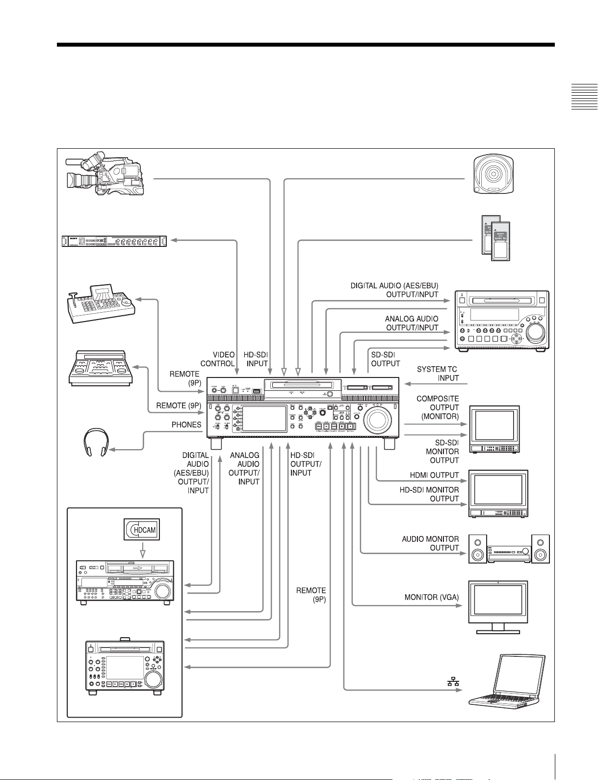
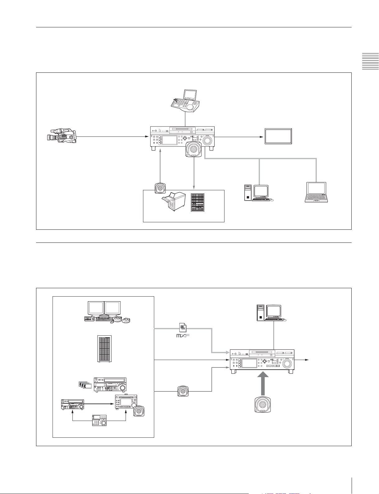
System Configurations
The figure below shows devices and media that can be
used with this unit.
You can use this unit and these devices to configure the
following systems.
PDW-700/PMW-500
HKDV-900 Video Control Unit
VDCP controller
• Satellite news gathering (SNG) system (see page 12)
• Ingesting/editing system (see page 12)
• Live production system (see page 13)
• Broadcast delivery system (see page 13)
Professional Disc
SxS memory cards
• SxS PRO
•SxS-1
PDW-1500
Chapter 1 Overview
BVE-700
Headphones
HDW-2000 series
Standard reference
timecode
SD video monitor
HD video monitor
Audio monitor
PC monitor
PDW-F1600/HD1500
Laptop computer
System Configurations
11
Page 12
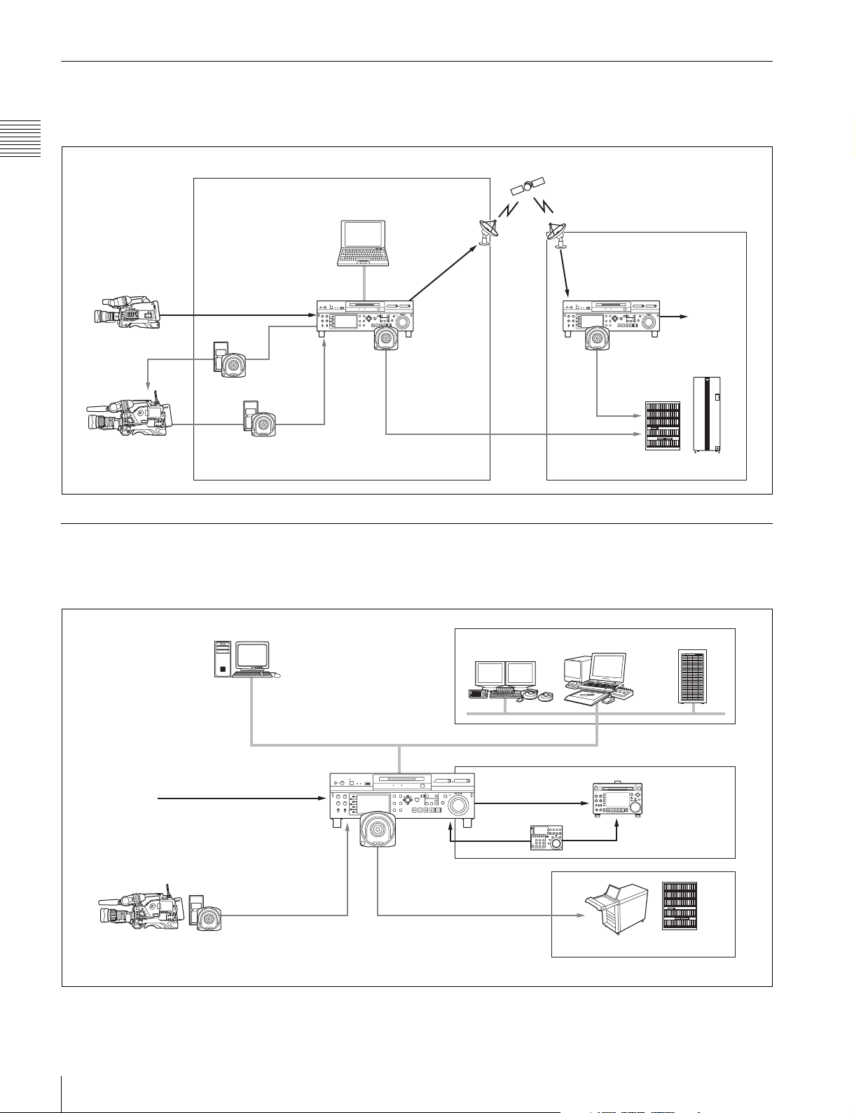
Satellite news gathering (SNG) system
The following figure shows an example of SNG system in
which this unit is used as both server and backup recorder.
Chapter 1 Overview
Camcorder
Camcorder
On the satellite truck
Reuse media
Save to internal storage
Ingesting/editing system
SDI signal
This unit
Computer
DVB-ASI
TS signal
Save clips
(installed with XDCAM Browser)
DVB-ASI
TS signal
This unit
Playout
Save clips
Archive system
The following figure shows an example of system in which
this unit is used as both editing feeder and backup recorder.
Computer (ingestion controller)
Remote control (via
Line input
Camcorder
Internet Protocol/
Web Service API)
SDI/DVB-ASI TS signal
Recording data
Global Ethernet
This unit
Save clips
Nonlinear editing system
Linear editing system
SDI signal
RS422
Server
FTP/CIFS
PDW-F1600
(recorder)
Archive system
12
System Configurations
Page 13
Live production system
The following figure shows an example of sports relay or
live recording system in which this unit is used as both
editing feeder and backup recorder.
Slow-motion/replay controller
Chapter 1 Overview
This unit
Live video (SID signal)
Camcorder
Read in video
from library
Save
recorded clips
Archive/library system
Delivery system
The following figure shows an example of program
delivery system in which this unit is used as both server
and backup player.
RS422 (VDCP)
FTP/CIFS
SDI signal
Global Ethernet
Nonlinear editing
system (pre-/postediting)
Monitor
Slow-motion/
replay video
Computer (XDCAM
Browser installed)
Nonlinear editing system
Material server
Recording system
MXF file
SDI signal
Save clips
Global Ethernet
This unit
Play out emergency video directly
from Professional Disc
Computer (program
transmission controller)
RS422 (VDCP)
Playout
System Configurations
13
Page 14
Names and Functions of
Parts
Chapter 2 Names and Functions of Parts
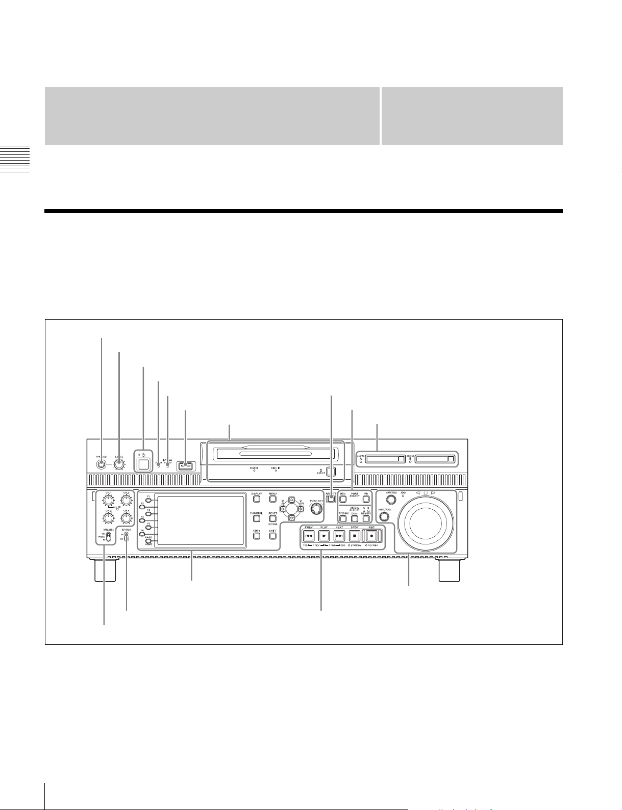
Front Panel
The names and symbols of buttons and knobs on the front
panel are color coded according to function.
White: Function when the button or knob is operated
independently.
1 PHONES jack
2 LEVEL adjustment knob
3 On/standby (1) button and indicator
4 ALARM indicator
5 INTERNAL ACCESS indicator
6 MAINTENANCE connector
2 Disc control section
(see page 16)
Chapter
Orange: Function when the button is operated with the
SHIFT button held down.
Blue: Function related to thumbnail operations.
7 REMOTE button
1 Port and media selection section (see page 15)
3 Memory card slots (see page 16)
2
5 Display/menu control
section (see page 17)
8 KEY INHI switch
4 Audio level adjustment section (see page 16)
a PHONES jack
This is a standard stereo jack. Connect stereo headphones
to monitor the audio during recording and playback. (Nonaudio signals are muted.) The monitored channel is
selected with MONITR L and MONITR R on the HOME
page of the function menu (see page 41).
14
Front Panel
7 Shuttle/jog/variable-speed playback
control section (see page 19)
6 Recording and playback control section (see page 18)
b LEVEL (volume) adjustment knob
Adjust the volume of headphones with this knob. You can
also cause this knob to simultaneously adjust the output
volume from the AUDIO MONITOR OUTPUT R, L
connectors on the rear panel. To do this, set setup menu
item 114 AUDIO MONITOR OUTPUT LEVEL to
“variable”.
Page 15
c On/standby (1) button and indicator
When the main power switch on the rear panel is in the on
position, this switches the unit between the operating state
(the indicator is lit green) and the standby state (the
indicator is lit red).
To put the unit into the operating state, press this button
and hold it down for a short time (0.25 seconds or longer)
while the indicator is lit red. The indicator changes to lit
green, and the unit enters the operating state.
To put the unit into the standby state, press this button and
hold it down for a longer time (1 second or longer) while
the indicator is lit green. The indicator changes to flashing
green and then lit red, and the unit enters the standby state.
When using this unit, normally leave the main power
switch on the rear panel in the on position, and use this
button to switch the unit between the operating state and
standby state.
Note
To switch the state of this unit from standby state (the main
switch on the rear panel is on) to operative state, wait at
least three seconds after the unit has entered standby state
and then press the on/standby button on the front panel.
d ALARM indicator
This flashes to alert you to an error in the unit, and goes out
when the cause of the error is removed.
Flashing red: An error that requires service has occurred,
in most cases a hardware error.
Flashing orange: A warning level error has occurred.
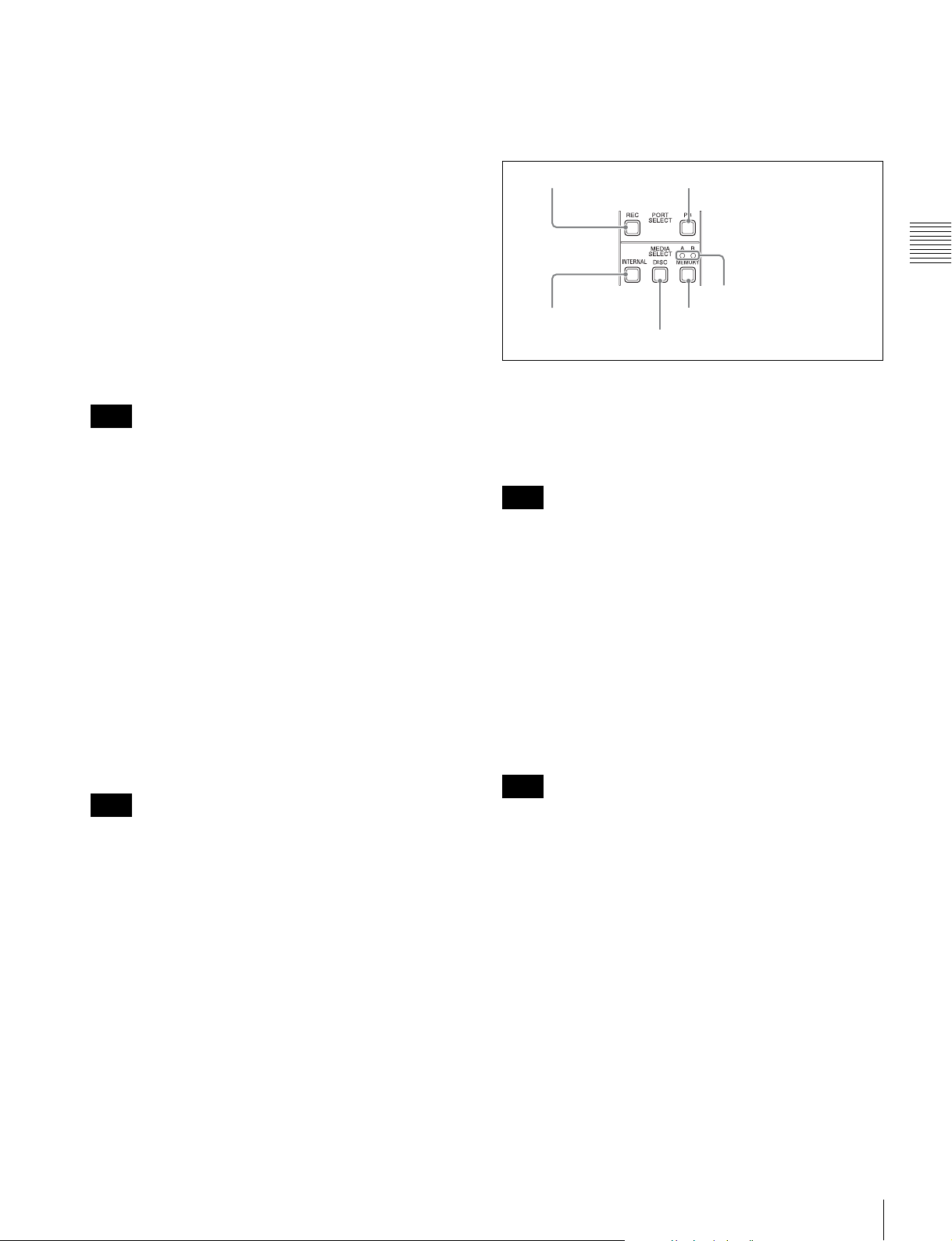
1 Port and media selection section
This unit has a recording port and a playback port. You can
control these ports independently by selecting one of them
with the REC PORT or PB PORT button.
1 REC PORT button
3 INTERNAL
button
a REC PORT (recording port) button
Before performing recording operations on the front panel
of this unit, press this button to select the recording port.
E-E signals (the video of the input signals) are output to the
display and to the video monitor output connectors.
Note
When a clip list screen is displayed, pressing this button
does not output E-E signals to the display. To operate this
button, first press the THUMBNAIL button to switch to
the basic operation screen or the video monitor screen.
Even when a clip list screen is displayed, pressing this
button switches the output signals of the video monitor
output connectors to E-E signals.
2 PB PORT button
6 Slot selection lamps
5 MEMORY button
4 DISC button
Chapter 2 Names and Functions of Parts
A message appears on the display when this indicator
starts flashing. For details, see “Troubleshooting”
(page 101).
e INTERNAL (internal storage) ACCESS indicator
This lights when the internal storage is accessed.
Note
Do not turn off the main power switch on the rear panel or
disconnect the power cord while the INTERNAL
ACCESS indicator is lit. Doing so may corrupt the data on
the storage.
f MAINTENANCE connector
This is the USB connector for maintenance.
g REMOTE button
Press this button, turning it on, to perform remote control
of this unit from a device connected to the REMOTE (9P)
1 and 2 connectors.
This allows you to control the recording and playback
ports individually.
h KEY INHI (inhibit) switch
This turns key operation inhibit mode on or off.
b PB PORT (playback port) button
Before performing playback operations on the front panel
of this unit, press this button to select the playback port.
Playback video is output to the display and to the video
output connectors/video monitor connectors.
Note
When a clip list screen is displayed, pressing this button
does not output playback signals to the display or video
output connectors. To operate this button, first press the
THUMBNAIL button to switch to the basic operation
screen or the video monitor screen.
Even when a clip list screen is displayed, pressing this
button switches the output signals of the video monitor
output connectors to playback video signals.
c INTERNAL (internal storage) button
This button selects internal storage as the operation target
media.
d DISC button
This button selects a Professional Disc as the operation
target media.
Front Panel
15
Page 16
e MEMORY button
This button selects an SxS memory card as the operation
target media.
a Memory card slots
These two slots (A and B) can receive SxS memory cards
(see page 46).
f Slot selection lamps
These light to indicate the selected memory card slot.
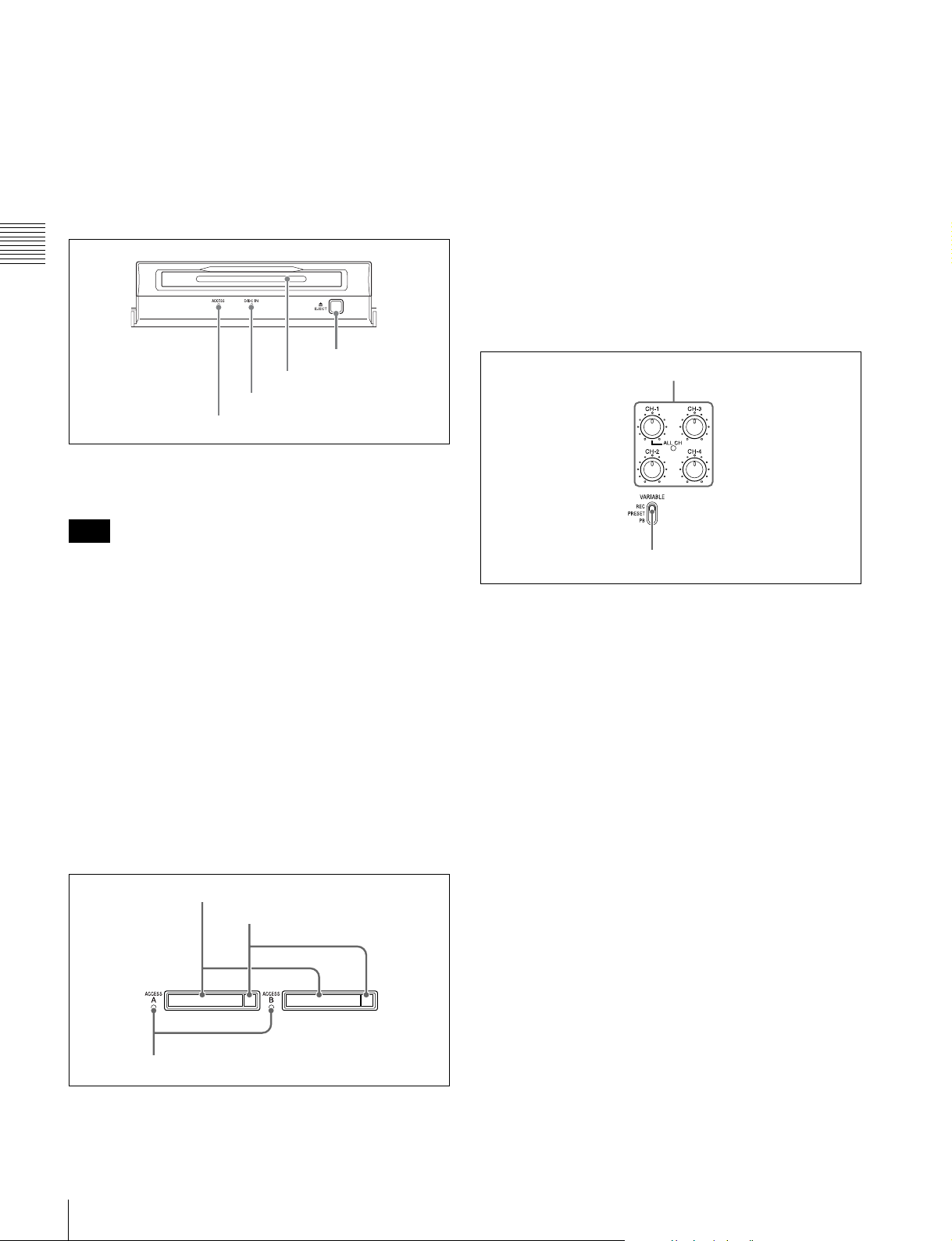
2 Disc control section
Chapter 2 Names and Functions of Parts
4 EJECT button
3 Disc slot
2 DISC IN indicator
1 DISC ACCESS indicator
a DISC ACCESS indicator
This lights when the Professional Disc is accessed.
Note
While the ACCESS indicator is lit, do not turn off the main
power switch on the rear panel or disconnect the power
cord.
This could lead to a loss of data from the disc.
b DISC IN indicator
This lights when a Professional Disc is inserted.
c Disc slot
Insert a Professional Disc in this slot (see page 44).
d EJECT button
To remove the Professional Disc, press this button (see
page 44).
3 Memory card slots
b Eject buttons
To remove the SxS memory card from the slot, press the
eject button to release the lock, then press the button once
more. This makes the media come out of the slot partially
(see page 47).
c MEMORY ACCESS A/B lamps
Indicate the state of slots A and B (see page 47).
4 Audio level adjustment section
1 CH-1/ALL CH, CH-2 to CH-4 adjustment knobs
2 VARIABLE switch
a CH-1/ALL CH, CH-2 to CH-4 (audio level)
adjustment knobs
Depending on the setting of the VARIABLE switch, these
adjust the input audio or playback audio levels of channels
1 to 4.
You can adjust levels of channels 5 to 8 using the function
menu. For details, see “P3 AUDIO page” (page 43).
By the setting of setup menu item 131 AUDIO VOLUME,
you can enable the CH-1/ALL CH adjustment knob to
simultaneously adjust all eight channels. When this
simultaneous adjustment is enabled, the ALL CH indicator
lights.
16
Front Panel
1 Memory card slots
2 Eject buttons
3 MEMORY ACCESS A/B lamps
b VARIABLE (audio level adjustment selector)
switch
This selects whether input audio levels or playback audio
levels are adjusted by the CH-1/ALL CH and CH-2 to CH4 adjustment knobs for channels 1 to 4, or by the function
menu setting for channels 5 to 8.
REC: Adjust the input audio levels. The playback audio
levels are fixed at their preset values.
PRESET: The audio levels are fixed at their preset values.
PB: Adjust the playback audio levels. The input audio
levels are fixed at their preset values.
Page 17
Note
It is not possible to adjust the audio levels of the recording
and playback ports simultaneously.
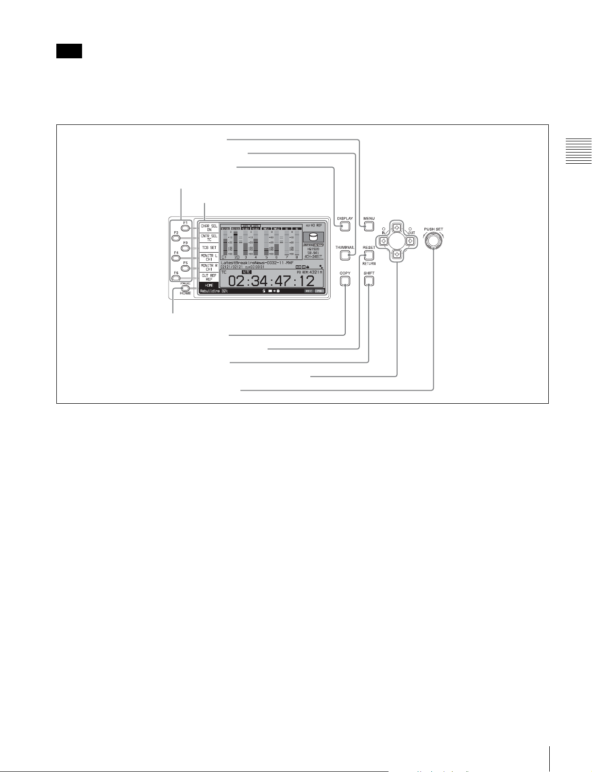
5 Display/menu control section
5 MENU button
4 THUMBNAIL button
3 DISPLAY button
1 Function buttons (F1 to F6)
2 Display
6 PAGE/HOME button
To set the audio level of each port separately, adjust one or
the other by using external audio equipment connected to
a REMOTE (9P) connector (1 or 2).
Chapter 2 Names and Functions of Parts
7 COPY button
8 RESET/RETURN button
9 SHIFT button
q; Arrow buttons and IN/OUT indicators
qa PUSH SET knob
a Function buttons (F1 to F6)
These buttons are enabled when the function menu (see
page 41) is visible. Each press of a button changes the
setting of the corresponding item in the menu.
When the setup menu (see page 77) is displayed, these
buttons function as menu control buttons.
For convenience, this manual refers to these buttons as
buttons F1 to F6, in order from the top.
b Display
Displays video being recorded, E-E video, playback video,
menus, audio level meters, and data such as timecode or
clip information. It can be switched between a basic
operation screen (see page 20), a video monitor screen (see
page 23), and a clip list screen (see page 59).
For details, see page 58.
c DISPLAY button
Each press of this button switches between the basic
operation screen, the video monitor screen, and the clip list
screen (see page 58).
When the clip list screen is displayed, this button switches
the display between thumbnails view and details view.
d THUMBNAIL button
When this button is pressed when the basic operation
screen or video monitor screen is displayed, a list of clips
saved on the currently selected media is displayed. (That
is, the current screen is switched to a clip list screen.)
When pressed again, returns to the basic operation screen
or the video monitor screen.
e MENU button
Starts the setup menu, and starts the Clip Menu from a clip
list screen (see page 61). The same information is also
superimposed on the display on a video monitor connected
to the unit. When pressed again, the setup menu or the Clip
Menu disappears.
f PAGE/HOME button
When pressed alone, functions as the PAGE button. When
pressed together with the SHIFT button, functions as the
HOME button.
PAGE button: Displays the function menu, if it is not
visible. (The most recently displayed page of the
function menu appears.)
HOME button: When pressed with the function menu
visible, returns to the HOME page of the function
menu.
Front Panel
17
Page 18
g COPY button
Displays the Clip Copy screen. (see page 55).
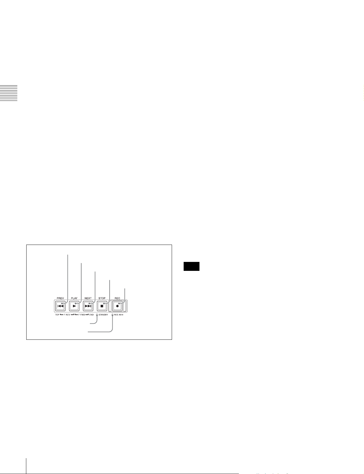
b PLAY button
To start playback, press this button, turning it on.
h RESET/RETURN button
Functions as the RESET button or the RETURN button.
RESET button: Resets counters or the setting values of
the timecode generator.
RETURN button: In clip list screens, returns to the
previous procedure.
i SHIFT button
Chapter 2 Names and Functions of Parts
Switches between functions for any button with two
functions.
j Arrow buttons and IN/OUT indicators
The arrow buttons are used for clip selection, menu setting
operations, and so on.
When you use the arrow buttons to set an IN and OUT
point in the clip, it becomes possible to copy only the part
defined by the IN and OUT points (see page 56). When an
IN and OUT points are set in the clip, the IN and OUT
indicators light.
k PUSH SET knob
This is used for menu operations and thumbnail operations
in a clip list screen. Turn the knob to select items, and press
it to confirm the selection. This button is also used to set
numerical and timecode values.
6 Recording and playback control section
1 PREV button
2 PLAY button
3 NEXT button
4 STOP button
5 REC button
7 STANDBY indicator
6 REC INHI indicator
a PREV (previous) button
Press this button, turning it on, to show the first frame of
the current clip. While the first frame of a clip is shown,
pressing this button jumps to the beginning of the previous
clip. This button is also used together with other buttons
for the following operations.
Reverse direction high-speed search: Hold down the
PLAY button, and press this button. A high-speed (50
times normal) search in the reverse direction is carried
out.
Displaying the first frame of the first clip: Hold down
the SHIFT button, and press this button.
c NEXT button
Press this button, turning it on, to jump to the next clip and
show the first frame. During chase play, play jumps to the
last frame that is playable at that time.
This button is also used together with other buttons for the
following operations.
Forward direction high-speed search: Hold down the
PLAY button, and press this button. A high-speed (50
times normal) search in the forward direction is
carried out.
Displaying the last frame of the last clip: Hold down the
SHIFT button, and press this button.
d STOP button
To stop recording or playback, press this button, turning it
on. The frame at the stop point appears.
e REC (record) button
To start recording, hold down this button, and press the
PLAY button. The recording takes place on an unrecorded
part of the media.
To stop recording, press the STOP button.
f REC INHI (recording inhibit) indicator
Lights when Professional Disc is selected as the operation
target media and a disc in record-inhibited state is loaded
(see page 44).
Also lights when an SxS memory card is loaded and
selected as the operation target media.
Note
Recording to SxS memory cards is not possible.
g STANDBY indicator
Lights when the unit is put into disc stop mode. After a
certain time passes in a disc stop mode, the unit
automatically enters standby off mode and the indicator
goes off.
You can specify the time until the unit enters standby off
mode.
For details, see the description of setup menu item 501
STILL TIMER (see page 80).
18
Front Panel
Page 19
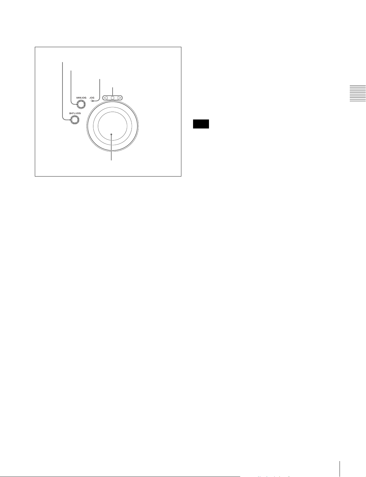
7 Shuttle/jog/variable-speed playback
control section
1 SHTL/JOG button
2 VAR/JOG button
3 JOG indicator
4 Jog/shuttle direction
indicators
5 Shuttle/jog dial
a SHTL/JOG button
Press this button, turning it on, to perform shuttle or jog
playback with the shuttle/jog dial.
• In variable-speed mode, you can make fine adjustments
to the playback speed over the range from –2 to +2 times
normal speed, according to the angular position of the
dial. There is a detent at the center position, for still
image playback.
Regardless of the playback mode, you will normally press
the SHTL/JOG or VAR/JOG button before turning the
dial. But it is also possible to put the unit into shuttle, jog,
or variable-speed mode simply by turning the dial (by
setting setup menu item 101 SELECTION FOR SEARCH
DIAL ENABLE to “dial”).
Note
If you do set the above item to “dial”, then you should
return the shuttle/jog dial to the center position after
conducting shuttle or variable-speed playback. If you do
not return the dial to the center position, playback in
shuttle or variable-speed mode can start because of
vibrations during other operations.
Chapter 2 Names and Functions of Parts
b VAR/JOG button
Press this button, turning it on, to perform variable-speed
or jog playback with the shuttle/jog dial.
c JOG indicator
Lights in green when the shuttle/jog dial is in jog mode.
d Jog/shuttle direction indicators
These show the playback direction in jog, shuttle, or
variable-speed mode.
b (green): Lights during playback in the reverse direction.
B (green): Lights during playback in the forward
direction.
x (red): Lights during still image display.
e Shuttle/jog dial
The dial switches between shuttle/variable-speed mode
and jog mode each time that you press it all the way in.
Shuttle/variable-speed mode: The dial is in the raised
position.
Jog mode: The dial is in the depressed position (the JOG
indicator is lit).
Turn the dial to the right to play in the forward direction,
and turn it to the left to play in the reverse direction.
• In jog mode, the playback speed varies from –1 to +1
times normal speed, according to the rotation speed of
the dial. There are no detents.
• In shuttle mode, the playback speed varies in the range
±20 times normal speed, according to the angular
position of the dial. There is a detent at the center
position, for still image playback.
Front Panel
19
Page 20

Display screen
Basic operation screen
Chapter 2 Names and Functions of Parts
1 Function menu
2 Audio input display/audio level meters
3 System information
4 Media status display
5 Recording or playback format
6 Clip information
7 Recording or chase play display
8 Time data display area
9 Status display area
a Function menu
Use the PAGE/HOME button to display this menu, and to
switch between the pages (HOME, P1 to P5) of the menu.
Each page has one to six setting items. Press the
corresponding function button to change a setting.
For details, see “Basic Operations of the Function Menu”
(page 41).
b Audio input display/audio level meters
Displays information about audio.
A Input signal display
B Data indication
F Level bars
E Reference level
D Audio channel
C Monitor channel
A Input signal display: Displays the audio input signal.
.
Display Input signal
ANA-1 Analog audio signal Channel 1, 3, 5, 7
ANA-2 Channel 2, 4, 6, 8
AES/EBU AES/EBU format digital audio signal (flashes
when there is no input signal)
HD-SDI HD-SDI audio signal (flashes when there is
no input signal)
SD-SDI SD-SDI audio signal (flashes when there is
no input signal)
SG Test signal from the internal signal generator
DVB-ASI DVB-ASI TS signal (flashes when there is no
input signal)
When the video input signal is set to “DVB-
ASI”, A1 INPUT to A8 INPUT are
automatically set to “DVB-ASI”.
B Data indication: Appears when the input signals are
non-audio signals.
C Monitor channel: Displays the audio monitoring
channels set with MONITR L and MONITR R on the
HOME page of the function menu (see page 41).
D Audio channel: Displays the audio channels.
Also indicates preset or variable-speed mode by its
color (see page 16).
White: Preset mode
Green: Variable-speed mode
E Reference level: Displays the reference level for
recording as set in the maintenance menu.
F Level bars: Display the audio recording or playback
levels of channels 1 to 8. The OVER indicators light
when the audio level exceeds 0 dB.
20
Front Panel
Page 21
c System information
A Reference signal
SD-SDI: SD-SDI video input
SG: Test video signal from the internal signal
generator
DVB-ASI
1)
: DVB-ASI TS signal
B Video input display
A Reference signal: This displays the type of reference
signal to which this unit is synchronizing.
When there is no display, the unit is synchronizing to
1) When the maintenance menu item M22: OPTION SETTING >DVBASI is set to “ON” with the optional PDBK-202 being installed (see
page 92).
The video signal input is selected with V INPUT on
page P1 INPUT of the function menu (see page 42).
the internal reference signal.
INPUT: Input video
HD REF: HD-format reference signal
SD REF: SD-format reference signal
B Video input display: This displays the currently
Note
The display blinks when there is no video input signal,
and when the video input signal does not match the
system frequency of this unit.
selected video input signal.
HD-SDI: HD-SDI video input
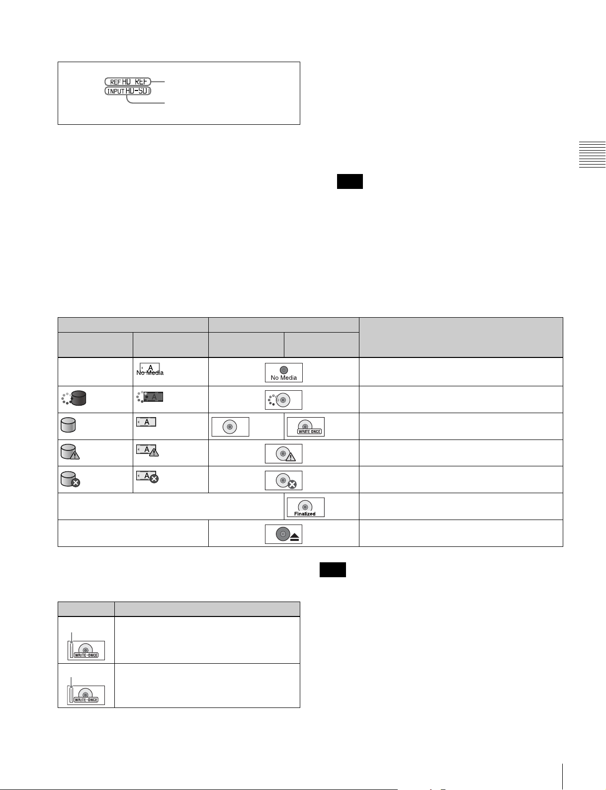
d Media status display
Displays the icons in the following table to indicate the
status of the selected recording media.
Icons Professional Disc Status
Internal storage Memory card
(slot A selected)
— Not loaded
PFD23A/
PFD50DLA
PFD128QLW
Chapter 2 Names and Functions of Parts
— Finalized
— Being ejected
The PFD128QLW media status display changes with the
remaining capacity of the recordable resource space (for
writing the disc management data, etc.).
Icon Status
Yellow bar
Red bar
The available recordable resource space is
running out.
There is no available recordable resource
space on the disc.
Note
The remaining capacity of recordable resource space is not
the same as the remaining recording capacity. When there
is no available recording resource space is left on the disc,
file writing may be disabled even with sufficient available
storage remaining.
e Recording or playback format
When the recording port is selected, displays the recording
format. When the playback port is selected, displays the
Being mounted
Normal status
Warning level error has occurred (finalizing is
impossible)
Error has occurred (restoring is impossible)
format of the clip being played.
Front Panel
21
Page 22
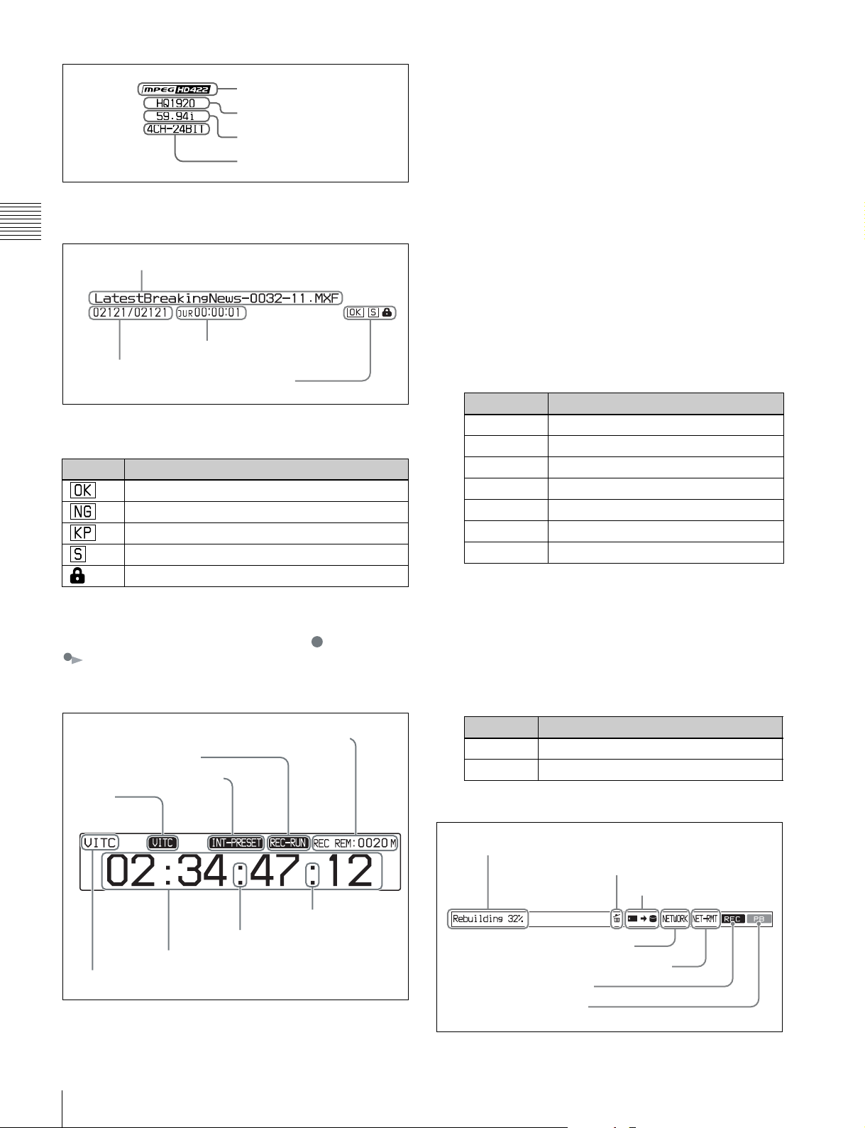
Codec
Video format
System frequency
Audio format
f Clip information
Displays clip information.
Chapter 2 Names and Functions of Parts
Clip name
Duration
Clip number/total number of clips
Property icons
During playback, the icons in the following table appear to
indicate the properties that have been set in a clip.
Icon Description
An OK flag is set
An NG flag is set
A KEEP flag is set
A shot mark is set
The clip is locked (protected)
g Recording or chase play display
When the recording media is the internal storage, an icon
appears to indicate the status of the unit ( : recording,
: chase play).
h Time data display area
A Remaining media capacity for recording or
playback: Displays the amount of remaining capacity
for recording or playback on the media.
B REC RUN/FREE RUN: Displays the timecode run
mode. The run mode is set with RUN MODE on page
P4 TC of the function menu (see page 43).
C Timecode generator mode: Displays the timecode
source and generation method (preset or regenerate).
These are set with TCG and PRST/RGN on page P4
TC of the function menu (see page 43).
D VITC: Lights in the following cases.
• When VITC is read in playback mode. (This has no
relations to the display in the time data display
area.)
• When VITC recording is possible.
E Time data type: Displays the type of time data
displayed in the time data display area. The type of
time data is selected with CNTR SEL on the HOME
page of the function menu (see page 41).
Display Type of time data
TC Timecode
COUNTER Elapsed recording/playback time
UB User bits
VITC VITC
VIUB VIUB
TCG Timecode generator value
UBG User bits generator value
F Time data: Normally displays timecode or VITC,
according to the selection made with TCR on page P4
TC of the function menu.
G DF/NDF indication: Displays the frame count mode
for the internal timecode reader (TCR) and internal
timecode generator (TCG). The frame count mode is
set with DF/NDF on page P4 TC of the function menu
(see page 43).
A Remaining media capacity for recording or playback
B REC RUN/FREE RUN
C Timecode generator mode
D VITC
G DF/NDF
indication
(TCR)
22
F Time data
E Time data type
Front Panel
G DF/NDF
indication
(TCG)
Display Frame count mode
. DF (drop-frame mode)
: NDF (non-drop-frame mode)
i Status display area
A Error, warning, and alarm messages
B Delete icon
C Copy icon
D Network connection display
E Network remote connection display
F Recording display
G Playback display
Page 23
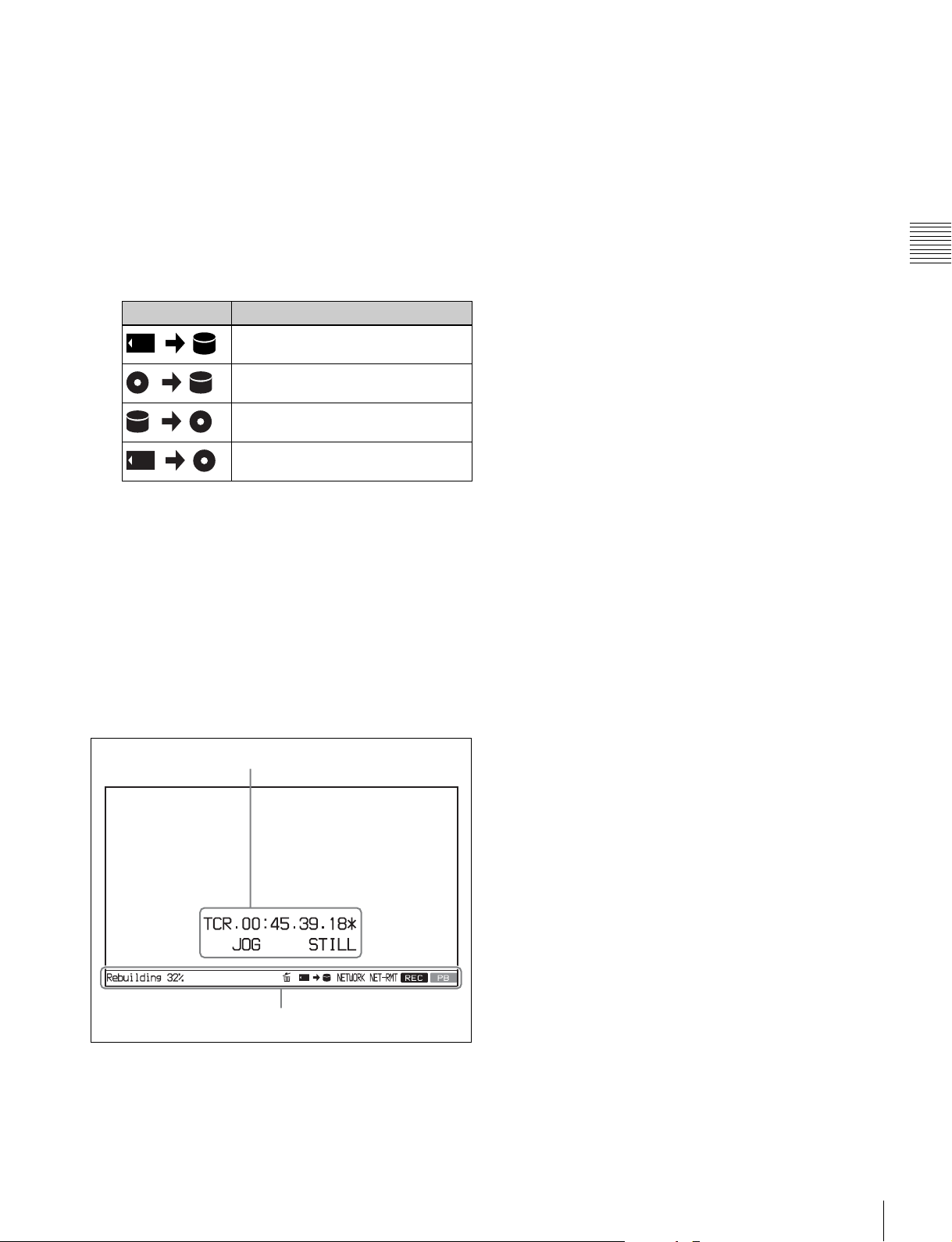
A Error, warning, and alarm messages: Messages
about operations and the status of the unit appear here.
The seriousness of the message is indicated by the
color, as follows.
Red: Error message (flashing)
Orange: Warning message
White: Alarm message
B Delete icon: Flashes while a clip deletion is being
executed.
C Copy icon: An icon representing the copy source and
copy destination light while a copy operation is being
executed between media.
Icon Description
Copy from memory card to internal
storage
Copy from Professional Disc to
internal storage
Copy from internal storage to
Professional Disc
Copy from memory card to
Professional Disc
D Network connection display: Lights while data is
being exchanged with a network connected external
device.
E Network remote connection display: Lights during a
network remote control connection to an external
device.
F Recording display: Lights when recording to the
internal storage is being performed.
G Playback display: Lights when a clip on the internal
storage or disc is in the open state.
Chapter 2 Names and Functions of Parts
Video monitor screen
A Superimposed information
B Status display area
A Superimposed information: Appears when CHAR
SEL on the HOME page of the function menu is set to
“ON”.
B Status display area: Displays messages and icons
about the status of the unit (see page 22).
Front Panel
23
Page 24
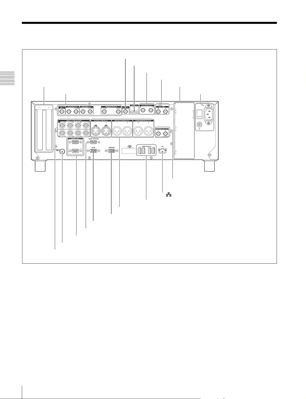
Rear Panel
Chapter 2 Names and Functions of Parts
1 PCIe expansion slot
1 HD/SD-SDI signal input/output
section (see page 25)
2 DVB-ASI OUTPUT connector
3 HDMI OUTPUT connector
4 REF. VIDEO INPUT connectors
2 Timecode input/output section (see page 26)
5 Redundant power supply unit installation section
3 Power supply section
(see page 26)
5 Analog audio signal input/output section (see page 27)
q; MONITOR connector
9 GPIO connector
8 VIDEO CONTROL connector
7 REMOTE (9P) 1, 2 connectors
6 SYSTEM TC INPUT connector
4 Digital audio signal input/output section (see page 27)
a PCIe expansion slot
For future expansion, this is provided to enable the
connection of units having a PCI Express interface.
b DVB-ASI OUTPUT (DVB-ASI output) connector
(BNC type)
This connector can output DVB-ASI TS signals when the
optional PDBK-202 MPEG TS Board is installed. For this,
it is necessary to set the maintenance menu item M22:
OPTION SETTING >DVB-ASI to “ON” (see page 92).
For details, see “About DVB-ASI Input/Output (When the
Optional PDBK-202 Is Used)” (page 111) for more
information about DVB-ASI TS signals.
qd COMPOSITE OUTPUT 1, 2 (MONITOR) connectors
qs (network) connector
qa MAINTENANCE connectors
c HDMI OUTPUT connector
Outputs digital signals (video, audio, control signals).
Output signals are E-E signals or playback signals,
according to the setting of the REC PORT and PB PORT
buttons on the front panel.
Allows you to connect a device with an HDMI input
connector, such as an HD projector or a high-definition
TV.
Audio output signals are the signals of the channels
selected with MONITR L and MONITR R on the HOME
page of the function menu.
d REF. VIDEO INPUT (reference video signal input)
connectors (BNC type)
The two connectors form a loop-through connection; when
a reference video signal is input to the left connector (IN),
24
Rear Panel
Page 25
the same signal is input from the right connector ( ) to
a connected device. When no connection is made to the
right connector, the left connector is automatically
terminated with an impedance of 75 ohms.
e Redundant power supply unit installation section
When using this unit in a system that requires high
reliability, you can back up the unit’s power supply by
installing the optional XDBK-101 Optional Power Supply.
This allows operation to continue even if one of the power
supply units fails.
To enable continuous operation after failure, set
maintenance menu item M22: OPTION SETTING
>REDUNDANT PSU to “ON”.
Note
The power supply and XDBK-101 do not support hot
swapping. Always turn the main power switch off before
exchanging the power supply or adding the XDBK-101.
f SYSTEM TC INPUT (system timecode input)
connector
If you want to input the standard reference timecode signal
of a broadcasting station as time data information, use this
connector to input it.
l (network) connector (RJ-45 type)
This is a 10BASE-T/100BASE-TX/1000BASE-T
connector for network connection.
CAUTION
• For safety, do not connect the connector for peripheral
device wiring that might have excessive voltage to this
port. Follow the instructions for this port.
• When you connect the network cable of the unit to
peripheral device, use a shielded-type cable to prevent
malfunction due to radiation noise.
m COMPOSITE OUTPUT (analog composite video
output) 1, 2 (MONITOR) connectors (BNC type)
Output analog composite video signals. Output signals of
the 2 (MONITOR) connector are E-E signals or playback
signals, according to the setting of the REC PORT and PB
PORT buttons on the front panel. You can superimpose
timecodes or error messages on the output of the 2
(MONITOR) connector when CHAR SEL on the HOME
page of the function menu is set to “ON”.
See “Basic Operations of the Function Menu” on page 41
for more information about the CHAR SEL setting.
Chapter 2 Names and Functions of Parts
g REMOTE (9P) (remote control 9-pin) 1, 2
connectors (D-sub 9-pin)
REMOTE (9P) 1 connector: Controls the recording port.
Connect a controller that supports the VDCP
protocol.
REMOTE (9P) 2 connector: Controls the playback port.
Connect a VTR or a controller that supports the
RS-422A Sony 9-pin VTR protocol (see page 32).
h VIDEO CONTROL connector (D-sub-9-pin)
Connect an HKDV-900 video control unit.
See page 114 for correspondence between setting items of
HKDV-900 and setup menu of this unit.
i GPIO (general-purpose I/O) connector
When you are using this unit in a larger system, such as a
playout system, this connector allows you to connect an
external device to control this unit’s playback, and to
return tally and alarm signals to the external device.
j MONITOR connector
Outputs the same video that appears on the display of this
unit’s front panel as analog RGB component video signals.
This connector is intended for connection to the VGA
input connector of a PC monitor.
k MAINTENANCE connectors
These are the USB connectors for maintenance.
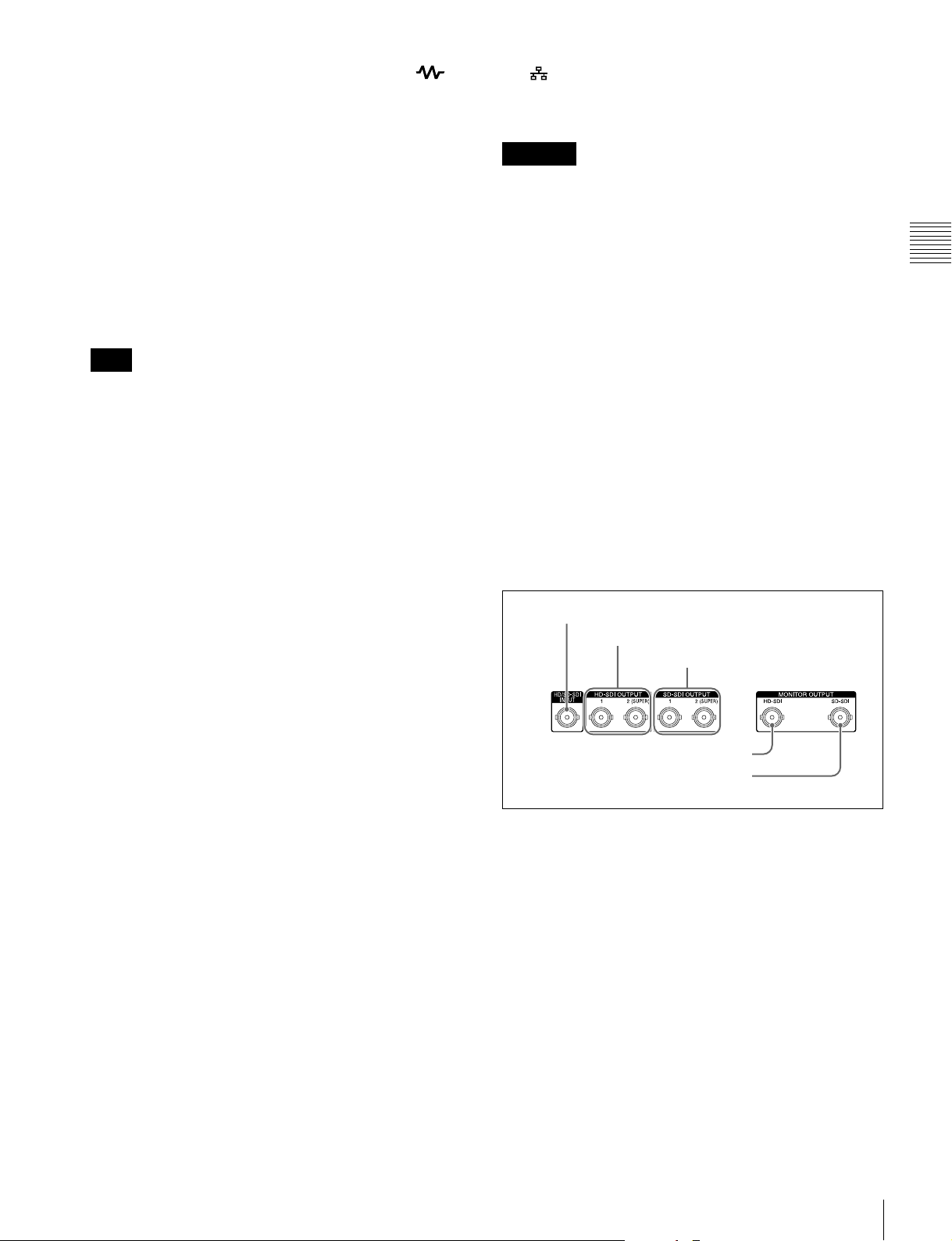
1 HD/SD-SDI signal input/output section
1 HD/SD-SDI INPUT connector
2 HD-SDI OUTPUT 1, 2 (SUPER) connectors
3 SD-SDI OUTPUT 1, 2
(SUPER) connectors
4 HD-SDI MONITOR OUTPUT connector
5 SD-SDI MONITOR OUTPUT connector
a HD/SD-SDI INPUT (HD-SDI/SD-SDI signal input)
connector (BNC type)
This inputs an HD-SDI or SD-SDI format video/audio
signal.
When the optional PDBK-202 MPEG TS Board is
installed, you can input DVB-ASI TS signals to this
connector. When inputting DVB-ASI TS signals, it is
necessary to set the maintenance menu item M22:
OPTION SETTING >DVB-ASI to “ON” (see page 92),
and set V INPUT to “DVB-ASI” on page P1 INPUT of the
function menu (see page 42).
For details, see “About DVB-ASI Input/Output (When the
Optional PDBK-202 Is Used)” (page 111) for more
information about DVB-ASI TS signals.
Rear Panel
25
Page 26
b HD-SDI OUTPUT 1, 2 (SUPER) (HD-SDI signal
output 1, 2 (superimpose)) connectors (BNC type)
These output HD-SDI format video/audio playback
signals.
You can superimpose timecodes or error messages on the
output of the 2 (SUPER) connector with the setting for
CHAR SEL on the HOME page of the function menu and
with the setting for setup menu item 028 HD
CHARACTER. You can always disable to superimpose
the data independent of the setting for CHAR SEL with the
setting for setup menu item 028.
Chapter 2 Names and Functions of Parts
See “Basic Operations of the Function Menu” (page 41)
for more information about the CHAR SEL settings.
See page 76 for more information about the setup menu
item 028 HD CHARACTER.
To treat the input and output signals of these connectors as
non-audio signals, set the maintenance menu item M37:
AUDIO CONFIG >M372: NON-AUDIO INPUT
(recording) (see page 93).
c SD-SDI OUTPUT 1, 2 (SUPER) (SD-SDI signal
output 1, 2 (superimpose)) connectors (BNC type)
These output SD-SDI format video/audio playback
signals.
When the unit is shipped from the factory, audio signal
output is eight channels with no switching, and RP188
timecode output is set to on. You can change these settings
with setup menu item 828 SDI AUDIO OUTPUT
SELECT and setup menu item 920 SD-SDI H-ANC
CONTROL (see page 86).
You can superimpose timecodes or error messages on the
output of the 2 (SUPER) connector with the setting for
CHAR SEL on the HOME page of the function menu and
with the setting for setup menu item 027 SD
CHARACTER. You can always disable to superimpose
the data independent of the setting for CHAR SEL with the
setting for setup menu item 027.
e SD-SDI (SD-SDI signal) MONITOR OUTPUT
connector (BNC type)
This outputs SD-SDI format video/audio signals. Output
signals are E-E signals or playback signals, according to
the setting of the REC PORT and PB PORT buttons on the
front panel.
Allows you to connect an SD monitor with an SD-SDI
input connector.
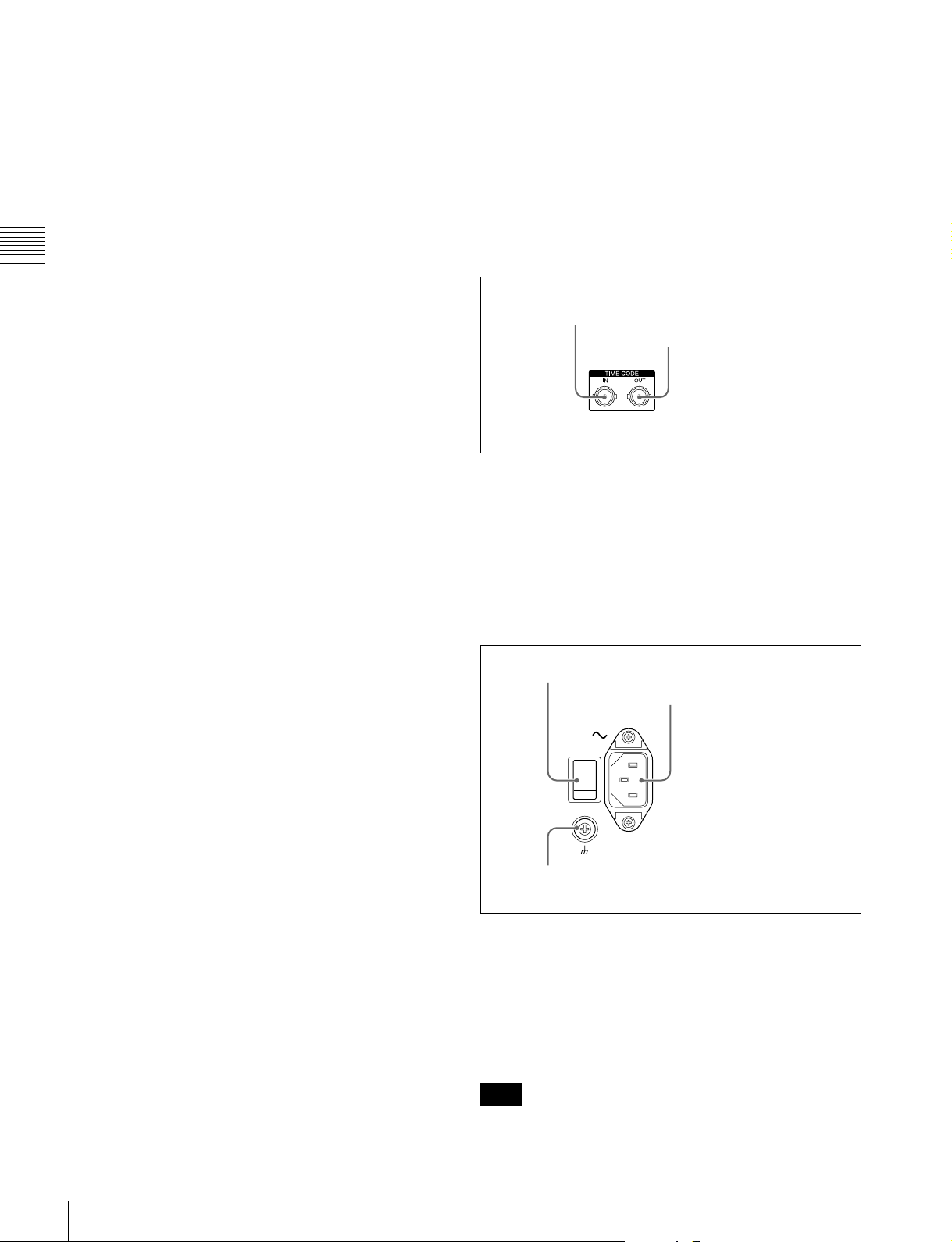
2 Timecode input/output section
1 TIME CODE IN connector
2 TIME CODE OUT
connector
a TIME CODE IN connector (BNC type)
This inputs an SMPTE timecode signal generated by an
external device.
b TIME CODE OUT connector (BNC type)
This outputs playback timecode signal.
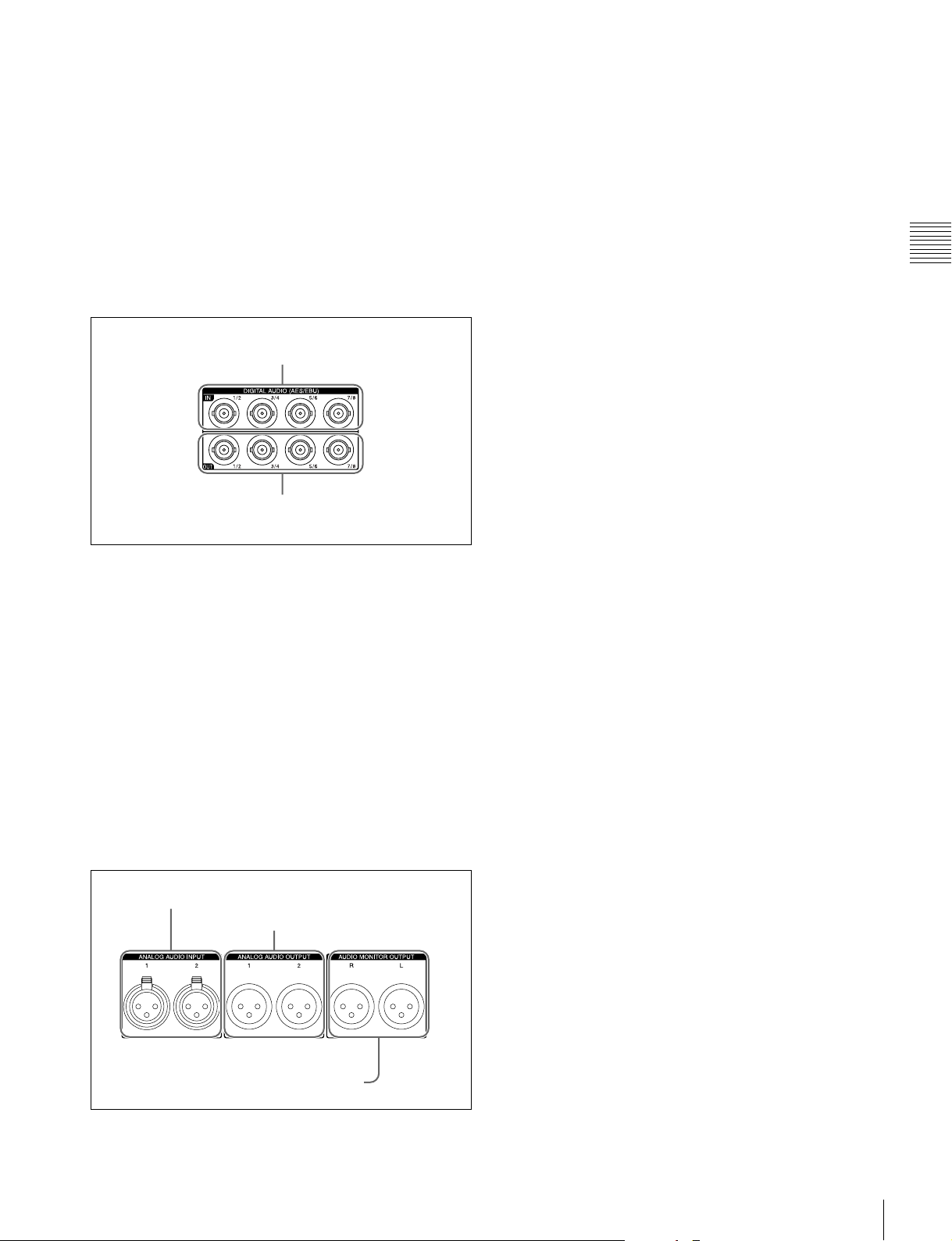
3 Power supply section
1 Main power switch
2 AC power input connector
See “Basic Operations of the Function Menu” (page 41)
for more information about the CHAR SEL settings.
See page 76 for more information about the setup menu
item 027 SD CHARACTER.
d HD-SDI (HD-SDI signal) MONITOR OUTPUT
connector (BNC type)
This outputs HD-SDI format video/audio signals. Output
signals are E-E signals or playback signals, according to
the setting of the REC PORT and PB PORT buttons on the
front panel.
Allows you to connect an HD monitor with an HD-SDI
input connector.
26
Rear Panel
3 Ground terminal
a Main power switch
Press the upper side to power the unit on. Press the lower
side to power the unit off.
When using the unit, normally leave the main power
switch in the on position, and use the on/standby button on
the front panel to switch the unit between the operating
state and standby state.
Note
Before turning the main power off, always check to be sure
that the on/standby indicator on the front panel is lit in red
Page 27
(showing that this unit is in the standby state), and then
press the main power switch to the off side.
b AC power input connector (-)
Connect to an AC power supply with the power cord (not
supplied).
c Ground terminal (U)
Connect this to ground as required.
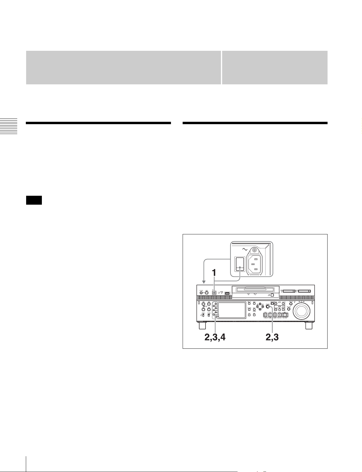
4 Digital audio signal input/output
section
1 DIGITAL AUDIO (AES/EBU) IN 1/2, 3/4, 5/6,
7/8 connectors
2 DIGITAL AUDIO (AES/EBU) OUT 1/2, 3/4, 5/6,
7/8 connectors
a ANALOG AUDIO INPUT 1, 2 connectors (XLR 3-
pin, female)
These input analog audio signals.
With A1 INPUT to A4 INPUT on page P1 INPUT (see
page 42) and A5 INPUT to A8 INPUT on page P2 INPUT
of the function menu, you can assign the signal input to
connector 1 to an odd numbered channel (1, 3, 5 or 7), and
assign the signal input to connector 2 to an even numbered
channel (2, 4, 6 or 8).
You can set the reference input level with the maintenance
menu item M37: AUDIO CONFIG (see page 93). (Factory
default setting: +4 dB)
b ANALOG AUDIO OUTPUT 1, 2 connectors (XLR
3-pin, male)
These output analog audio signals.
When the unit is shipped from the factory, the connector 1
is set to audio channel 1, and the connector 2 is set to audio
channel 2. You can change these settings with setup menu
item 824 ANALOG LINE OUTPUT SELECT (see
page 86).
You can set the output level with the maintenance menu
item M37: AUDIO CONFIG (see page 93). (Factory
default setting: +4 dB)
Non-audio signals are muted.
Chapter 2 Names and Functions of Parts
a DIGITAL AUDIO (AES/EBU) IN (digital audio
input) 1/2, 3/4, 5/6, 7/8 connectors (BNC type)
These input AES/EBU format digital audio signals.
b DIGITAL AUDIO (AES/EBU) OUT (digital audio
output) 1/2, 3/4, 5/6, 7/8 connectors (BNC type)
These output AES/EBU format digital audio signals.
To treat the input and output signals of these connectors as
non-audio signals, set the maintenance menu item M37:
AUDIO CONFIG >M372: NON-AUDIO INPUT
(recording) (see page 93).
5 Analog audio signal input/output
section
1 ANALOG AUDIO INPUT 1, 2 connectors
2 ANALOG AUDIO OUTPUT 1, 2
connectors
c AUDIO MONITOR OUTPUT R, L connectors
(XLR 3-pin, male)
Output audio signals for monitoring.
The monitored channel is selected with MONITR L and
MONITR R on the HOME page of the function menu.
Output signals are E-E signals or playback signals,
according to the setting of the REC PORT and PB PORT
buttons on the front panel.
See “Basic Operations of the Function Menu” (page 41)
for more information about the MONITR L and MONITR
R settings.
3 AUDIO MONITOR OUTPUT R, L connectors
Rear Panel
27
Page 28
Preparations
Chapter 3 Preparations
Supplying Power
Chapter
Initial Setup
3
Connect the AC power input connector to an AC power
source using the specified AC power cord. To supply
power, set the main power switch on the rear panel to on,
and then press the on/standby (1) button on the front panel
and hold it down for a short time (0.25 seconds or longer).
Note
To switch the state of this unit from standby state (the main
switch on the rear panel is on) to operative state, wait at
least three seconds after the unit has entered standby state
and then press the on/standby button on the front panel.
This unit is shipped with the area of use, system frequency,
and current date and time still unset.
Therefore, you need to make initial setup settings before
using the unit. (You cannot use the unit without setting it
up.)
Once the unit has been set up, the settings are retained even
when the unit is powered off.
To set the area of use and system
frequency
28
Supplying Power / Initial Setup
1
Power the unit on.
The INITIAL SETUP screen appears on the display.
Page 29
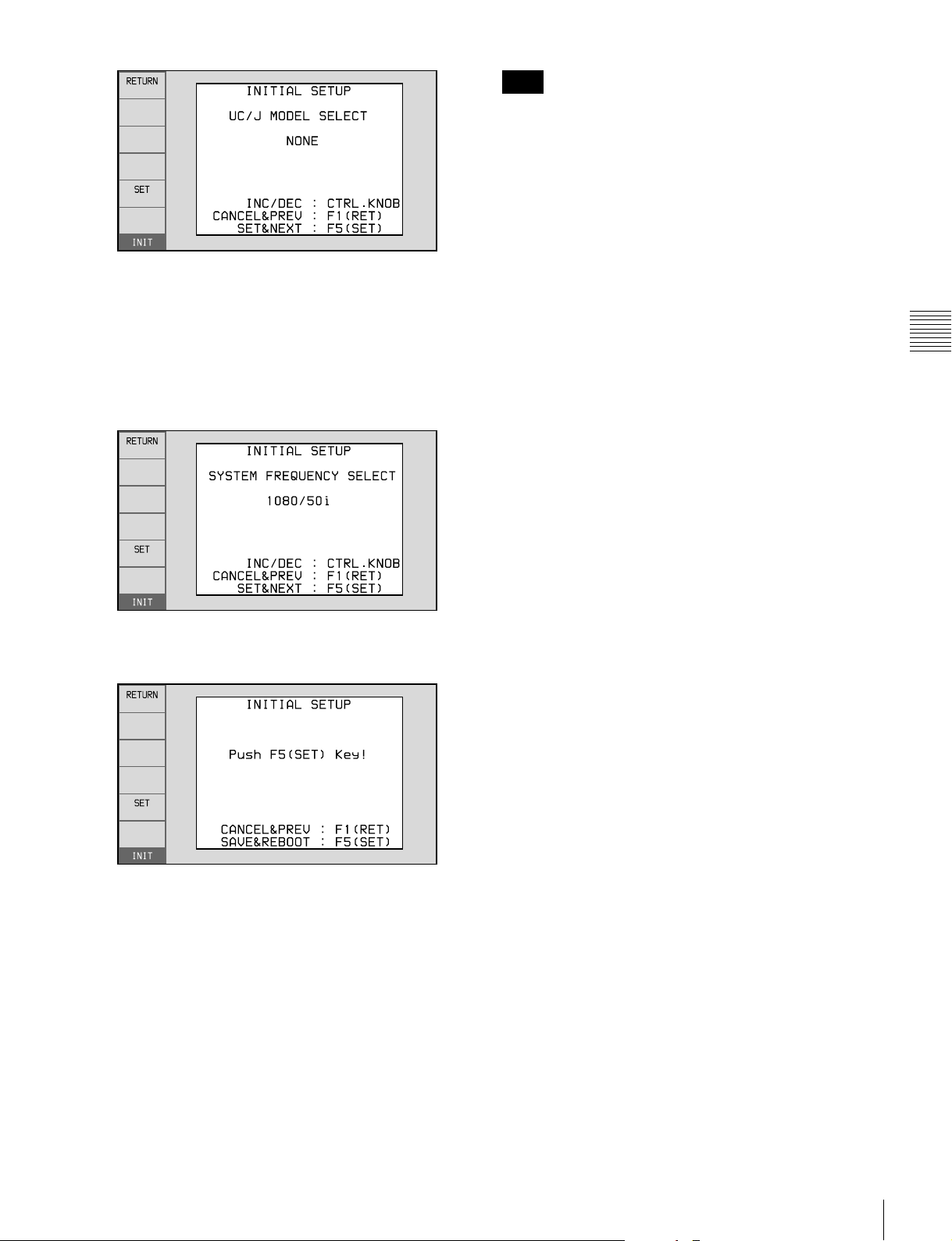
2
Turn the PUSH SET knob to select the area of use.
Display UC (for regions outside Japan) or J (for
Japan), and then press the SET function button (F5).
The system frequency screen appears.
3
Turn the PUSH SET knob to select the system
frequency.
Note
The time zone is reset to the factory default when you
execute the maintenance menu item M49: RESET ALL
SETUP. You will need to set it again. The date and time
are not reset.
Chapter 3 Preparations
4
Display the system frequency that you want to use, and
then press the SET function button (F5).
The message “NOW SAVING...” appears, and the
setting screen disappears. Then the unit powers itself
off and on again.
To return to the original screen without saving
settings
Press the RETURN function button (F1).
To set the date and time
Use the maintenance menu item M3D: DATE/TIME
PRESET.
See page 96 for more information about maintenance
menu operations.
Initial Setup
29
Page 30
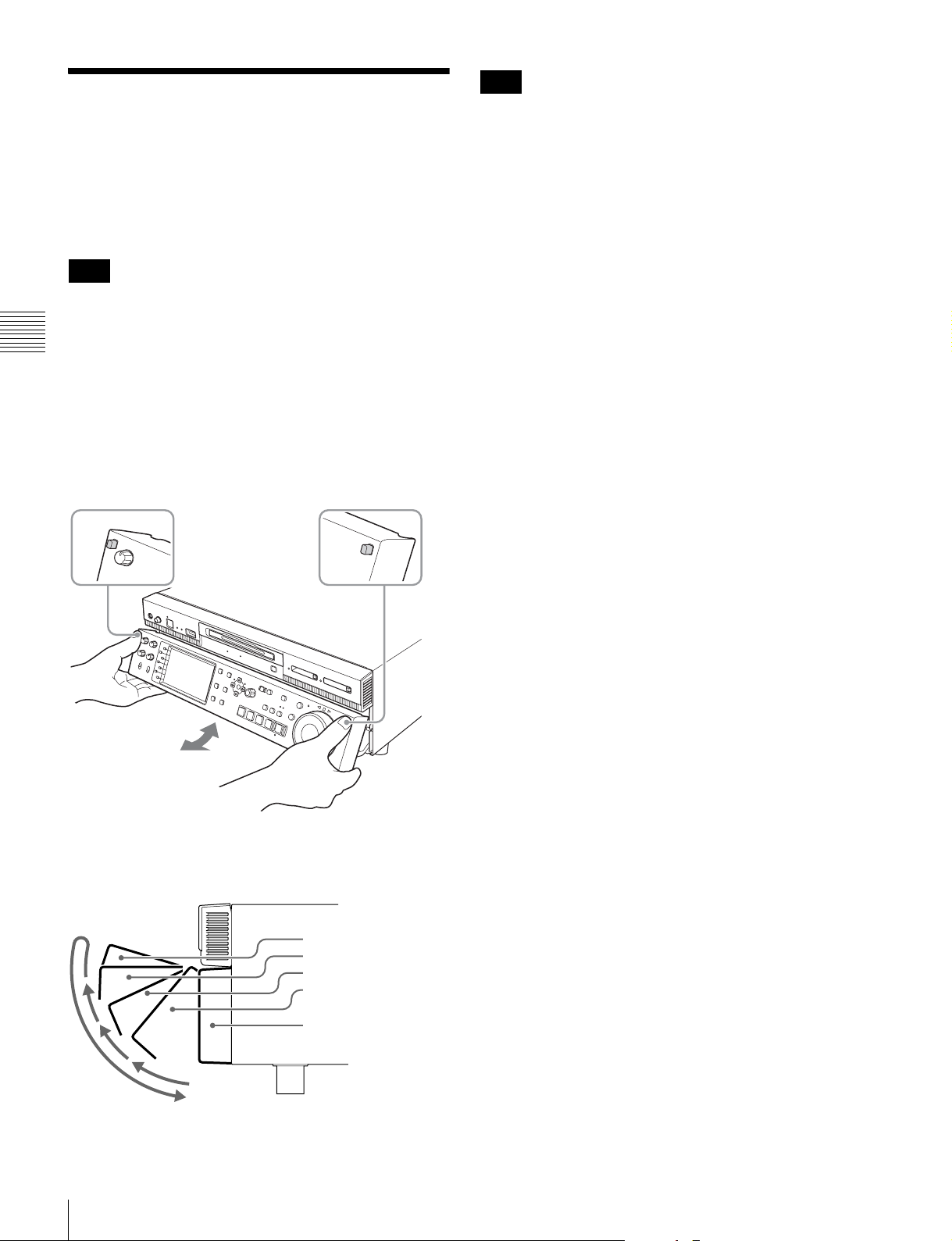
Front Panel Tilt Mechanism
The front panel of this unit has a tilt mechanism that allows
you to pull the front panel out and adjust it to a convenient
angle.
Note
Do not adjust the tilt during recording, playback, or
copying. Shocks or vibrations can affect the internal
storage, preventing normal recording, playback, or
Chapter 3 Preparations
copying.
Before adjusting the tilt, be sure to put the unit into stop
mode.
To pull the front panel out
Press and hold in the lock release buttons on both sides of
the front panel, and pull in the direction of the arrow.
Note
The angle cannot be fixed if you pull the front panel past
position 3 all the way out to the return position. To fix the
front panel, return it to position 0 and then pull it out to the
desired angle.
To return the front panel to its original
position
Unlock the front panel by pulling it out to the return
position. You can then return it to position 0.
To change the angle of the front panel
To change to a larger angle, pull the panel up to that angle.
To change to a smaller angle, pull the front panel all the
way up to the return position, releasing the lock. Then
return it to position 0 and pull it out again to the desired
angle.
You can fix the angle of the front panel in position 1 (40
degrees), position 2 (65 degrees), or position 3 (90
degrees).
Return position
Position 3 (90 degrees)
Position 2 (65 degrees)
Position 1 (40 degrees)
Position 0
30
Front Panel Tilt Mechanism
Page 31

Connections and
Connecting three of this unit to a laptop
computer via a LAN
Settings
Note
Production of some of the peripherals and related devices
described in this chapter may have been discontinued.
For advice about choosing devices, contact your Sony
sales representative.
Connections for using XDCAM Browser or a nonlinear editor that is not a Sony product
When using XDCAM Browser, you can have a remote
access to this unit from a network connected computer.
You can also access to this unit from a nonlinear editor that
is not a Sony product via FTP/CIFS, and use this unit as a
material server.
For an overview and installation of the XDCAM Browser,
access the Sony website closest to your area.
This unit
Laptop computer
Network cable
(not supplied)
To (network) connector
Chapter 3 Preparations
When using the (network) connector
The following shows connection examples.
Note
The XDS-PD1000 IP address and other network-related
settings are required for connections.
For details of the network-related settings, see “To change
network settings” (page 96).
Connecting this unit directly to a laptop computer
This unit
Laptop computer
To (network)
connector
Network cable (not supplied)
Connections and Settings
31
Page 32
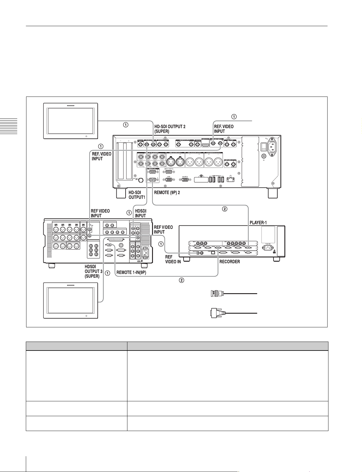
Connections for cut editing
The following figure shows a cut editing system
comprising this unit as a player.
When using an BVE-700/700A editing control unit
The following figure shows a cut editing system
comprising this unit as a player, an HDW-M2000/M2000P
To HD-SDI input connector
Chapter 3 Preparations
HD video monitor
HDW-M2000/M2000P
(recorder)
When making the connections, also refer to the manuals
provided with the equipment to be connected.
unit as a recorder, and a BVE-700/700A as an editing
control unit.
Reference video signal
This unit (player)
BVE-700/700A
(editing control unit)
1: 75 Ω coaxial cable (not supplied)
To HD-SDI input
connector
HD video monitor
2: 9-pin remote control cable (not supplied)
Settings on each unit
Device Settings
HDW-M2000/M2000P (recorder) • REMOTE 1 (9P) button: Lit
BVE-700/700A (editing control unit) • SYNCHRONIZE menu: OFF
This unit (player) • Setup menu item 208 PROTOCOL FOR REMOTE(9P): VTR
• REF.VIDEO INPUT connector 75 Ω termination switch: OFF
• Audio selection function switching button
INPUT button: HDSDI
• Function menu HOME >F1 (VID. IN): SDI
• Function menu page 1 >F1 (TCG): INT
• Function menu page 1 >F2 (PR/RGN): PRESET
• Function menu page 1 >F3 (RUN): FREE
• VTR constants (see below)
• REMOTE button (for playback port): Lit
32
Connections and Settings
Page 33
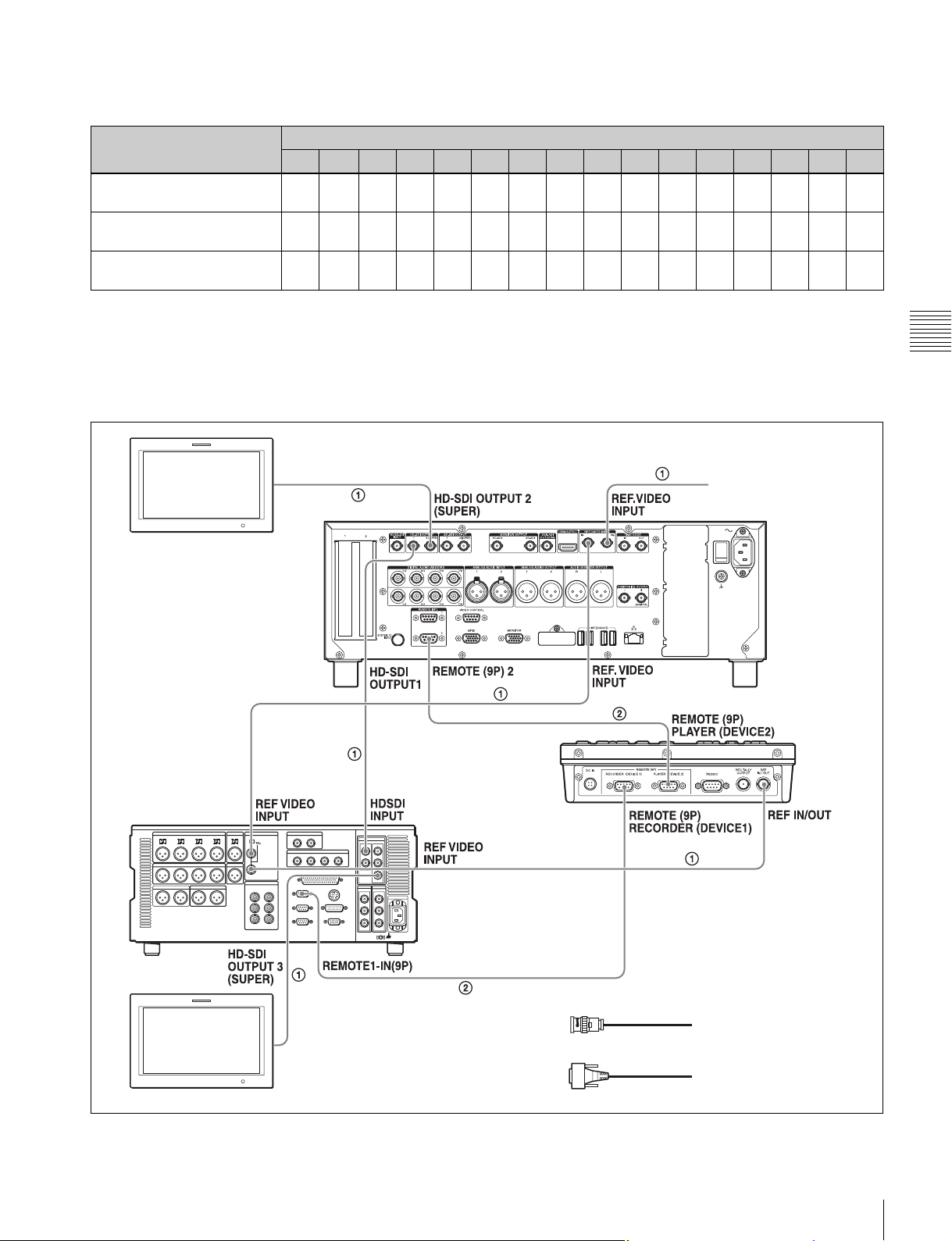
Setting of VTR constants
When connecting an editing control unit (BVE-700/700A/
2000) to use with this unit, set VTR constants as follows.
System frequency VTR constant
1 2 3 4 5 6 7 8 9 10 11 12 13 14 15 16
59.94i/59.94P/29.97P A0 B1
50i/50P/25P A1 B1
23.98P A2 B1
a) XDS-PD1000: B1, XDS-PD2000: B2
00 96 07 07 03 80 0A 07 FE 00 80 5A FF 5A
a)
B2
00 7D 07 07 03 80 0A 07 FE 00 80 4C FF 4B
a)
B2
00 78 07 07 03 80 0A 07 FE 00 80 48 FF 48
a)
B2
Using the RM-280 Editing Controller
The following figure shows a cut editing system
comprising this unit as a player, an HDW-M2000/M2000P
To HD-SDI input connector
HD video monitor
HDW-M2000/M2000P
(recorder)
Chapter 3 Preparations
unit as a recorder, and an RM-280 as an editing control
unit.
Reference video signal
This unit (player)
RM-280
(editing
controller)
HD video monitor
To HD-SDI input
connector
1: 75 Ω coaxial cable (not supplied)
2: 9-pin remote control cable (not supplied)
Connections and Settings
33
Page 34

Settings on each unit
Device Settings
HDW-M2000/M2000P (recorder) • REMOTE 1 (9P) button: Lit
RM-280 (editing controller) • EDITOR/REMOTE CONTROL selector switch: EDITOR
Chapter 3 Preparations
This unit (player) • Setup menu item 208 PROTOCOL FOR REMOTE(9P): VTR
• REF.VIDEO INPUT connector 75 Ω termination switch: OFF
• Audio selection function switching button
INPUT button: HDSDI
• Function menu HOME >F1 (VID. IN): SDI
• Function menu page 1 >F1 (TCG): INT
• Function menu page 1 >F2 (PR/RGN): PRESET
• Function menu page 1 >F3 (RUN): FREE
• Setup menu 01 PREROLL: 5s
• Setup menu 05 SYNC SEL: ON
• Setup menu 06 SYNC VTR: RECORDER
• Setup menu 09 EDIT DLY: AUTO
• Setup menu 10 R ST DLY: AUTO
• Setup menu 11 P ST DLY: AUTO
• Setup menu 19 FNC MODE: NORMAL
• REMOTE button (for playback port): Lit
Using the editing functions of the recorder (controlling through REMOTE (9P) connector)
The following figure shows a cut editing system
comprising this unit as a player, and an HDW-M2000/
M2000P unit as a recorder. In this example, video and
audio signals are connected by HD-SDI, and control
signals are transferred via a REMOTE (9P) connector.
HD video monitor
HDW-M2000/
M2000P (recorder)
To HD-SDI input connector
To HD-SDI input
connector
Reference video signal
This unit (player)
1: 75 Ω coaxial cable (not supplied)
2: 9-pin remote control cable (not supplied)
34
Connections and Settings
HD video monitor
Page 35

Settings on each unit
Device Settings
HDW-M2000/M2000P (recorder) REMOTE 1 (9P) button: Unlit
This unit (player) • Setup menu item 208 PROTOCOL FOR REMOTE(9P): VTR
• REMOTE button (for playback port): Lit
For details of HDW-M2000/M2000P settings, refer to the
HDW-M2000/M2000P Operation Manual.
Chapter 3 Preparations
Connections and Settings
35
Page 36

Synchronization Reference Signals
The synchronization reference signal generator of this unit
synchronizes to a reference signal input to the REF.
VIDEO INPUT connector or to a video input signal.
External synchronization is as follows, depending on the
Input to HD/SD-SDI
INPUT connector
Yes Yes Synchronize to the signal input to
Yes No No external synchronization is
Chapter 3 Preparations
No Yes Synchronize to the signal input to
No No No external synchronization is made
a) Same as when INT SG on page P1 INPUT of the function menu is set to
“ON”.
Input to REF. VIDEO
a)
INPUT connector
Setting of OUT REF on the HOME page
REF INPUT
the REF. VIDEO INPUT connector
made
the REF. VIDEO INPUT connector
setting of OUT REF on the HOME page of the function
menu, and on the type of the selected input signal. Video
output signals are always synchronized to the internal
synchronization reference signal.
Synchronization reference signals when
you are recording, playing, or editing 720P
signals
When you are recording, playing, or editing 720P signals,
set OUT REF on the HOME page of the function menu to
“REF”, and synchronize the synchronization reference
signal generator of this unit to a reference signal input to
the REF. VIDEO INPUT connector. The following
reference signals can be used.
720/59.94P system: 1080/59.94i tri-level sync signal, 525
black burst signal
720/50P system: 1080/50i tri-level sync signal, 625 black
burst signal
Synchronize to the signal input to
the HD/SD-SDI INPUT connector
Synchronize to the signal input to
the HD/SD-SDI INPUT connector
No external synchronization is
made
When you directly interconnect video I/O connectors
between two of this unit or between this unit and the
XDS-1000 or PDW-F1600/HD1500/F800/700, you can
record and dub 720P signals even if you set OUT REF on
the HOME page of the function menu to “INPUT”.
36
Synchronization Reference Signals
Page 37

Setting System Frequency
This unit can record and play back video at the system
frequencies of 1080/59.94i, 50i, 29.97P, 25P, and 23.98P
or 720/59.94P and 50P.
To select the system frequency
1
Set setup menu item 013 SYSTEM FREQUENCY
SELECT MENU to “on” and press the PUSH SET
knob.
The system frequency selection screen appears.
2
Turn the PUSH SET knob to select the system
frequency to be used.
Setting Time Data
Setting timecode
There are the following four ways of recording timecode:
Internal Preset mode: This records the output of the
internal timecode generator, set beforehand to an
initial value. The following run modes can be
selected.
• Free Run: Timecode advances continually.
• Rec Run: Timecode advances only during
recording.
System TC (system timecode) mode: This records the
output of the internal timecode generator,
synchronized to a broadcast station reference
timecode signal input to the SYSTEM TC INPUT
connector.
External Regen (regenerate) mode: This records the
output of the internal timecode generator,
synchronized to an external timecode generator. As
the external input, the timecode signal input to any of
the following connectors can be selected.
• TIME CODE IN connector: LTC
• HD/SD-SDI INPUT connector: VITC and LTC
External Preset mode: This directly records the input of
an external timecode generator. As the external input,
the timecode signal input to the TIME CODE IN
connector can be selected.
Chapter 3 Preparations
3
Press the SAVE function button (F5).
The message “Turn off/on POWER!!” appears.
4
After pressing the on/standby button and hold it down
for one second or longer to the unit into the standby
state, power it on again.
To record timecode after setting an initial
value (Internal Preset)
Proceed as follows with the function menu. For setting the
timecode, set TCG on page P4 TC of the function menu to
“INT” and PRST/RGN to “PRESET”.
Time data display area
Function menu
Function buttons
Setting System Frequency / Setting Time Data
37
Page 38

Setting an initial timecode value
1
Press the CNTR SEL function button on the HOME
page of the function menu, and select TC.
2
Press the TCG SET function button (F3).
The first digit of the time data display starts flashing.
Chapter 3 Preparations
3
Press the T or t function button (F1 or F2) to select
a digit to be set.
The selected digit starts flashing.
4
Use the PUSH SET knob or – or + function button (F3
or F4) to set the value for the selected digit.
To set the next-most significant digit (10s place)
Turn the PUSH SET knob while holding down the
SHIFT button.
Repeat steps 3 and 4 to set all digits that should be set.
To record timecode synchronized to the
station’s reference time
On page P4 TC of the function menu, set TCG to “SYS”.
This selects recording of timecode synchronized to a
broadcast station reference timecode signal input to the
SYSTEM TC INPUT connector.
To record with the internal timecode
generator synchronized to external
timecode (External Regen)
Use this method to synchronize the timecode generators of
a number of recorders, to record the playback timecode of
external VTRs, or to record while maintaining
synchronization between the source video and timecode.
Use either of the following procedures according to the
type of external timecode.
Synchronizing with timecode input to the TIME
CODE IN connector
1
Connect the timecode output of an external device to
the TIME CODE IN connector, and input a reference
video signal to the REF. VIDEO INPUT connector.
2
Make the following settings on page P4 TC of the
function menu.
• Set TCG to “EXT”.
• Set PRST/RGN to “TC”.
Synchronizing with embedded LTC input to the
HD/SD-SDI INPUT connector
To set to 00:00:00:00
Press the RESET button.
5
Press the SET function button (F5).
If RUN MODE on page P4 TC is set to “FREE RUN”,
the timecode starts running.
To cancel a setting
Press the EXIT function button (F6). Any new settings to
that point are canceled, and the setting operation is
terminated.
Setting the timecode to the current time
1
Set RUN MODE on page P4 TC to “FREE RUN” and
DF/NDF to “DF” (in 59.94i/59.94P/29.97P mode
only).
2
Perform steps 1 to 4 of “Setting an initial timecode
value” to set the timecode to a time slightly ahead of
the current time.
3
Press the SET function button (F5) at the instant when
the current time matches the displayed timecode.
1
Input an HD-SDI signal containing embedded LTC to
the HD/SD-SDI INPUT connector, and a reference
video signal to the REF. VIDEO INPUT connector.
2
Make the following settings on page P4 TC of the
function menu.
• Set TCG to “SDI”.
• Set PRST/RGN to “TC”.
Executing either of these procedures starts the internal
timecode generator running in synchronization with the
external timecode generator.
Once the internal timecode generator is synchronized with
the external timecode generator, the internal timecode
generator continues to run even if the external timecode
generator connection is removed.
The timecode advance mode is set automatically to Free
Run. The frame count mode (for system frequency 59.94i/
59.94P/29.97P only) is set to the same mode as the external
timecode signal (drop-frame or non-drop-frame).
38
Setting Time Data
Page 39

To check the synchronization to the external
signal
Press the REC PORT button to select the recording port.
Check that the timecode value shown in the time data
display coincides with the external timecode value.
Superimposed Text Information
To record external timecode directly
(External Preset)
When you use this method, the internal timecode generator
advances without being affected by the external timecode.
To directly record timecode input to the TIME
CODE IN connector
Input the timecode output of an external device to the
TIME CODE IN connector, and make the following
settings on page P4 TC of the function menu.
• Set TCG to “EXT”.
• Set PRST/RGN to “PRESET”.
Setting user bits
You can record up to 8 hexadecimal digits of information
(date, time, event number, etc.).
Select UB by pressing the CNTR SEL function button (F2)
in step 1 of “Setting an initial timecode value” (page 38)
and carry out steps 2 to 5. Settings are made in
hexadecimal (0 to 9, A to F).
The video signal output from the following connectors on
this unit contains superimposed text information,
including timecode and alarm messages.
• HD-SDI OUTPUT 2 (SUPER) connector
• SD-SDI OUTPUT 2 (SUPER) connector
• HD-SDI MONITOR connector
• SD-SDI MONITOR connector
• COMPOSITE OUTPUT 2 (MONITOR) connector
Chapter 3 Preparations
Adjusting the text display
You can adjust the position and type of the superimposed
text using setup menu items 002, 003, and 005.
For details, see “Items in the basic menu” (page 75).
Information displayed
1 Type of time data
2 Timecode reader drop-frame mark
(for 59.94i/59.94P/29.97P mode only)
3 Timecode generator drop-
frame mark (for 59.94i/
59.94P/29.97P mode only)
Time data
6 Operation mode
5 Port
Note
4 VITC field mark
The display shown above corresponds to the factory
default settings of the unit. You can change the type of
information to be displayed in the lower line of the display
by changing the setting of setup menu item 005 DISPLAY
INFORMATION SELECT.
For details, see “Items in the basic menu” (page 75).
Superimposed Text Information
39
Page 40

a Type of time data
Display Meaning
CNT Counter data
TCR TC reader timecode
UBR TC reader user bits data
TCR. VITC reader timecode
UBR. VITC reader user bits data
TCG TC generator timecode
UBG TC generator user bits data
Note
If the time data or user bits data cannot be read correctly,
they will be displayed with an asterisk. For example,
Chapter 3 Preparations
“T*R”, “U*R”, “T*R.” or “U*R.”.
b Timecode reader drop-frame mark (for 59.94i/
59.94P/29.97P mode only)
“.”: Indicates drop-frame mode.
“:”: Indicates non-drop-frame mode.
c Timecode generator drop-frame mark (for 59.94i/
59.94P/29.97P mode only)
“.”: Indicates drop-frame mode (factory default setting).
“:”: Indicates non-drop-frame mode.
d VITC field mark
“ ” (blank): Fields 1 and 3 (for 59.94i/59.94P/29.97P/
23.98P mode) or fields 1, 3, 5 and 7 (for 50i/50P/25P
mode)
“*”: Fields 2 and 4 (for 59.94i/59.94P/29.97P/23.98P
mode) or fields 2, 4, 6 and 8 (for 50i/50P/25P mode)
Display Operation mode
Block A Block B
PREV xxx Cuing up to the first frame of the
current clip.
F.FWD Fast forward search
F.REV Fast reverse search
PLAY Playback mode (servo unlocked)
PLAY LOCK Playback mode (servo locked)
REC Record mode (servo unlocked)
REC LOCK Record mode (servo locked)
JOG STILL A still picture in jog mode
JOG FWD Jog mode in forward direction
JOG REV Jog mode in reverse direction
SHUTTLE STILL A still picture in shuttle mode
SHUTTLE (Speed) Shuttle mode
VAR STILL A still picture in variable-speed
mode
VAR (Speed) Variable-speed mode
TOP 0001/xxxx Cuing up to the first frame of the
first clip.
END xxxx/xxxx Cuing up to the last frame of the
last clip.
PREROLL Cuing up during thumbnail search
CLOSE A clip is not selected.
MEDIA OUT No media is loaded.
LOADING Disc is being loaded.
UNLOADING Disc is being unloaded.
STANDBY OFF Standby off mode
e Port
P1: Indicates when the playback port is selected.
R1: Indicates when the recording port is selected.
f Operation mode
The field is divided into two blocks as shown below.
• Block A displays the operation mode.
• Block B displays the servo lock status or playback speed.
AB
Display Operation mode
Block A Block B
STOP Stop mode
NEXT xxx Cuing up to the first frame of the
next clip.
40
Superimposed Text Information
Page 41
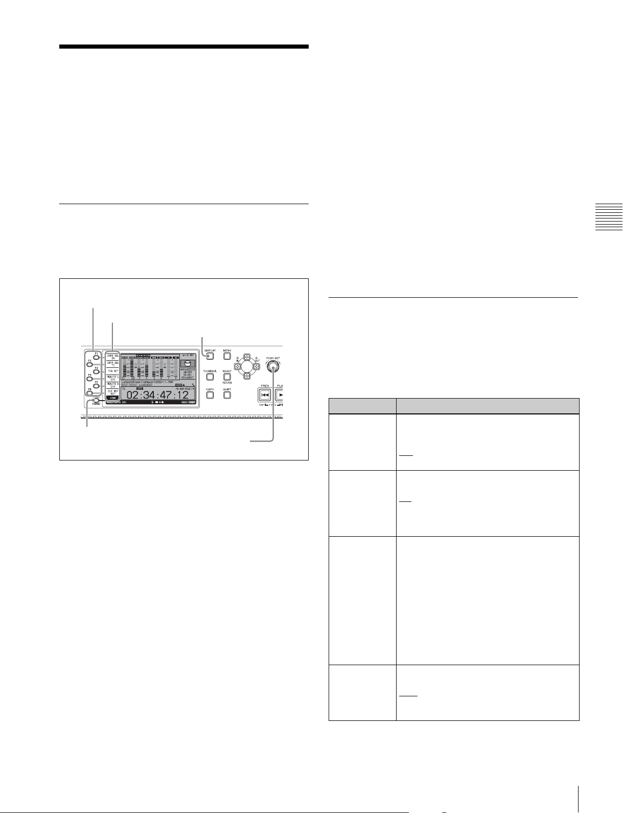
Basic Operations of the Function Menu
The function menu provides access to frequently used
settings, such as input video signal selection and timecode
settings.
Menu settings are stored in nonvolatile memory and are
preserved even after the unit is powered off.
Function menu operations
The function menu appears on the display of this unit.
The following figure shows the buttons (F1 to F6) used in
function menu operations.
To change the setting of a function menu
item
Use the function buttons.
To select the value of the setting item
Press the function button to the left of each setting item to
change the value of the item. Keep pressing the button
until the value you want appears.
To set the value of the setting item
• Press the function button to the left of each setting item
so that the setting value flashes to enable adjustment of
the value and then turn the PUSH SET knob to increase
or decrease the value.
• Turning the PUSH SET knob while holding down the
SHIFT button increases the increment of adjustment.
• Pressing the function button to the left of each setting
item while the setting value is flashing causes the value
to stop flashing and completes the adjustment.
Chapter 3 Preparations
Function buttons (F1 to F6)
Function menu
DISPLAY button
PAGE/HOME button
PUSH SET knob
To display the function menu
The function menu is made up of the HOME page and
pages P1 to P5.
If the function menu is not already visible, press the
PAGE/HOME button to display it. (The most recently
accessed function menu page appears.)
To display a different page
Each press of the PAGE/HOME button displays the next
function menu page in the order: HOME tP1 t P2 t
P3 t P4 t P5 t HOME…
• Turning the PUSH SET knob while holding down the
PAGE/HOME button changes the page forward or
backward.
• Pressing F1 to F5 buttons while holding down the
PAGE/HOME button switches the page directly to pages
P1 to P5.
To clear the function menu from the screen
Press the DISPLAY button to switch to the video monitor
screen.
Function menu settings
The following tables list the setting items on each page and
describe their setting values. Underlined values are the
factory defaults.
HOME page
Item Setting
F1: CHAR
SEL
F2: CNTR SEL Selects the type of time data to display in
F3: TCG SET/
UBG SET
F4: MONITR L Selects the channel to monitor as the left
Turns the display of character information
on the video monitor screen and on an
external monitor on and off.
: Character information on
ON
OFF: Character information off
the time data display area.
: Timecode
TC
COUNTER: Elapsed recording or playback
time
UB: User bits
• When CNTR SEL is set to “TC” or
“COUNTER”, the indication “TCG SET”
appears, and pressing the button displays
a screen where you can set the initial
value of timecode generated by the
internal timecode generator
page 38).
• When CNTR SEL is set to “UB”, the
indication “UBG SET” appears, and
pressing the button displays a screen
where you can set the user bits of
timecode
monitor channel.
CH1
CH1/2, CH3/4, CH5/6, CH7/8 (MIX)
a)
(see page 39).
, CH2, CH3, CH4, CH5, CH6, CH7,
CH8
a)
(see
Basic Operations of the Function Menu
41
Page 42

Item Setting
F5: MONITR R Selects the channel to monitor as the right
monitor channel.
CH1, CH2
, CH3, CH4, CH5, CH6, CH7,
CH8
CH1/2, CH3/4, CH5/6, CH7/8 (MIX)
F6: OUT REF Selects the reference signal for the output
signals of this unit.
: Use the signal input to the REF.
REF
VIDEO INPUT connector as the output
reference signal.
INPUT: Use the input video signal as the
output reference signal.
a) This is displayed only when TCG on page P4 TC of the function menu is
set to “INT”, and PRST/RGN is set to “PRESET”.
Chapter 3 Preparations
P1 INPUT page
Item Setting
F1: INT SG Set whether to select test signal from
internal signal generator.
: Do not select.
OFF
ON: Select.
F2: V INPUT Selects the video input signal.
: HD-SDI signal
HDSDI
SDSDI: SD-SDI signal
DVB-ASI: DVB-ASI TS signal
a)
Notes
• Test signal is input when INT SG on this
page is set to “ON” and setup menu item
710 is set to anything other than “off”.
• When the system frequency is 23.98P, the
setting is fixed “HDSDI”.
• When “DVB-ASI” is selected, the setting
for audio input signal is fixed to “DVBASI”.
F3: A1 INPUT Selects the audio input signal to assign to
audio channel 1.
: Audio signal embedded into SDI signal
SDI
ANALOG1: Input signal to the ANALOG
AUDIO INPUT 1 connector
AES/EBU1: Signal input to the DIGITAL
AUDIO (AES/EBU) IN 1/2 connectors
DVB-ASI: DVB-ASI TS signal
a)
Note
Test signals are input to all audio channels
1 to 8 when INT SG on this page is set to
“ON” and setup menu item 808 is set to
anything other than “off”.
F4: A2 INPUT Selects the audio input signal to assign to
audio channel 2.
: Audio signal embedded into SDI signal
SDI
ANALOG2: Input signal to the ANALOG
AUDIO INPUT 2 connector
AES/EBU2: Signal input to the DIGITAL
AUDIO (AES/EBU) IN 1/2 connectors
DVB-ASI: DVB-ASI TS signal
a)
Item Setting
F5: A3 INPUT Selects the audio input signal to assign to
audio channel 3.
: Audio signal embedded into SDI signal
SDI
ANALOG1: Input signal to the ANALOG
AUDIO INPUT 1 connector
AES/EBU3: Signal input to the DIGITAL
AUDIO (AES/EBU) IN 3/4 connectors
DVB-ASI: DVB-ASI TS signal
a)
F6: A4 INPUT Selects the audio input signal to assign to
audio channel 4.
SDI:
Audio signal embedded into SDI signal
ANALOG2: Input signal to the ANALOG
AUDIO INPUT 2 connector
AES/EBU4: Signal input to the DIGITAL
AUDIO (AES/EBU) IN 3/4 connectors
DVB-ASI: DVB-ASI TS signal
a) When the maintenance menu item M22: OPTION SETTING >DVB-ASI
is set to “ON” with the optional PDBK-202 being installed (see page 92).
a)
P2 INPUT page
Item Setting
F1: A5 INPUT Selects the audio input signal to assign to
F2: A6 INPUT Selects the audio input signal to assign to
F3: A7 INPUT Selects the audio input signal to assign to
F4: A8 INPUT Selects the audio input signal to assign to
F5: – (Unassigned function button)
F6: – (Unassigned function button)
a) When the maintenance menu item M22: Option Setting >DVB-ASI is set
to “ON” with the optional PDBK-202 being installed (see page 92).
audio channel 5.
: Audio signal embedded into SDI
SDI
signal
ANALOG1: Input signal to the ANALOG
AUDIO INPUT 1 connector
AES/EBU5: Signal input to the DIGITAL
AUDIO (AES/EBU) IN 5/6 connectors
DVB-ASI: DVB-ASI TS signal
a)
audio channel 6.
: Audio signal embedded into SDI
SDI
signal
ANALOG2: Input signal to the ANALOG
AUDIO INPUT 2 connector
AES/EBU6: Signal input to the DIGITAL
AUDIO (AES/EBU) IN 5/6 connectors
DVB-ASI: DVB-ASI TS signal
a)
audio channel 7.
: Audio signal embedded into SDI
SDI
signal
ANALOG1: Input signal to the ANALOG
AUDIO INPUT 1 connector
AES/EBU7: Signal input to the DIGITAL
AUDIO (AES/EBU) IN 7/8 connectors
DVB-ASI: DVB-ASI TS signal
a)
audio channel 8.
: Audio signal embedded into SDI
SDI
signal
ANALOG2: Input signal to the ANALOG
AUDIO INPUT 2 connector
AES/EBU8: Signal input to the DIGITAL
AUDIO (AES/EBU) IN 7/8 connectors
DVB-ASI: DVB-ASI TS signal
a)
42
Basic Operations of the Function Menu
Page 43

P3 AUDIO page
Item Setting
F1: A5 VOL Sets the volume of audio channel 5.
a)
The volume can be adjusted within the
range from –200 to 0
to +200 (–∞ to
+12 dB) by turning the PUSH SET knob.
The volume changes in steps of ±10 if you
hold the SHIFT button down while you turn
the knob.
F2: A6 VOL Sets the volume of audio channel 6.
a)
The volume can be adjusted within the
range from –200 to 0 to +200 (–∞ to
+12 dB) by turning the PUSH SET knob.
The volume changes in steps of ±10 if you
hold the SHIFT button down while you turn
the knob.
F3: A7 VOL Sets the volume of audio channel 7.
a)
The volume can be adjusted within the
range from –200 to 0 to +200 (–∞ to
+12 dB) by turning the PUSH SET knob.
The volume changes in steps of ±10 if you
hold the SHIFT button down while you turn
the knob.
F4: A8 VOL Sets the volume of audio channel 8.
a)
The volume can be adjusted within the
range from –200 to 0 to +200 (–∞ to
+12 dB) by turning the PUSH SET knob.
The volume changes in steps of ±10 if you
hold the SHIFT button down while you turn
the knob.
F5: – (Unassigned function button)
F6: – (Unassigned function button)
a) To enable this setting, the following settings are also required, in the same
way as for volume operations for channels 1 to 4.
• Set the VARIABLE switch of the front panel to “REC” or “PB”.
• Set setup menu item 131 AUDIO VOLUME to “each”.
P4 TC page
Item Setting
F2: PRST/RGN Selects the following for the internal
timecode generator.
PRESET
: Presets an initial value for the
timecode generated by the internal
timecode generator, as specified from
the front panel or remotely from the
device connected to a REMOTE (9P)
connector.
TC: Generate timecode synchronized to
timecode read by the internal
timecode reader.
VITC: Generate timecode synchronized to
VITC read by the internal timecode
reader.
F3: RUN
MODE
Selects the timecode run mode.
FREE RUN: Timecode advances as long
as the unit is powered on, regardless
of the unit’s operating state.
REC RUN
: Timecode advances only
during recording. When you select this
item, also set F1: TCG on this page to
“INT” and set F2: PRST/RGN to
“PRESET”.
F4: DF/NDF Selects the frame count mode for the
internal timecode generator and the
counter in 59.94i/59.94P/29.97P mode.
: Drop-frame mode
DF
NDF: Non-drop-frame mode
F5: PDPSET When the system frequency is set to 1080/
59.94i, 1080/29.97P, or 720/59.94P,
presets the timecode of the A frame of the
pulldown sequence.
24F TC: Reference timecode for A frame
30F TC: Timecode after pulldown
conversion from 24-frame timecode
F6: TCR Selects the type of timecode to display in
the time data display area.
: Display TC.
TC
VITC: Display VITC.
Chapter 3 Preparations
Item Setting
F1: TCG Selects the timecode signal to which the
internal timecode generator synchronizes.
: Follow the initial value set from the
INT
front panel or remotely from the
device connected to a REMOTE (9P)
connector.
EXT: Synchronize to external timecode
signal input to the TIME CODE IN
connector.
SYS: Synchronize to standard reference
timecode signal of a broadcasting
station input to the SYSTEM TC
INPUT connector.
SDI: Synchronize to timecode embedded
into HD-SDI or SD-SDI signal input to
the HD/SD-SDI INPUT connector.
Note
If you select “EXT” or “SDI” when a DVB-
ASI TS signal is input, the internal
timecode generator synchronizes to
timecode data contained in the TS signal.
P5 OTHER page
Item Setting
F1: INDEX Sets the index picture (thumbnail) of a clip
being played back. (see page 65)
Basic Operations of the Function Menu
43
Page 44

Handling Discs
Discs used for recording and playback
This unit can record and play back the following
Professional Disc
• PFD23A (capacity 23.3 GB)
• PFD50DLA (capacity 50.0 GB)
• PFD128QLW (capacity 128 GB)
1) Professional Disc is a trademark of Sony Corporation.
Chapter 3 Preparations
Notes
• It is not possible to use the following discs for recording
or playback:
- Blu-ray Disc
- Professional Disc for Data
• PFD128QLW is a quad-layer Write-Once Professional
Disc (hereafter referred to as “quad-layer WO disc”).
Pay due attention to the following points.
- Even if you delete any files written to the disc, no
available storage space will be increased.
- Reformatting the disc will not increase the available
storage space.
- Repetitive file writing will consume the recordable
resource space (for writing the disc management data,
etc.) on the disc. If no available recordable resource
space is left on the disc, file writing may be disabled
even with sufficient available storage space remaining.
- No file can be written after the disc is finalized.
• PFD128QLW discs can be used only by XDCAM
devices with the XL-QD mark (see the following
illustration). They cannot be used by XDCAM devices
without this mark.
1)
formats.
• Do not touch the surface of the disc itself within the
cartridge.
• Deliberately opening the shutter may cause damage.
• Do not disassemble the cartridge.
• The supplied adhesive labels are recommended for
indexing discs. Apply the label in the correct position.
Storage
• Do not store discs where they may be subjected to direct
sunlight, or in other places where the temperature or
humidity is high.
• Do not leave cartridges where dust may get inside.
• Store cartridges in their cases.
Care of the discs
• Remove dust and dirt on the outside of a cartridge using
a soft dry cloth.
• If condensation forms, allow ample time to dry before
use.
Write-protecting discs
To protect the content recorded on the disc from accidental
erasure, move the Write Inhibit tab on the lower surface of
the disc in the direction of the arrow, as shown in the
following figure.
Lower surface of the disc
Write Inhibit tab settings
Write Inhibit tab
Slide in the direction of the arrow
XL-QD mark
Notes on handling
Handling
The Professional Disc is housed in a cartridge, and is
designed to allow handling free of risk from dust or
fingerprints. However, if the cartridge is subjected to a
severe shock, for example by dropping it, this can result in
damage or scratching of the disc. If the disc is scratched, it
may be impossible to record video/audio, or to play back
the content recorded on the disc. The discs should be
handled and stored carefully.
44
Handling Discs
Recording enabled
Recording disabled
You can also write protect individual clips. For details, see
“Locking (write-protecting) clips” (page 64).
Loading and unloading a disc
When the on/standby button and indicator are lit green,
you can load and unload a disc as shown in the following
figure.
Page 45
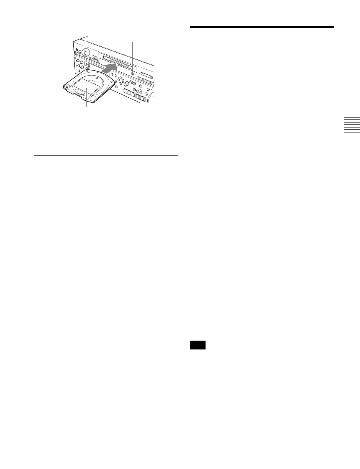
On/standby button and indicator
To load
Insert a disc face up.
The disc is drawn in.
To unload
Press the EJECT button.
Handling SxS Memory Cards
About SxS memory cards
SxS memory cards that can be used with
this unit
Use the following Sony SxS memory cards (SxS PRO or
SxS-1) with this unit.
When the EJECT button is pressed during recording,
recording stops and the disc is ejected.
Formatting a disc
Unused discs are formatted automatically when they are
loaded into this unit.
To format a recorded disc, use the Clip Menu (see
page 62).
SxS PRO
•SBP-8 (8 GB)
• SBP-16 (16 GB)
• SBP-32 (32 GB)
SxS-1
• SBS-32G1 (32 GB)
• SBS-64G1 (64 GB)
• SBS-32G1A (32 GB)
• SBS-64G1A (64 GB)
Proper operation cannot be guaranteed when memory
cards other than SxS PRO and SxS-1 are used.
The memory cards listed above comply with the
ExpressCard standard.
• SxS, SxS PRO and SxS-1 are trademarks of Sony
Corporation.
• The ExpressCard label and logo are property of the
Personal Computer Memory Card International
Association (PCMCIA) and are licensed to Sony
Corporation. Other trademarks and trade names are the
property of their respective owners.
Use of the following optional accessories allows you to use
“Memory Sticks” and SDHC cards on this unit.
• MEAD-MS01 Memory Stick Adapter (for “Memory
Stick PRO-HG Duo” HXA series)
• MEAD-SD01 SD Card Adapter (for SDHC cards)
Chapter 3 Preparations
Note
When you use a “Memory Stick” adapter or SD card
adapter, check to be sure that this unit is in operative state
before inserting the combined media and adapter.
SxS memory card operations supported by
this unit
• Thumbnail display
• Copying from memory cards to internal storage
Handling SxS Memory Cards
45
Page 46
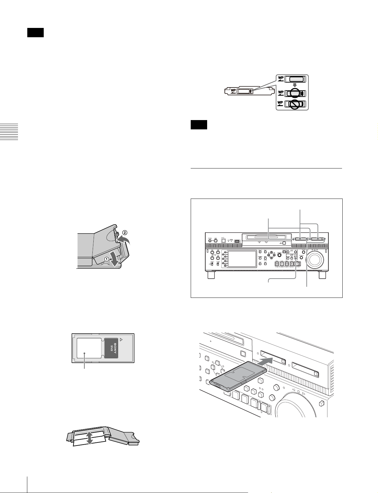
Note
Recording to SxS memory cards (including copying),
playback, clip deletion, formatting, and other operations
are not supported.
Notes on the use of SxS memory cards
• Recorded data may be lost or corrupted in the following
cases.
- When this unit is subjected to shock or vibrations
during reading or writing of an SxS memory card, and
when this unit is powered off or an SxS memory card
is removed during reading or writing
- When this unit is used in an environment subject to
Chapter 3 Preparations
static electricity or electric noise
• Do not use or store SxS memory cards in locations that
are:
- outside the specified environmental ranges
- very hot, such in as vehicles parked in the sun during
summer, or exposed to direct sunlight, or near heaters
- subject to high humidity and corrosion
• When inserting a memory card, insert with the label side
facing the correct direction.
• Carry and store SxS memory cards in their cases, and
lock the cases securely.
To prevent accidental erasure
You can prevent accidental recording, editing, and
deletion of data on an SxS memory card by setting the
write protect switch to the WP side.
Write protect switch
Note
Do not touch the write protect switch while an SxS
memory card is loaded in a memory card slot. Eject the
card before setting the write protect switch.
Inserting/removing an SxS memory card
Memory card slots
MEMORY ACCESS A/B lamps
• Guard against accidents and inadvertent data loss by
backing up the data stored on SxS memory cards. Sony
cannot be responsible for any consequences of damage
to or loss of data stored on SxS memory cards.
• Do not attach anything other than the supplied labels in
the designated label space. When attaching a label, make
sure it does not protrude beyond the label space.
SxS PRO 8GB
Label space
• Clip operations may not be possible when the remaining
capacity of the media is low. In this case, use a computer
to delete unneeded files and try again.
• Open the memory card case completely before storing a
card in the case or removing a card from the case.
MEMORY button
Eject buttons
To insert an SxS memory card
Insert the SxS memory card into the card slot.
Insert with
the label
side facing
upward
The lamp lights in red then changes to green once the
memory card is ready for use.
46
Handling SxS Memory Cards
Page 47
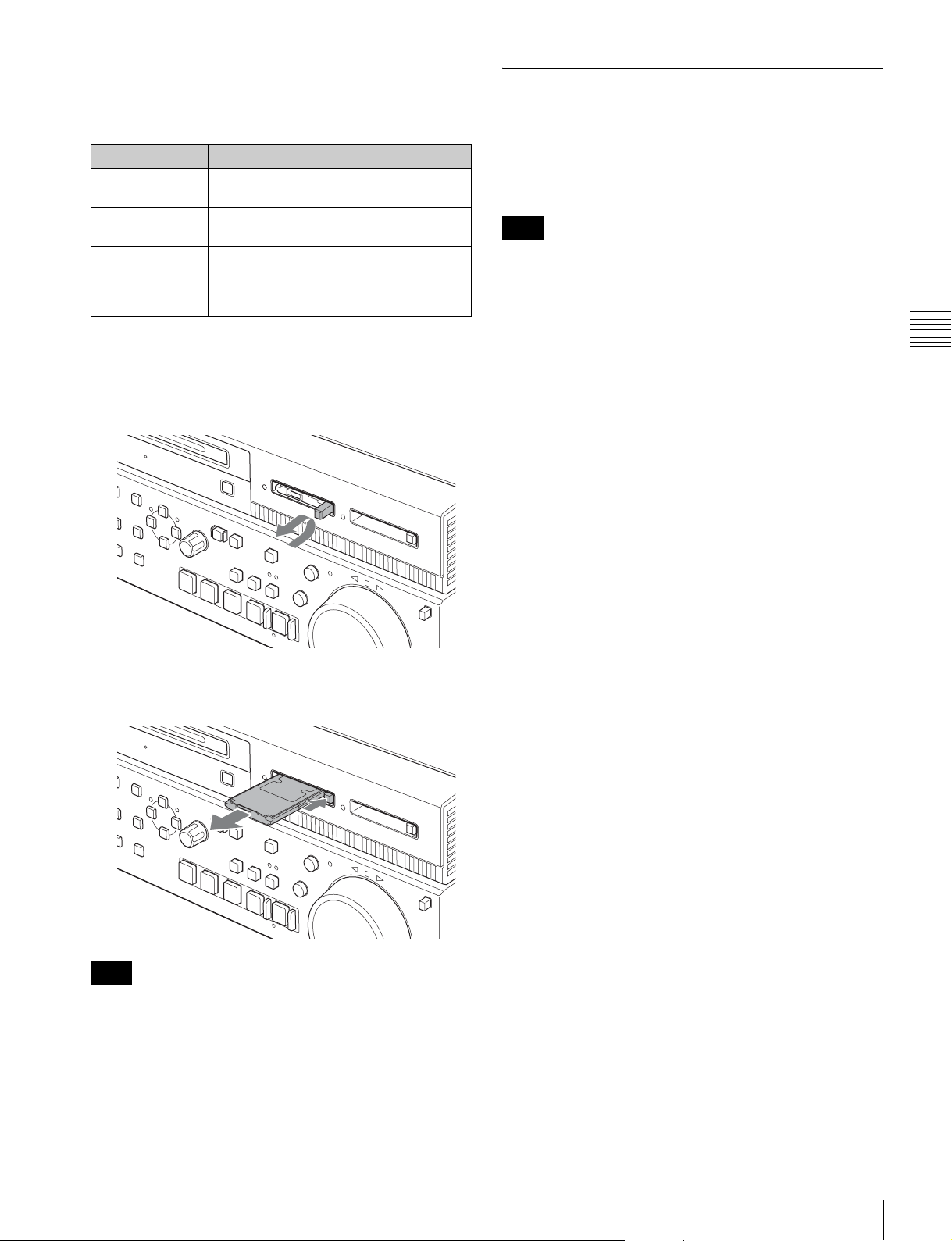
Status indications by the MEMORY ACCESS A/B
lamps
Card slots A and B are accompanied by the respective
lamps to indicate their statuses.
Lamp Slot statuses
Lights in orange Accessing the loaded SxS memory card
(writing/reading data)
Lights in green Standby (ready for recording or playback
using the loaded SxS memory card)
Off • No SxS memory card is loaded.
• The loaded card is invalid.
• An SxS memory card is loaded, but
another slot is selected.
Switching between SxS memory cards
When SxS memory cards are loaded in both memory card
slots A and B, press the MEMORY button to select the
card you wish to use.
Note
The MEMORY button is disabled while copying is in
progress, that is, switching is not executed even if you
press the button.
To remove an SxS memory card
1
Press the eject button to release the lock, then pull the
button out.
Press the button
once to release
the lock
2
Press the eject button again to remove the card.
Chapter 3 Preparations
Note
Data are not guaranteed if the power is turned off or a
memory card is removed while the card is being accessed.
All data on the card may be destroyed. Be sure that the
MEMORY ACCESS A/B lamps are lit in green or off
when you turn off the power or remove memory cards.
Handling SxS Memory Cards
47
Page 48

Recording, Playback and
Copying
Recording
This section describes video and audio recording on the
unit.
Chapter 4 Recording, Playback and Copying
See page 41 “Basic Operations of the Function Menu” for
more information.
See page 74 “Menus” for more information about setup
menu operations.
Preparations for recording
Make the following settings and adjustments before
starting to record.
Video input signal selection: Select with V INPUT on
page P1 INPUT of the function menu.
Audio input signal selection: Select with A1 INPUT to
A4 INPUT on page P1 INPUT and A5 INPUT to A8
INPUT on page P2 INPUT of the function menu.
Timecode and user bits settings: See “Setting timecode”
(page 37).
Selection of time data to display: Select with CNTR SEL
on HOME page of the function menu.
Selection of audio channels to monitor: Select with
MONITR R and MONITR L on the HOME page of
the function menu.
Volume adjustment of the monitor audio: Adjust with
the LEVEL adjustment knob.
Carrying out recording
You can record to the internal storage, or record to the
internal storage and a Professional Disc simultaneously.
One recording segment (from the start to the end of
recording) is called a “clip”.
When recording to the internal storage, the maximum
recording time for one clip is six hours.
Chapter
For the available recording time of each media, see
“Recording and playback time” under “Specifications”
(see page 108).
If the clip list screen is displayed, press the THUMBNAIL
button to switch to the basic operation screen or the video
monitor screen.
1
Press the REC PORT button.
2
Select the media.
For recording to the internal storage: Press the
INTERNAL button.
For simultaneous recording to both media: Press
the DISC button and the INTERNAL button
simultaneously.
3
Hold down the REC button, and press the PLAY
button.
Recording starts.
In the case of simultaneous recording, the
icon appears in the status display area.
(Simultaneous recording can be performed by
simultaneously executing recording to the internal
storage and copying from the internal storage to the
Professional Disc.)
4
To stop recording, press the STOP button.
This unit enters a stop mode.
4
48
Recording
Page 49

In the case of simultaneous recording, this unit enters
a stop mode after copy from the internal storage to the
Professional Disc.
• When recording to the internal storage becomes
impossible, the recording to the Professional Disc also
stops.
To stop only the recording to the Professional Disc
during simultaneous recording
Press the COPY button and then press the RESET
button to abort the copy operation.
For the behavior of media in simultaneous recording,
see “Behavior of media in simultaneous recording”
(see page 49)).
Notes
• The shortest clip that can be recorded is 2 seconds long.
Even if the time from the operation to start recording to
the operation to stop recording is less than two seconds,
the recording continues for two seconds.
• The maximum recordable number of clips depends on
the media, as follows.
Media Maximum recordable number
HDD 3000
SSD 3000
PFD23A 300
PFD50DLA 300
PFD128QLW 1200
When the maximum recordable number is reached, no
further recording is possible. (The message “MAX #
Clips” appears in the status display area.)
• This unit can record video input signals that are not
synchronized to a reference signal. However, in that
case, video breakup and audio noise may occur in E-E
playback.
• During recording, do not turn off the main power switch
on the rear panel or disconnect the power cord. This
could cause the clip being recorded to be lost.
Note that no recorded clip contents are lost when the
on/standby button on the front panel is set to standby
during recording, because the unit does not enter standby
mode until after the end of recording processing.
Behavior of media in simultaneous recording
• If the Professional Disc is in an unrecorable state,
pressing the REC button and PLAY button
simultaneously in step 3 displays a message, and
recording to the internal storage only starts.
• If during recording the remaining space of the
Professional Disc becomes insufficient, then the
recording to the disc stops. (The clip is established and
the disc is ejected.) The recording to the internal storage
continues.
• If during recording you press the EJECT button to
remove the Professional Disc, the recording to the disc
stops. (The clip is established and the disc is ejected.)
The recording to the internal storage continues.
To adjust the audio recording levels
When carrying out audio recording at a reference
level
Set the VARIABLE switch to “PRESET”.
The audio signals will be recorded at a preset reference
level.
You can change the reference level and the input levels
with maintenance menu item M37: AUDIO CONFIG.
See page 96 for more information about how to make
maintenance menu settings.
Manually adjusting the audio recording levels
Set the VARIABLE switch to “REC” and use the CH-1/
ALL CH and CH-2 to CH-4 knobs to adjust CH-1 to CH-4,
and use A5 VOL to A8 VOL on page P3 AUDIO of the
function menu to adjust CH-5 to CH-8 so that the audio
level indications on the audio level meters do not exceed
0 dB for a maximum volume.
Mixed recording of clips in different formats on the same disc
The recording format is regarded as different whenever the
system frequency, video resolution, video codec/bit rate,
or number of audio channels or number of bits does not
match.
Mixed recording of clips in different formats on
the internal storage
You can record clips to the internal storage at different
system frequencies and in different formats (HD422/
HD420).
Mixed recording of clips in different formats on
the Professional Disc
As long as the frame frequency group is the same, clips in
different recording formats can be recorded or written to
the same disc, for example HD422 and HD420SP clips, by
putting this unit into mixed format recording mode.
Frame frequency groups
The system frequencies supported by this unit are divided
into frame frequency groups, as shown in the following
table.
Frame frequency System frequency
59.94 Hz 59.94P
59.94i
29.97P
Chapter 4 Recording, Playback and Copying
Recording
49
Page 50

Frame frequency System frequency
50 Hz 50P
50i
25P
23.98 Hz 23.98P
Playback
This section describes playback of video and audio on the
unit.
Notes
• When the unit is in a mode that calls for playback across
clips that were recorded in different recording formats,
video and audio playback may stop at the point where
the format changes from one format into another, and
then start again.
• If a transition point between two clips with different
recording formats exists in the preroll segment, that
segment cannot be edited.
Chapter 4 Recording, Playback and Copying
Before starting playback, make the following settings and
adjustments.
Selection of time data to display: Select with CNTR SEL
on HOME page of the function menu.
Selection of audio channels to monitor: Select with
MONITR L and MONITR R on the HOME page of
the function menu.
Volume adjustment of the monitor audio: Adjust with
the LEVEL adjustment knob.
Playback target (when playing back clips/
EDLs on the internal storage)
Only the currently selected clip/EDL on the internal
storage is played back.
The available playback types include normal playback,
high-speed playback in the forward or reverse directions,
and jog, shuttle, and variable-speed playback. Playback
stops when it reaches the start or end of the clip/EDL. The
next and preceding clips are not played, even if they exist
on the media.
To move to another clip, press the PREV, NEXT, SHIFT
+ PREV, or SHIFT + NEXT button, or perform a
thumbnail search.
About the playback start position
Immediately after this unit starts
All clips are closed. To play a clip or an EDL, select it in a
clip list screen.
After disc insertion
The unit stops at the position of the disc when it was most
recently ejected.
Press the PLAY button to resume playback at the most
recent position.
The playback position is saved to the disc when the disc is
ejected, which allows playback to start at that position
whenever it is loaded into any XDCAM player.
Notes
• This function is not available when the Write Inhibit tab
of the disc is set to the recording disabled position.
When the Write Inhibit tab is in the recording enabled
position and the format of recorded sections on the disc
is not the same as the recording format setting of this
unit, the REC INHI indicator lights, but in this case the
playback position is saved to the disc.
• When playback is stopped on an EDL, the playback
position is not saved.
50
Playback
Page 51

• In the case of quad-layer WO discs, the playback
position is not saved.
After recording
The unit stops at the position where recording ended.
To play back a clip, press the PREV button to move to the
start frame of any clip or press the PREV button with the
PLAY button held down to move to any position.
After playback stops
When you press the STOP button, playback stops at that
position and the position is saved.
When you press the PLAY button, playback starts from the
stopped position.
Selecting a clip or an EDL
DISPLAY button
1080/720 cross convert function
You can output 720 while playing clips recorded as 1080,
and output 1080 while playing clips recorded as 720.
When the system frequency of clips (59.94i/59.94P/
29.97P, or 50i/50P/25P) matches the system frequency of
the unit, but the number of system line settings (1080 or
720) do not match, then clip playback is cross converted
automatically.
SD up convert function
You can output HD while playing discs recorded as SD.
HD down convert function
You can always output SD while playing clips recorded as
HD.
Pulldown playback
When this unit’s system frequency is set to 1080/59.94i,
1080/29.97P, or 720/59.94P, clips recorded as 1080/
23.98P are converted by 2-3 pulldown before playback
(pulldown playback).
Timecode in pulldown playback
During pulldown playback, timecode is also converted to
30-frame timecode to match the output video signals.
The upper row of the time data display area displays the
original 24-frame timecode, and the lower row displays the
30-frame timecode.
1
Press the PB PORT button in the basic operation
screen or video monitor screen.
2
Select the media.
To select clips/EDLs on the internal storage: Press
the INTERNAL button.
To select clips/EDLs on the Professional Disc: Press
the DISC button.
3
Press the THUMBNAIL button.
The clip list screen (details view) of the the media
selected in step 2 appears.
To switch the clip list screen to the thumbnails view
Press the DISPLAY button.
4
Do one of the following to select the clip/EDL that you
want to play.
• Turn the PUSH SET knob.
• Press the arrow buttons.
5
Press the PUSH SET knob.
The selection of the target clip/EDL is confirmed.
Playback operation
Chapter 4 Recording, Playback and Copying
TC VITC
00:59:59:23
PDT 00:59:59:29
You can superimpose the 30-frame timecode after
pulldown on an external monitor. To do so, set setup menu
item 005 DISPLAY INFORMATION SELECT to “time
data only”.
TCR 00:59:59:23
PDT 00:59:59:29
This section describes the following types of playback:
Normal playback: Playback at normal speed
Playback in jog mode: Variable-speed playback, with the
speed determined by the speed of turning the jog dial
Playback in shuttle mode: Variable-speed playback, with
the speed determined by the angular position of the
shuttle dial
Playback in variable-speed mode: Variable-speed
playback, with the speed finely determined by the
angular position of the shuttle dial
Playback
51
Page 52

Normal playback
2
Press the SHTL/JOG button or VAR/JOG button,
turning it on.
3
Turn the shuttle/jog dial in the desired direction, at the
speed corresponding to the desired playback speed.
PREV button
PLAY button
To start playback
Select a clip or an EDL (see page 51), and then press the
PLAY button.
Note
No analog audio signals are output when non-audio signals
are played back.
To jump to the next or previous clip, then start
Chapter 4 Recording, Playback and Copying
playback
Use the PREV button or NEXT button.
Note
The PREV and NEXT buttons cannot be used to move
from the currently selected clip to an EDL or move from
the currently selected EDL to a clip or to another EDL.
To stop playback
Press the STOP button.
STOP button
NEXT button
Playback in jog mode starts.
4
To stop playback in jog mode, stop turning the shuttle/
jog dial.
When setup menu item 101 SELECTION FOR
SEARCH DIAL ENABLE is set to “dial” (factory
default setting), you can start jog playback by simply
rotating the shuttle/jog dial, even when the SHTL/JOG
and VAR/JOG buttons are not lit.
Playback in shuttle mode
In shuttle mode, you can control the speed of playback by
the angular position of the shuttle/jog dial. The range of
playback speed is ±20 times normal speed.
To carry out playback in shuttle mode, select a clip (see
page 51) or an EDL, and then proceed as follows.
JOG indicator: Unlit
Playback in jog mode
In jog mode, you can control the speed of playback by the
speed of turning the shuttle/jog dial. The playback speed
range is –1 to +1 times normal speed.
To carry out playback in jog mode, select a clip or an EDL
(see page 51), and then proceed as follows.
JOG indicator: Lit
1
Press the shuttle/jog dial to light the JOG indicator.
The shuttle/jog dial enters jog mode.
1
Press the shuttle/jog dial to turn off the JOG indicator.
The shuttle/jog dial enters shuttle mode.
2
Press the SHTL/JOG button, turning it on.
3
Turn the shuttle/jog dial to the desired angle
corresponding to the desired playback speed.
Playback in shuttle mode starts.
4
To stop playback in shuttle mode, return the shuttle/
jog dial to the center position, or press the STOP
button.
When setup menu item 101 SELECTION FOR
SEARCH DIAL ENABLE is set to “dial” (factory
default setting), you can start shuttle playback by
simply rotating the shuttle/jog dial, even when the
SHTL/JOG button is not lit.
52
Playback
Page 53

Note
Video and audio become discontinuous if you conduct
shuttle playback of a clip that does not have proxy AV
data.
To alternate between normal-speed playback and
shuttle mode playback
Set the shuttle/jog dial to the position corresponding to the
desired shuttle playback speed, then switch between
normal-speed playback and shuttle playback by pressing
the PLAY and SHTL/JOG buttons alternately.
Playback operations using thumbnails
Playback operations that you can perform with thumbnails
include searching for clips, displaying clip information,
and locking and deleting clip. This allows you to check the
actual video as you work.
See “Clip Operations” (page 63) for more information
about thumbnail operations.
Playback in variable-speed mode
In variable-speed mode, you can control the speed of
playback in the range of –2 to +2 times normal speed.
To carry out playback in variable-speed mode, select a clip
(see page 51) or an EDL, and then proceed as follows.
JOG indicator: Unlit
1
Press the shuttle/jog dial to turn off the JOG indicator.
The shuttle/jog dial enters shuttle mode.
2
Press the VAR/JOG button, turning it on.
3
Turn the shuttle/jog dial to the desired angle
corresponding to the desired playback speed.
Chase play
While recording to internal storage, you can start playing
the recorded part of the clip from the start, without waiting
for the recording to finish (chase play).
To perform chase play, perform steps 1 to 3 of “Selecting
a clip or an EDL” (page 51), and then proceed as follows.
1
Do one of the following to select a clip that show the
recording icon z.
• Turn the PUSH SET knob.
• Press the arrow buttons.
2
Press the PLAY button.
To jump to the last frame that is playable at that
time
Press the NEXT button.
Note
The minimum time difference between chase play and
recording source material is about seven seconds. You can
fast forward during chase play to come closer to the newest
material as it is recorded, but you cannot come closer than
seven seconds.
Chapter 4 Recording, Playback and Copying
Playback in variable-speed mode starts.
4
To stop playback in variable-speed mode, return the
shuttle/jog dial to the center position, or press the
STOP button.
To alternate between normal-speed playback and
variable-speed mode playback
Set the shuttle/jog dial to the position corresponding to the
desired variable-speed playback speed, then switch
between normal-speed playback and variable-speed mode
playback by pressing the PLAY and VAR/JOG buttons
alternately.
Playback
53
Page 54

Copying
Overview
This unit enables a copy of clips, EDLs, and files between
internal storage, Professional Disc, and SxS memory card.
• Copy from SxS memory card to internal storage
• Copy from Professional Disc to internal storage
• Copy from internal storage to Professional Discs
• Copy from SxS memory card to Professional Discs
When a clip is being recorded to the internal storage, that
clip can also be copied to the Professional Disc at the same
time (the chase copy function).
For details of the operation, see page 56.
Chapter 4 Recording, Playback and Copying
By copying clips/EDLs on an SxS memory card or a
Professional Disc to the internal storage, you can reuse the
SxS memory card and the Professional Disc as recording
media. This is a convenient practice for long hours
shootings using XDCAM/XDCAM EX camcorders.
MP4/MXF/AVI clips on an SxS memory card/
Professional Disc are copied to the internal storage as
follows.
MP4/AVI clips: Clips in MP4 format are converted to
MXF clips
area managed by this unit. The copied clips can be
handled as normal clips on the internal storage.
MXF clips: Clips in MXF format are copied with no
format conversions to the MXF clip recording area
managed by this unit. The copied clips can be handled
as normal clips on the internal storage.
1) The quality of video and audio data is not degraded.
For information about operations, see next section “Copy
operations”.
1)
and copied to the MXF clip recording
• When an MXF clip on SxS memory card, Professional
Disc or internal storage is copied, the UMID data of the
copy source clip is maintained intact. If the copy
destination media contains a clip with same UMID data
as the clip selected as copy source, it is not possible to
copy the selected clip. Change UMID data on an external
device, or make transfer of the copy source clip via the
network.
When an MP4/AVI clip on an SxS memory card or
Professional Disc is copied, new UMID data is
automatically generated and added to the copy source
clip. Therefore, copying is possible even if on the copy
destination there is a clip with same UMID data as the
copy source clip.
For the state of UMID data when a clip is transferred via
the network, see “SITE UMMD” under “Extended
commands” (page 72).
• Seamless playback and clip flag operations (addition,
modification, and deletion) are not supported for MXF
clips and for independent AV files (files without
metadata, consisting of video and audio data only) that
meet the following conditions.
- Clips containing 1000 or more essence marks
- Clips containing 10804 or more timecode breaks
- Clips with metadata files *M01.XML more than 2 MB
in size
Copying clips on an SxS memory card/
Professional Disc to the internal storage
You can make copies of clips on an SxS memory card/
Professional Disc by copying them to the internal storage.
Use the following procedure.
This operation can be carried out even when a clip is being
recorded to the internal storage or when a clip on the
internal storage is being played back.
1
Insert an SxS memory card/Professional Disc
containing recorded clips into a memory card slot/disc
slot.
Copy operations
Limitations
• When you copy a clip with a duration that exceeds six
hours, the clip is divided into separate clips at each sixhour point.
• Essence marks are limited to one per second when you
convert and copy from the MP4 format to the MXF
format.
• Index picture settings may be displaced forward or
backward when you execute a copy.
54
Copying
2
Press the THUMBNAIL button.
The clip list screen appears.
3
Select the copy source media.
To copy clips on the SxS memory card: Press the
MEMORY button.
To copy clips on the Professional Disc: Press the
DISC button.
Note
You cannot select a disc that is being played as copy
source media.
Page 55

When two SxS memory cards are loaded
Press the MEMORY button to switch between the
copy target cards (A/B).
4
Do one of the following to select the clip to copy.
• Turn the PUSH SET knob.
• Press the arrow buttons.
To copy part of the clip selected in step 4: Proceed
to step 7 without pressing the SOURCE function
button (F1).
7
If you selected the SxS memory card as the copy
source in step 3, press the function button (F2) and
select the combination of media as copy source and
internal storage as copy destination.
To select several continuous clips
Move the cursor to the start or end of the clips that you
want to select, and then proceed as described above
while holding down the SHIFT button.
When copying all clips on the media
Proceed to step 5 without carrying out clip selection
operation.
To copy part of a clip
When you select a single clip and press the arrow
buttons to set an IN and OUT point in the clip, it
becomes possible to copy the section defined by the IN
and OUT points.
On how to set an IN and OUT point, see “To copy the
specified part of a clip” (page 56).
5
Press the COPY button.
The Clip Copy screen appears.
8
Press the START function (F5) button.
Copying of the clips starts.
The progress of the copying is shown in the Clip Copy
screen, and the copy icon lights in the status display
area.
To turn off the display of copy processing progress
Press the DISP OFF function button (F6).
To perform an internal storage operation during
copy execution
Press INTERNAL button to switch to the internal
storage screen.
The progress of copy processing is not shown in the
internal storage screen. To show the progress of copy
processing, press the COPY button. To hide the
display of copy processing progress, press the DISP
OFF function button (F6).
Chapter 4 Recording, Playback and Copying
An example of Clip Copy screen display when copying
from SxS memory card to internal storage
To change the copy source clip
Press the RETURN button to return to the clip list
screen, and then select another clip.
To cancel the copy operation
Press the CANCEL function (F6) button.
6
Press the SOURCE function button (F1) and select
“SELECTED”, “ALL”, or “PARTIAL”.
To copy the clips selected in step 4: Select
“SELECTED”.
To copy all the clips on the SxS memory card:
Select “ALL”.
To abort the copy operation
Press the ABORT function button (F1), or
alternatively press the COPY button and then press the
RESET button.
The data having already been transferred to the
destination media remains on that media.
If the copy operation is completed successfully, the
message “Copy was successful.” appears.
9
Press the OK function (F5) button.
The Clip Copy screen disappears, and you return to the
original screen.
To delete clips/files on the SxS memory card
You cannot delete clips/files from an SxS memory
card currently loaded in this unit.
Copying
55
Page 56

To perform deletion, insert the desired memory card
into the ExpressCard slot of a computer or into an SxS
memory card reader connected to a computer, and use
XDCAM Browser or other appropriate application
software.
To copy clips on an SxS memory card to a
Professional Disc
Insert the copy source SxS memory card into the card slot,
and insert the copy destination Professional Disc into the
disc slot. Then carry out the procedure described in
“Copying clips on an SxS memory card/Professional Disc
to the internal storage” (page 54).
Note that in step 7 of that procedure, it is necessary to
select a combination of SxS memory card as copy source
and Professional Disc as copy destination.
To copy clips on the internal storage to a
Chapter 4 Recording, Playback and Copying
Professional Disc
Insert a Professional Disc into the disc slot, and carry out
the procedure described in “Copying clips on an SxS
memory card/Professional Disc to the internal storage”
(page 54).
However, note that the following is different.
•In step3, press the INTERNAL button.
• Pass by steps 6 and 7. (When the copy source media is
the internal storage, you cannot select “ALL”.)
An IN/OUT setting window appears in the bottom
right corner of the display.
The IN point timecode is displayed in the IN/OUT
setting window, and the IN indicator lights.
3
Cue up to the frame where you want to set an OUT
point.
4
Press the PUSH SET knob while holding down the
right arrow button.
An IN/OUT setting window appears in the bottom
right corner of the display.
The OUT point timecode and the duration (DUR) are
displayed in the IN/OUT setting window, and the OUT
indicator lights.
5
Carry out step 5 and following of the procedure for
“Copying clips on an SxS memory card/Professional
Disk to the internal storage”.
To delete the IN/OUT points
1
Press the left arrow button (or right arrow button).
The IN/OUT setting window appears in the bottom
right corner of the display.
2
Press the RESET button.
The IN (or OUT) indicator turns off.
To copy an EDL file
An EDL can be copied by an operation similar to a clip
copy operation. However, it is necessary to make a copy of
all clips referenced by the EDL in advance. Therefore,
when the copy source media is an SxS memory card /
Professional Disc, “ALL” is automatically selected in step
6 of the procedure for “Copying clips on an SxS memory
card/Professional Disc to the internal storage” (page 54).
To copy the specified part of a clip
When you set an IN and OUT point in the clip, it becomes
possible to copy only the part defined by the IN and OUT
points.
Note
You cannot make a partial copy of clips on an SxS memory
card.
1
In the video monitor screen, cue the clip up to the
frame where you want set an IN point.
2
Press the PUSH SET knob while holding down the left
arrow button.
Note
One of the following operations deletes the IN/OUT points
automatically.
• Change the selection of media.
• Remove the media.
• Delete the clip in which IN/OUT points are set.
• Format the media.
Chase copy
When a clip is being recorded to the internal storage, that
clip can also be copied to the Professional Disc at the same
time.
1
Carry out the procedure described in“Carrying out
recording” (page 48) to start recording to the internal
storage.
2
Press the THUMBNAIL button to display a clip list
screen.
3
Select the clip that is being recorded.
4
Press the COPY button.
56
Copying
Page 57

The Clip Copy screen appears.
5
Press the START function button (F5).
The copy processing for the selected clip starts.
The copy icon lights in the status display area.
6
Press the DISC button.
The Clip Copy screen displays the progress of copy
processing.
To turn off the display of copy processing progress
Press the DISP OFF function button (F6).
Chapter 4 Recording, Playback and Copying
To abort the copy processing
Press the ABORT function button (F1), or
alternatively press the COPY button and then press the
RESET button.
The data having already been transferred to the
destination media remains on that media.
7
To stop the recording, press the STOP button.
When the copy processing is completed successfully,
the message “Copy was successful.” appears.
Copying
57
Page 58

Operations in Clip List
Screens
Overview
Use clip list screens to search for scenes, play scenes found
by searching, select clips to copy, and perform other
operations related to clips.
Switching between display screens
Chapter 5 Operations in Clip List Screens
To switch between the basic operation screen, video
monitor screen, and clip list screens (thumbnails view and
Chapter
You can switch between the details view and the
thumbnails view of clip list screens.
details view), press the THUMBNAIL button (1) or
DISPLAY button (2).
The screens change as shown in the following figure.
Clip list screen (thumbnails view)Basic operation screen
5
58
Video monitor screen Clip list screen (details view)
a) Switches back to the screen that was displayed before the last transition.
Overview
Page 59

Information and controls in clip list screens
d Clip number/total number of clips
Displays the total number of clips (including EDLs) on the
selected media, and the number of the selected clip (or
EDL).
Thumbnails view
a Clip storage locations
Display the storage location of the currently displayed
clips and edit decision lists (EDLs) in the format
“recording media/folder”. The storage location of clips
and edit decision lists (EDLs) is displayed in the format
“recording media/folder”. On this unit, one of the
following appears.
Internal/Clip: Clip folder on the internal storage
Disc/Clip: Clip folder on the Professional Disc
Disc/User Data: UserData folder on the Professional Disc
Memory-A/Clip: Clip folder on the SxS memory card in
slot A
Memory-B/Clip: Clip folder on the SxS memory card in
slot B
b Thumbnail
For details, see “Thumbnail display items” (page 60).
c UserData icon (when a Professional Disc is used)
When the currently selected media is a Professional Disc,
you can use FOLDER in the Clip F Menu (see page 62) to
select the folder under the Disc folder containing the clips
you want to display in a list.
The appearance of the UserData icon changes as follows,
depending on the currently selected folder.
Currently selected folder Icon
Clip folder (when UserData folder does
not exist)
Clip folder (when UserData folder exists)
XDROOT folder under User Data
BPAV folder under User Data folder
e Scrollbar
When not all of the thumbnails can be displayed in the
thumbnail display area, the position of the slider shows the
relative position of the currently displayed clips, and the
length of the slider shows the relative length of currently
displayed clips within all of the clips.
f Clip name
Displays the name of the selected clip (or EDL).
When multiple clips are selected, displays the name of the
first clip or the most recently selected clip.
Clip names can be displayed in European languages
(English, French, German, Italian, etc.) and Japanese.
Note
This unit does not support Chinese clip name display.
g Video format
The video format of the selected clip is displayed as a
combination of the following items.
• Video format logo
• Number of system lines and recording quality
• System frequency
h Audio format
The audio format of the selected clip is displayed as a
combination of the following items.
• Number of audio channels
• Quantization bit rate
i Clip date and time
Displays the date and time when the selected clip was shot
and recorded.
j Duration
Displays the duration (recording time) of the selected clip.
When multiple clips are selected, displays the total
recording time of the selected clips.
k Selection frame
Indicates that the clip is selected. To select another clip,
move the frame (see page 63). Multiple selection frames
appear when multiple clips are selected (see page 63).
Chapter 5 Operations in Clip List Screens
Overview
59
Page 60

Details view
For details about the following items, see “Thumbnails
view” (page 59).
1 Clip storage locations
3 UserData icon (when a Professional Disc is used)
4 Clip number/total number of clips
7 Duration
Chapter 5 Operations in Clip List Screens
8 Clip date and time
9 Video format
0 Audio format
qs Selection frame
n Recording or playback status icon
When the recording media is the internal storage, an icon
appears to indicate the recording or playback status ( :
recording, : playing,
1) “Playing” means that the clip is open (the file is open) because the clip has
been selected, in a clip list screen or elsewhere. Therefore, the icon
appears even during jog play of a clip and during still image display.
1)
: chase play).
Thumbnail display items
Note
Only 6 and 8 are displayed on the EDL icon.
a Index picture
Displays an image to stand for the content of the clip.
Normally the index picture is the first frame in a clip, but
you can change it to any frame in the clip for a different
index picture.
b Details display area
Displays a details list of clips and EDLs (edit decision
lists) on the selected media.
The list is made up of the following columns.
• No. (line number)
• NAME (clip name)
• DATE (clip date and time)
• DURATION (recording time)
e Thumbnail
Displays the thumbnail of the selected clip (or the EDL
icon when an EDL is selected).
For details, see “Thumbnail display items” (page 60).
f Timecode
Displays the starting timecode of the selected clip.
k Scrollbar
When not all of the clips can be displayed in the details
display area, the position of the slider shows the relative
position of the currently displayed clips, and the length of
the slider shows the relative length of currently displayed
clips within all of the clips.
m EDL mark
The mark appears when the item is an edit decision list
(EDL).
For the method of changing the index picture frame, see
“Setting the index picture frame” (page 65).
b Index picture changed mark
This mark, like the folded-over corner of a page that you
want to remember, appears when the index picture has
been changed to any frame other than the first frame of a
clip.
Note
When you cue up a clip, the unit always cues up the first
frame, even when the index picture has been changed to a
different frame.
c Clip flag icon
Displays the corresponding icon when a clip flag (OK/NG/
KP(KEEP)) is set in the clip (see page 64).
d S mark
This mark appears when shot marks or other essence
marks have been set in the clip.
e Lock icon
This icon appears when the clip is locked (protected) (see
page 64). Clips cannot be deleted and their clip
information cannot be changed when this mark is
displayed.
60
Overview
Page 61

f Unplayable icon/playback or recording status icon
An unplayable icon appears to indicate that the clip cannot
be played (or EDL), for example because the system
frequency settings differ from the current settings of this
unit.
When the recording media is the internal storage, an icon
appears to indicate the recording or playback status ( :
recording, : playing, : chase play).
g Clip information
Displays the clip information selected with the CLP INFO
item in the CLIP F Menu (see page 62). The factory
default selection is the timecode of the first frame.
d Thumbnail number/total number of thumbnails
Displays the total number of thumbnails of the divided clip
and the number of the currently selected thumbnail.
e Number of divisions
Displays the number of times that the selected clip has
been divided to display the expand thumbnails.
f Duration
Displays the time from the selected thumbnail to the next
one.
g Scrollbar
h “Cannot copy” icon
You cannot copy clips (or EDL) marked with this icon.
Expand thumbnail screen
This screen displays thumbnails of equally sized divisions
of the selected clip.
On how to display the expand thumbnail screen, see “To
search through a clip in the expand thumbnail screen”
(page 63).
a Selection frame
See the description of “Selection frame” under
“Thumbnails view” (page 59).
b Clip name
Displays the name of the clip displayed in the current
expand thumbnail screen.
See the description of “Scrollbar” under “Thumbnails
view” (page 59).
Clip Menu
The Clip Menu provides the following commands for
operations on clips.
The shortcut buttons shown in parentheses ( ) allow you to
open menu items directly. For example, combinations are
indicated by “+”. “SHIFT + STOP” means to press the
STOP button while holding down the SHIFT button.
Item Sub-item Function
Delete Clips
(SHIFT + RESET)
Lock Unlock Clips
(SHIFT + STOP)
Set Clip Flag OK Sets the OK flags in the
Delete
Selected Clips
Delete All Clips Deletes all clips on the
Lock Selected
Clips
Lock All Clips Locks all clips on the
Unlock
Selected Clips
Unlock All
Clips
NG Sets the NG flags in the
KP(KEEP) Sets the KEEP flags in
none Clears clip flags that
Deletes the selected
clips.
selected media.
Locks the selected
clips.
selected media.
Unlocks the selected
clips.
Unlocks all clips on the
selected media.
selected clips.
selected clips.
the selected clips.
have been set in the
selected clips.
Chapter 5 Operations in Clip List Screens
c Clip number/total number of clips
Displays the total number of clips on the selected media
and the number of the clip whose expanded thumbnails are
currently displayed.
Overview
61
Page 62

Item Sub-item Function
Format Disc – Formats (initializes) a
recorded Professional
Disc (when the
currently selected
media is Professional
Disc).
Note
Finalized discs cannot
be formatted.
Finalize Disc – Finalizes a write-once
To display the Clip Menu
Chapter 5 Operations in Clip List Screens
type Professional Disc
(when the currently
selected media is
“disc”).
Notes
• You cannot write
additional data to
finalized discs.
• Finalized discs
cannot be finalized
again.
Press the MENU button with a clip list screen (thumbnails
view or details view) displayed.
To return to the original screen, press the MENU button
again.
Item Function
F2: CLIP
PROPERTY
F3: FOLDER When the currently selected media is a
F6: EXPAND Displays the expand thumbnail screen.
a) Does not appear when the clip list screen is in details view.
Displays the Clip Properties screen.
Professional Disc, selects the folder
(CLIP, UserData >XDROOT, UserData>
BPAV) under the Disc folder you want to
display the content in the clip list screen.
To display the Clip F Menu
Press the PAGE/HOME button or function buttons (F1 to
F6) with a clip list screen (thumbnails view or details view)
displayed.
Clip Menu operations
To move the focus bar up or down: Press the V or v
button, or turn the PUSH SET knob.
To move from a menu level to the next lower menu
level: Press the b button or PUSH SET knob.
To move from a menu level to the next higher menu
level: Press the B button or RETURN button.
To execute a command: Press the PUSH SET knob.
Clip F Menu
The clip list screens provide the Clip F Menu, which can
be accessed directly with function buttons.
Following is a list of Clip F Menu commands. Underlined
settings are the factory defaults.
Item Function
a)
F1: CLP INFO
Select the information to be displayed at
the bottom of the thumbnails.
DATE: Date and time of creation, or
date and time of the more recent
modification
: Timecode of first frame
TC
DURATION: Playback time
SQ NO.: Sequence number of
thumbnail
62
Overview
Page 63
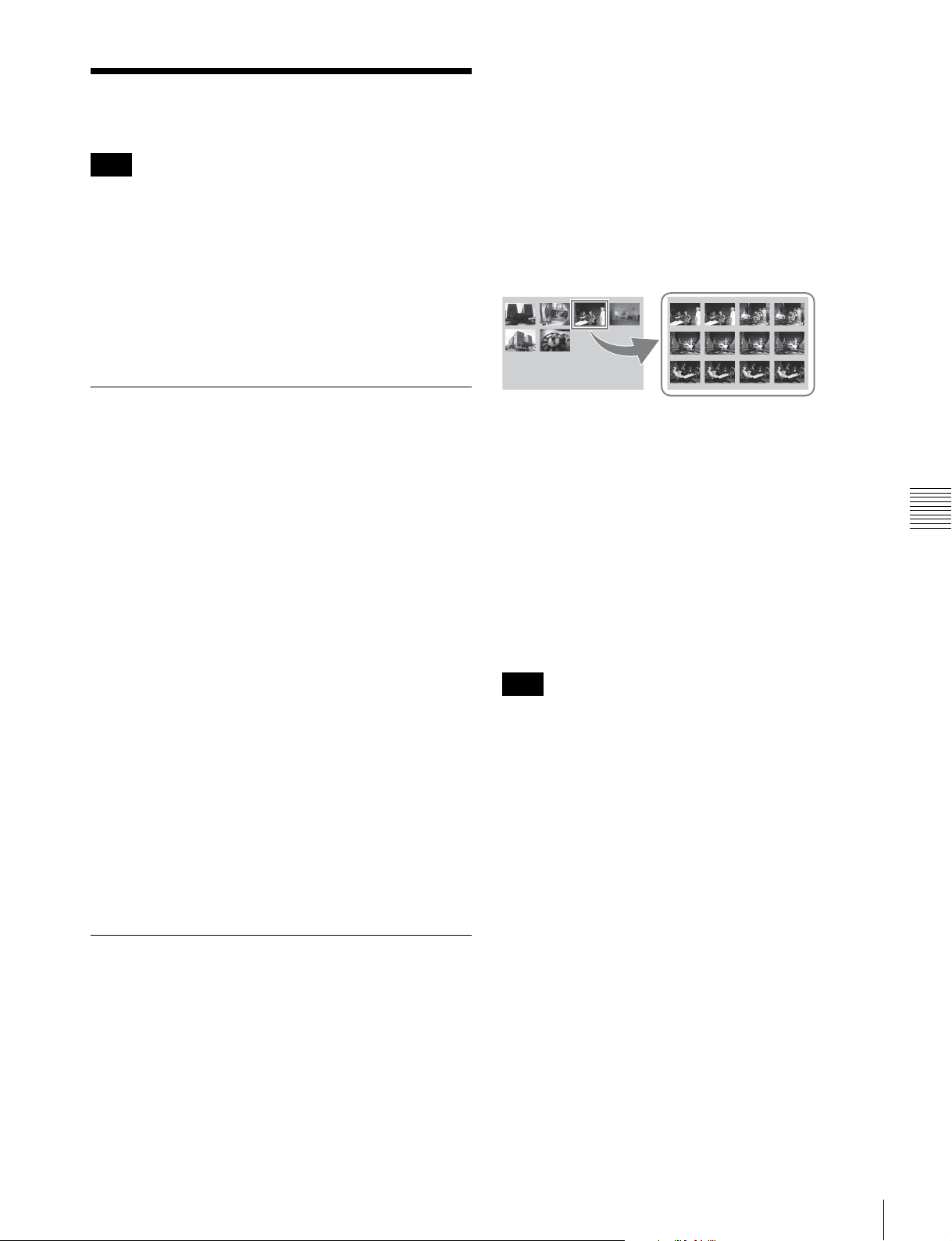
Clip Operations
Note
The following operations target only clips on internal
storage/Professional Disc. Before performing these
operations, be sure to set the Write-Inhibit tab on the disc
so as to enable recording. They cannot be executed for
clips on SxS memory cards.
• Set clip flags
• Lock/Unlock
• Delete
• Set the index picture frame
Selecting clips
Select clips with the selection frame (see page 59).
To move the selection frame
Do one of the following.
• Turn the PUSH SET knob.
• Press the arrow buttons.
• Turn the shuttle/jog dial. (The selection frame moves at
high speed in shuttle mode and at low speed in jog
mode.)
To play the clip you have found
Select the clip, and then press the PLAY button.
To search through a clip in the expand
thumbnail screen
The expand function allows you to divide a clip selected in
the clip list screen into equally sized blocks, and to display
a list of thumbnails of those blocks. This is a quick and
efficient way to review the selected clip and search for
target scenes. You can specify 12, 144, or 1728 divisions.
1
In the clip thumbnail screen, select the thumbnail of
the clip that contains the scene you want to find.
2
Press the EXPAND function button (F6).
The selected clip is divided into 12 blocks, and a list
appears in the expand thumbnail screen (see page 61)
with the first frame of each block displayed as a
thumbnail.
3
Select the thumbnail that you want to expand further.
Chapter 5 Operations in Clip List Screens
To jump to the first clip
Press the PREV button while holding down the SHIFT
button.
To jump to the last clip
Press the NEXT button while holding down the SHIFT
button.
To make a continuous selection of clips
Move the selection frame to the first clip that you want to
select. Then, while holding down the SHIFT button, turn
the PUSH SET knob.
To cancel the continuous selection, move the selection
frame without the SHIFT button held down.
Searching with thumbnails
You can put the clip list screen into thumbnails view (see
page 59) to search for desired clips while viewing
thumbnails.
To search for clips while viewing clip names, press the
DISPLAY button to switch to details view (see page 60).
To cue up the clip you have found
Select the clip, and then press the PUSH SET knob.
4
Repeat steps 2 and 3 up to 2 times, as required.
Note
If the duration of each block after division would be
shorter than one frame, division is performed so that an
expand thumbnail screen is displayed in which the
duration of each block is one frame. In this case, no such
expand thumbnail screen is displayed that represents
further expansion.
For example, a 100-frame clip is divided into 100 blocks
when you press the EXPAND function button (F6) twice
and an expand thumbnail screen is displayed in which the
duration of each block is one frame. A third press of the
EXPAND function button (F6) displays no expand
thumbnail screen representing further expansion.
To return to the previous expansion level
Press the EXPAND function button (F6) while holding
down the SHIFT button.
To display the expand thumbnail screen of the
previous or next clip
With the expand thumbnail screen still active, press the
PREV button or the NEXT button.
An expand thumbnail screen appears displaying the
thumbnails of 12 equal blocks resulting from division of
the previous or next clip.
Clip Operations
63
Page 64

Setting clip flags
You can set three types of clip flags (OK/NG/KP(KEEP))
for selected clips. Setting these flags in each clip that you
record makes it easy for editors and other colleagues to
find and select the clips that they need.
1
In a clip list screen, select the clip where you want to
set a flag (multiple selections possible).
2
Display the Clip Menu.
3
Select Set Clip Flag.
The Set Clip Flag screen appears.
In this screen, a x mark appears in front of the name
of each flag that is set in one or more of the currently
selected clips.
Chapter 5 Operations in Clip List Screens
4
Select the clip flag that you want to set (OK/NG/
KP(KEEP)), and then press the PUSH SET knob.
This step is not needed if you lock all clips.
2
Display the Clip Menu.
3
Select Lock Unlock Clips.
The Lock Unlock Clips screen appears.
4
Select Lock Selected Clips or Lock All Clips, and then
press the PUSH SET knob.
The clips selected in step 1 or all clips are locked.
A lock icon (see page 60) appears on the thumbnail of
the locked clips.
Tip
You can lock the selected clips by pressing the STOP
button while holding down the SHIFT button in step 1.
To unlock clips
The clip flag is set for all selected clips, and the clip
flag icon (see page 60) appears on thumbnails.
To clear clip flags
Carry out steps 1 to 3, selecting a clip that has a flag set,
and then select “none” in step 4.
Locking (write-protecting) clips
In a clip list screen, you can lock the selected clips so that
they cannot be deleted or altered.
Locking prevents the following operations on clips.
• Deletion
• Changing the index picture
• Adding and deleting shot marks
• Setting and clearing clip flags
Notes
• Locked clips are deleted along with other clips when a
media is formatted.
• Clips cannot be locked or unlocked when a media is
write protected.
To lock clips
1
In a clip list screen, select the clips that you want to
lock (multiple selections possible).
1
Execute the steps 1 to 3 in the previous section.
2
Select Unlock Selected Clips or Unlock All Clips, and
then press the PUSH SET knob.
3
Select “OK”, and then press the PUSH SET knob.
Tip
When you select a clip you want to unlock in the clip list
screen and then press the STOP button while holding down
the SHIFT button, a dialog appears asking you to confirm
unlock. When you select “OK” and press the PUSH SET
knob, the selected clip is unlocked. (To cancel unlock,
select “CANCEL” and press the PUSH SET knob.)
Deleting clips
Notes
• Clips cannot be deleted when a media is write protected.
• Locked clips cannot be deleted.
1
In a clip list screen, select the clips that you want to
delete (multiple selections possible).
This step is not needed if you delete all clips.
2
Display the Clip Menu.
64
Clip Operations
Page 65

3
Select Delete Clips.
The Delete Clips screen appears.
4
Select Delete Selected Clips or Delete All Clips, and
then press the PUSH SET knob.
5
Select “OK”, and then press the PUSH SET knob.
The clips selected in step 1 or all clips are deleted.
Tip
You can delete the selected clips by pressing the RESET
button while holding down the SHIFT button in step 1 and
by carrying out step 5.
To set another frame as the index picture frame
Select “CANCEL” and press the PUSH SET knob,
turning the confirmation box off. Start again from
step 1.
When you switch the display to the clip list screen, the
newly set index picture is displayed as the thumbnail.
Copying clips
See “Copy operations” (page 54) for information about
operations.
Setting the index picture frame
The clip thumbnail screen displays thumbnails as index
pictures for clips. Normally the index picture is the first
frame in a clip, but you can change it to any frame in the
clip for a different index picture.
Note
You cannot set index pictures for EDLs.
1
In the basic operation screen or video monitor screen,
play back the clip you want set the index picture frame.
2
Press the STOP button at the frame you want to be the
index picture frame, to obtain a still frame display.
3
Display the page P5 OTHER of the function menu,
and press the INDEX function button (F1).
Chapter 5 Operations in Clip List Screens
A confirmation box appears asking you whether to set
the frame of the still image as the index picture frame.
4
To set the current frame as the index picture frame,
select “OK” and press the PUSH SET knob.
Clip Operations
65
Page 66

Disc Operations
Finalizing discs
You can finalize write-once type Professional Discs.
The Clip Menu allows you to format (initialize) and
finalize a Professional Disc.
Formatting (initializing) discs
You can format recorded discs.
Note
You cannot format finalized discs.
1
Insert the disc you want to format into the disc slot.
2
Press the DISC button.
3
Switch the display to the clip list screen.
4
Press the MENU button to display the Clip Menu.
Chapter 5 Operations in Clip List Screens
5
Select “Format Disc” and press the PUSH SET knob.
A confirmation box appears asking you whether to
execute formatting.
6
To execute formatting, select “OK” and press the
PUSH SET knob.
The formatting starts, and the message “Format
Executing...” appears.
To cancel the formatting
Select “CANCEL” and press the PUSH SET knob.
When the formatting is completed, the message
“Format completed.” appears.
To format another disc
Remove the disc that has been formatted, and insert
another disc into the disc slot. When a confirmation
box has appeared asking if you want to execute
formatting, execute step 6 once more.
Notes
• You cannot write additional data to finalized discs.
• Finalized discs cannot be finalized again.
1
Insert the disc you want to finalize into the disc slot.
2
Select “disc” as media.
3
Switch the display to the clip list screen.
4
Display the Clip Menu.
5
Select “Finalize Disc” and press the PUSH SET knob.
A confirmation box appears asking you whether to
execute finalizing.
6
To execute finalizing, select “OK” and press the
PUSH SET knob.
The finalizing starts, and the message “Finalize
Executing....” appears.
To cancel the finalizing
Select “CANCEL” and press the PUSH SET knob.
When the finalizing is completed, the message
“Finalize completed.” appears.
To finalize another disc
Remove the disc that has been finalized, and insert
another disc into the disc slot. When a screen has
appeared asking if you want to execute formatting,
execute step 6 once more.
7
To quit finalizing, select “Exit” and press the PUSH
SET knob.
66
7
To quit formatting, select “Exit” and press the PUSH
SET knob.
Disc Operations
Page 67

File Operations
Overview
A remote computer can be connected to this unit and used
to operate on recorded data which has been saved in data
files, such as video and audio data files.
To perform file operations, use either of the following
methods to interconnect this unit and a computer.
• Make FTP connections (see page 69).
• Make CIFS connections (see page 73).
Directory structure
Chapter
6
The directory structure of the internal storage can be
selected with the maintenance menu item M33: FILE I/F
CONFIG >FOLDER STYLE.
To use a directory structure matching existing
XDCAM devices: Select “xdcam style”.
To use a directory structure supporting multiple
media: Select “xds style” (factory default setting).
The following figure shows the directory structure
example of the internal storage visible to a remote
computer.
Note
This structure is not the same as the actual structure
recorded on the internal storage.
File operation restrictions
This section explains which operations are possible on
files stored in each directory.
“Read” and “write” are defined as follows.
Read: Read data sequentially from the start to the end of
the file.
Write: Write data sequentially from the start to the end of
the file.
Chapter 6 File Operations
a) Root directory
Example when “xds style” is selected
Overview
67
Page 68

INTERNAL directory (xds style)/root directory (xdcam style)
File name Content Operations
Read Write Rename Create Delete
a)
DISCMETA.XML Contains metadata to indicate the internal storage
Ye s Ye s
properties.
MEDIAPRO.XML Contains a list of material on the internal storage,
Ye s N o N o N o N o
basic properties, related information, and information
about access methods.
SYSPRO.XML Contains information about device system settings
Ye s N o N o N o N o
and menu settings.
Other files Files other than the above – No – No –
No No No
a) Only files which can be written by XDS devices
• The directories in the INTERNAL directory (xds style)/
root directory (xdcam style) cannot be deleted or
Notes
renamed.
• Directories cannot be created in the INTERNAL
directory (xds style)/root directory (xdcam style).
Clip directory
File name Content Operations
Read Write Rename Create Delete
a)
*
.MXF
*
M01.XML
a)
Clip file created by recording (MXF file) Yes Yes
Metadata file generated automatically when *.MXF
Ye s Ye s
file is created.
a)
User metadata file. This type of file is generated
automatically during recording via an FTP connection
Ye s Ye s N o
Chapter 6 File Operations
*
M02.KLV
when the unit recognizes that an MXF file contains
metadata that was generated by a non-XDS device.
Other files Files other than the above – No – No –
a) The unit can handle files with user-defined names in the “*” part.
b) Only files which can be written by XDS devices
c) Overwriting is not possible.
d) When the “*” part of a *.MXF file name is changed, a *M01.XML file and
a *M02.KLV file with the same name in the “*” part are also changed
automatically.
e) When a *.MXF file is created, a *M01.XML file with the same name in
the “*” part is generated automatically.
f) When a *.MXF file is deleted, a *M01.XML file and a *M02.KLV file
with the same name in the “*” part are also deleted automatically.
Notes
• Directories cannot be created in the Clip directory.
• File names are not case-sensitive.
b), c)
b)
Ye s Ye s
d)
No
d)
No
Ye s
e)
b)
b)
Ye s
No
Ye s
f)
f)
Edit directory
File name Content Operations
Read Write Rename Create Delete
*
E01.SMI
*
M01.XML
a)
a)
EDL file Yes Yes
Metadata file generated automatically when
*
E01.SMI file is created.
Ye s Ye s
Other files Files other than the above – No – No –
a) The “*” part can be changed to a user-defined name.
b) Only files which can be written by XDS devices
c) When the “*” part of an “*E01.SMI” file name is changed, an *M01.XML
file with the same name in the “*” part is also changed automatically.
d) When an *E01.SMI file is created, an *M01.XML file with the same name
in the “*” part is also generated automatically.
e) When an *E01.SMI file is deleted, an *M01.XML file with the same name
in the “*” part is also deleted automatically.
68
Overview
Notes
• Directories cannot be created in the Edit directory.
• File names are not case-sensitive.
b)
b)
Ye s Ye s
c)
No
No
d)
b)
Ye s
No
e)
Page 69

FTP File Operations
File operations between this unit and a remote computer
can be carried out by the File Transfer Protocol (called
“FTP” below).
Preparations
1
Connect the network connectors of this unit and a
remote computer with a network cable (see
connections illustration on page 31). Or connect this
unit to the network to which the remote computer is
connected (see connections illustration on page 31).
2
Set the IP address and other network setting items for
this unit.
For details, see “To change network settings”
(page 96).
If network settings have already been made
Check the IP address of this unit.
For details, see “To check the assigned IP address”
(page 96).
1) This unit is able to acquire an IP address automatically from a DHCP
server. It also supports an Auto-IP function to assign an IP address
automatically when access from this unit to the DHCP server times
out. You can check DHCP settings and the assigned IP address on
page M5:NETWORK of the maintenance menu.
To connect a computer running Windows Vista or
Windows 7
Disable the Internet Protocol Version 6 (TCP/IPv6).
Windows Vista: (1) Open “Network and Sharing Center”
>“Manage network connections” >“Local Area
Connection” in the control panel. (2) In the “Local
Area Connection Properties”, uncheck the “Internet
Protocol Version 6 (TCP/IPv6)”, and then click the
OK button.
Windows 7: (1) Open “View network status and tasks”
>“Change adapter settings” >“Local Area
Connection” in the control panel. (2) In the “Local
Area Connection Properties”, uncheck the “Internet
Protocol Version 6 (TCP/IPv6)”, and then click the
OK button.
1)
This section explains how to use the command prompt. For
more information about using FTP client software, refer to
the documentation of the FTP client software on your
system.
To log in
1
Start the command prompt.
2
Enter “ftp <SP> <IP address>”, and press the Enter
key. (<SP> refers to a space.)
For example, if the IP address of this unit is set to
“192.168.001.010”, enter “ftp 192.168.1.10”.
Refer to the Windows help for more information about
the FTP command.
If the connection succeeds, you are prompted to enter
a user name.
3
Enter the user name “admin” and press the Enter key.
When the user name is verified, you are prompted to
enter a password.
4
Enter the password and press the Enter key.
The password is set to the model name (“xds-pd1000”
or “xds-pd2000”) when the unit is shipped from the
factory.
The login is complete when the password is verified.
See “Command list” (page 69) for the FTP protocol
commands supported by this unit.
If the connection times out
This unit terminates FTP connections if no command
is received within 90 seconds of the last command. If
this occurs, log out (see the next section) and repeat
steps 1 to 3.
Note
If you power this unit off during an FTP connection,
the data transferred thus far may be discarded.
To log out
To log out after finishing file operations, enter “QUIT” at
the command prompt and press the Enter key.
Chapter 6 File Operations
Making FTP connections
FTP connections between this unit and a remote computer
can be made with either of the following.
• The command prompt
• FTP client software
Command list
The FTP protocol commands supported by this unit
include standard commands (see the next section) and
extended commands (see page 72).
FTP File Operations
69
Page 70

Notes
• To execute FTP commands, you must install application
software such as XDCAM Browser on your computer.
• The commands supported by application software vary.
• An FTP client software that supports UTF-8 is required
to use Unicode characters other than ASCII characters.
Command prompt FTP commands do not support
UTF-8.
Standard commands
In the command syntax, <SP> means a space, entered by
pressing the space bar, and <CRLF> means a new line,
entered by pressing the Enter key.
USER
Send this command to begin the login process.
Command syntax: USER <SP> <user name> <CRLF>
Input example: USER admin
TYPE
Specifies the type of data to be transferred.
Command syntax: TYPE <SP> <type-code (options
delimited by <SP>)> <CRLF>
<type-code> can be any of the following. However, for
XDS devices, data is always transferred as “I”, regardless
of the type-code specification.
•A: ASCII
- N: Non-print
- T: Telnet format
- C: ASA Carriage Control
• E: EBCDIC
- N: Non-print
- T: Telnet format
- C: ASA Carriage Control
• I: IMAGE (Binary) (default)
• L: LOCAL BYTE
- SIZE: byte size
Input example: TYPE I
PASS
Send this command to complete the login process.
Command syntax: PASS <SP> <password> <CRLF>
Input example: PASS xds-1000
QUIT
Terminates the FTP connection. If a file is being
Chapter 6 File Operations
transferred, terminates after completion of the transfer.
Command syntax: QUIT <CRLF>
PORT
Specifies the IP address and port to which this unit should
connect for the next file transfer (for data transfer from this
unit).
Command syntax: PORT <SP> <h1,h2,h3,h4,p1,p2>
<CRLF>
• h1 (most significant byte) to h4 (least significant byte): IP
address
• p1 (most significant byte), p2 (least significant byte): Port
number
Input example: PORT 10,0,0,1,242,48
(IP address: 10.0.0.1, Port number: 62000)
STRU
Specifies the data structure.
Command syntax: STRU <SP> <structure-code>
<CRLF>
<structure-code> can be any of the following. However,
for XDS devices, the structure is always “F”, regardless of
the structure-code specification.
• F: File structure (default)
• R: Record structure
• P: Page structure
Input example: STRU F
MODE
Specifies the transfer mode.
Command syntax: MODE <SP> <mode-code> <CRLF>
<mode-code> can be any of the following. However, for
XDS devices, the mode is always “S”, regardless of the
mode-code specification.
• S: Stream mode (default)
•B: Block mode
• C: Compressed mode
Input example: MODE S
PASV
This command requests this unit to “listen” on a data port
(which is not its default data port). (It puts this unit into
passive mode, waiting for the remote computer to make a
data connection.)
Command syntax: PASV <CRLF>
70
FTP File Operations
LIST
Sends a list of files from this unit to the remote computer.
Command syntax: LIST <SP> <options> <SP> <path-
name> <CRLF>
<options> can be any of the following.
• -a: Also display file names that begin with “.”
• -F: Append “/” to directory names.
Page 71

The following data is transferred, depending on whether
<path-name> specifies a directory or file.
• Directory specified: A list of the files in the specified
directory
• File specified: Information about the specified file
• No specification: A list of the files in the current directory
The wildcard characters “*” (any string) and “?” (any
character) may be used in <path-name>.
Input example 1: LIST-a Clip
Input example 2: LIST Clip/*.MXF
NLST
Sends a list of file names from this unit to the remote
computer, with no other information.
Command syntax: NLST <SP> <options or path-name>
<CRLF>
The following options may be specified when no pathname is specified.
• -a: Also display file names that begin with “.”.
• -l: Also display information other than file name (gives the
same result as the LIST command).
• -F: Append “/” to directory names.
The following data is transferred, depending on whether
<path-name> specifies a directory or file.
• Directory specified: A list of the file names only in the
specified directory
• No specification: A list of the file names only in the current
directory.
The wildcard characters “*” (any string) and “?” (any
character) may be used in <path-name>.
Input example 1: NLST-l
Input example 2: NLST Clip/
RETR
*.MXF
Begins transfer of a copy of a file in the specified path on
this unit to the current directory on the remote computer.
Command syntax: RETR <SP> <path-name> <CRLF>
Input example: RETR Clip/CLIP00001.MXF
Notes
• For *.MXF files or *E01.SMI files, the UMID of the
copy source file is not saved. However, it is saved if an
immediately preceding SITE UMMD extended
command has been issued. For *E01.SMI files,
execution of the STOR command results in an error if
material with the same UMID already exists at the
transfer destination directory.
• For *.MXF files, some data, such as file header
metadata, may be missing.
• Depending on the transfer destination directory and the
file type, transfer may not be possible.
For details, see “File operation restrictions” (page 67).
Command syntax: STOR <SP> <path-name> <CRLF>
Input example: STOR Edit/E00001E01.SMI
RNFR
RNTO
Rename a file.
Specify the file to be renamed with the RNFR command,
and specify the new name with the RNTO command.
(Always follow a RNFR command with a RNTO
command.)
For details, see “File operation restrictions” (page 67).
Command syntax: RNFR <SP> <path-name (before
change)> <CRLF>
RNTO <SP> <path-name (after change)> <CRLF>
Input example: RNFR Clip/CLIP00001.MXF
RNTO Clip/News_digest.MXF
DELE
Deletes the specified file on this unit.
Note
Depending on the directory and file type, deletion may not
be possible.
Chapter 6 File Operations
STOR
Begins transfer of a copy of a file in the specified path on
the remote computer to the current directory on this unit.
Depending on the type of file transferred, the following
files are created.
• *.MXF file
-*M01.XML file (metadata)
-*M02.KLV file (user metadata)
• *E01.SMI file
-*M01.XML file (metadata)
For details, see “File operation restrictions” (page 67).
Command syntax: DELE <SP> <path-name> <CRLF>
Input example: DELE Clip/CLIP00099.MXF
STAT
Sends information about properties of the specified file, or
about data transfer status, from this unit to the remote
computer.
The following property information is sent, depending on
the file type.
• MXF file
- File name
- File type
FTP File Operations
71
Page 72

- CODEC type
- Frame rate
- Number of audio channels
- Duration
-UMID
• non-MXF file
- File name
Command syntax: STAT <SP> <path-name> <CRLF>
The following data is transferred, depending on whether a
file is specified with <path-name>.
• File specified: The properties of the specified file
• No specification:
Input example: STAT Clip/CLIP00001.MXF
1) Not supported in this version; always size 0.
1)
Moves to a directory as follows, depending on whether a
directory is specified with <path-name>.
• Directory specified: To the specified directory
• No specification: To the root directory
Input example: CWD Clip
CDUP
Moves one level up in the directory structure (makes the
parent of the current directory be the current directory).
Command syntax: CDUP <CRLF>
MKD
Creates a new directory.
ABOR
Requests this unit to abort a file transfer currently in
progress.
Command syntax: ABOR <CRLF>
SYST
Displays the system name of this unit.
Command syntax: SYST <CRLF>
HELP
Displays a list of the commands supported by this unit, or
an explanation of the specified command.
Chapter 6 File Operations
Command syntax: HELP <SP> <command-name>
<CRLF>
The following data is transferred, depending on whether a
command name is specified with <command-name>.
• Command name specified: Explanation of the specified
command.
• No specification: Command list
Input example: HELP RETR
Note
Some limitations apply to the creation of directories.
For details, see “File operation restrictions” (page 67).
Command syntax: MKD <SP> <path-name> <CRLF>
RMD
Deletes a directory.
Note
Some limitations apply to the deletion of directories.
For details, see “File operation restrictions” (page 67).
Command syntax: RMD <SP> <path-name> <CRLF>
Extended commands
In the Command syntax, <SP> means a space, entered by
pressing the space bar, and <CRLF> means a new line,
entered by pressing the Enter key.
NOOP
Does nothing except return a response. (Used to check
whether this unit is running.)
Command syntax: NOOP <CRLF>
PWD
Displays the current directory (“/” if the directory is the
root directory).
Command syntax: PWD <CRLF>
CWD
Changes the current directory (moves from the current
directory to another directory).
Command syntax: CWD <SP> <path-name> <CRLF>
72
FTP File Operations
SITE UMMD
When a *.MXF file is sent with the STOR command, the
copy source UMID is saved if this command is invoked
immediately before the STOR command.
Command syntax: SITE UMMD <CRLF>
If you make the transfer without issuing this command,
new UMID data is generated and added to the file.
SITE REPF
Transfers an MXF file existing in the specified path of this
unit to the current directory of the computer. This
command allows you to specify a section of the body of
MXF file (data comprised of video and audio) and transfer
that section only.
Page 73

Notes
• You cannot specify such section that exceeds the file
size.
• If the file name character string contains one or more
spaces, this command cannot be used. Use the SITE
REPFL command.
Command syntax: SITE REPF <SP> <path-name> <SP>
<start frame> <SP> <transfer size> <CRLF>
<start frame> specifies the offset of the video frame to start
transfer with respect to the top of the file (“0” for the top
frame).
<transfer size> specifies the number of video frames to
transfer (specifies “0” to perform transfer of data up to the
end of the file).
Input example: SITE REPF Clip/C0001.MXF 5 150
Transfer C0001.MXF. For the body, however,
data from sixth frame through 150th frame is only
transferred.
SITE REPFL
Transfers an MXF file existing in the specified path of this
unit to the current directory of the computer. This
command allows you to specify a section of the body of
MXF file (data comprised of video and audio) and transfer
that section only.
CIFS File Operations
You can perform file operations using the Common
Internet File System (CIFS) between this unit and the
computer.
Preparations
See “Preparations” under “FTP File Operations”
(page 69).
Making CIFS connections
CIFS connections between this unit and a Windows
computer can be made with either of the following.
• Use Windows Explorer to map this unit as a network
drive
• Refer to this unit directly from Windows Explorer
The following describes the procedure for using Windows
Explorer to map this unit as a network drive.
1
Start Windows Explorer.
Note
You cannot specify such section that exceeds the file size.
Command syntax: SITE REPFL <SP> “<path-name>”
<SP> <start frame> <SP> <transfer size> <CRLF>
<path-name> specifies the file path name by enclosing it in
double quotation marks (“ ”).
<start frame> specifies the offset of the video frame to start
transfer with respect to the top of the file (“0” for the top
frame).
<transfer size> specifies the number of video frames to
transfer (specifies “0” to perform transfer of data up to the
end of the file).
Input example: SITE REPFL “Clip/sakura 0001.MXF” 5 150
Transfer sakura 0001.MXF. For the body,
however, data from sixth frame through 150th
frame is only transferred.
2
In the Tools menu, select “Map Network Drive...”.
The Map Network Drive dialog appears.
3
Enter “\\<IP address>\xds\” in the “Folder” field.
For example, if the IP address of this unit is set to
“192.168.001.010”, enter “\\192.168.1.10\xds\”.
4
Click on “Connect using a different name”.
The Connect As... dialog appears.
5
Enter the user name “admin” and the password, and
click OK.
The password is set to the model name (“xds-pd1000”
or “xds-pd2000”) when the unit is shipped from the
factory.
6
Click Finish.
The network drive allocation is complete when the
password is verified.
To break the connections
In Windows Explorer, select the network drive and rightclick it, then click “Disconnect”.
Chapter 6 File Operations
CIFS File Operations
73
Page 74

Menus
Chapter
7
Menu System Configuration
The settings for this unit use the following menus.
Setup menu
The setup menu system of this unit comprises the basic
setup menu and extended setup menu.
Maintenance menu
This provides audio control, and network and setup menu
settings, and also shows version information.
For details, see “Maintenance Menu” (page 92).
Function menu
For details, see “Basic Operations of the Function Menu”
Chapter 7 Menus
(page 41).
Clip Menu
For details, see “Clip Menu” (page 61).
Setup Menu
The setup menu system of this unit comprises the basic
setup menu and extended setup menu.
Basic menu
This menu is used to make settings relating, for example,
to the following.
- the operating hours meter
- the text information superimposed on the video output
to the monitor
- the menu banks for retaining menu settings
Extended menu
This menu is used to make a wide range of settings
relating to the functions of this unit, for example, the
control panel functions, video and audio control, and
digital data processing.
Configuration of the basic menu
The basic menu comprises the following groups of items.
Item group Function Refer to
Items
H01 to H19
Items
001 to 099
Items
B01 to B20
Display of the total number of
hours the unit has been
powered on, and other
information collected by the
operating hours meter
Settings relating to the
superimposed text information,
switching between 59.94i/
59.94P/29.97P/50i/50P/25P
modes, etc.
Settings relating to the menu
banks for saving menu settings
page 100
page 75
page 77
74
Menu System Configuration / Setup Menu
Configuration of the extended menu
The extended menu comprises the following groups of
items.
Page 75

Item group Function Refer to
Items
100 to 199
Items
200 to 299
Items
300 to 399
Items
600 to 649
Settings relating to control
panels
Settings relating to the remote
control interface
Settings relating to editing
operations
Settings relating to the
timecode generator
page 79
page 79
page 80
page 80
Items in the basic menu
Item group Function Refer to
Items
650 to 699
Items
700 to 799
Items
800 to 899
Items
900 to 999
Settings relating to the
metadata and UMID
Settings relating to video
control
Settings relating to audio
control
Settings relating to digital
processing
page 82
page 83
page 85
page 86
The basic menu items (excluding the items related to the
operating hours meter) are listed in the following table.
the value shown in menu screens (when they differ from
the values shown in settings screens).
• The underlined values are the factory defaults.
• The values in the “Settings” column are the values that
appear in settings screens. The values in brackets [ ] are
Item number Item name Settings
002 CHARACTER H-POSITION Adjust the horizontal screen position (as a hexadecimal value) of the text
information output from the HD-SDI OUTPUT 2 (SUPER), SD-SDI OUTPUT
2 (SUPER), HD-SDI MONITOR, SD-SDI MONITOR, or COMPOSITE
OUTPUT 2 (MONITOR) connector for superimposed display on the monitor.
The hexadecimal value 00 is for the far left of the screen. Increasing the
value moves the position of the characters to the right.
00 to 0C
00 to 0B
Set this item by adjusting to the required position while viewing the monitor.
003 CHARACTER V-POSITION Adjust the vertical screen position (as a hexadecimal value) of the text
information output from the HD-SDI OUTPUT 2 (SUPER), SD-SDI OUTPUT
2 (SUPER), HD-SDI MONITOR, SD-SDI MONITOR, or COMPOSITE
OUTPUT 2 (MONITOR) connector for superimposed display on the monitor.
The hexadecimal value 00 is for the top of the screen. Increasing the value
lowers the position of the characters.
00 to 2A
00 to 29
to 28 (When the number of system lines is 1080 and the
system frequency is 59.94i, 29.97P, 50i, 25P, or 23.98P)
to 28 (When the number of system lines is 720 and the system
frequency is 59.94P or 50P)
to 32 (When the number of system lines is 1080 and the
system frequency is 59.94i, 29.97P, 50i, 25P, or 23.98P)
to 32 (When the number of system lines is 720 and the system
frequency is 59.94P or 50P)
Chapter 7 Menus
005 DISPLAY INFORMATION
SELECT
Set this item by adjusting to the required position while viewing the monitor.
Determine the kind of text information to be output from the HD-SDI
OUTPUT 2 (SUPER), SD-SDI OUTPUT 2 (SUPER), HD-SDI MONITOR,
SD-SDI MONITOR, or COMPOSITE OUTPUT 2 (MONITOR) connector.
time data & status [T&sta]
time data & UB [T&UB]: Time data and user bits data. (When “UB” (user
bits data) is selected with CNTR SEL on the HOME page of the function
menu, the “user bits data” and “time data” arranged in that order are
displayed.)
time data & CNT [T&CNT]: Time data and counter count. (When
“COUNTER” is selected with CNTR SEL on the HOME page of the
function menu, the counter count and time data arranged in that order
are displayed.)
time data & timecode [T&T]: Time data and timecode (TC or VITC)
time data only [time]: Time data only
: Time data and the units status.
Setup Menu
75
Page 76

Item number Item name Settings
006 LOCAL FUNCTION ENABLE Determine which recording and playback control buttons on the front panel
are enabled when this unit is controlled from external equipment via a
REMOTE (9P) connector.
all disable [dis]: All buttons and switches are disabled.
stop & eject [st&ej]
: Only the STOP button and the EJECT button can
operate.
all enable [ena]: All buttons and switches are enabled.
013 SYSTEM FREQUENCY
SELECT MENU
Specify whether to enable switching the system frequencies (1080/59.94i,
50i, 29.97P, 25P, 23.98P or 720/59.94P, 50P).
: Do not enable switching the system frequencies.
off
on: Enable switching the system frequencies.
For details about switching the system frequencies, see page 37.
Note
Settings for both basic and extended menu items are saved separately for
different system frequencies.
• 1080 59.94i/29.97P
• 1080 50i/25P
• 1080 23.98P
• 720 59.94P
• 720 50P
Therefore, when you switch system frequencies, all menu items are reset to
the current settings for the new mode. (They are different from the setting for
the previous mode.)
027 SD CHARACTER Specify whether to superimpose text information on the SD video signal.
Sub-item
1SD-SDI2
a)
Specify whether to superimpose text information on the video signal output
from the SD-SDI OUTPUT 2 (SUPER) connector.
off: Do not superimpose.
: Superimpose.
on
2 MONITOR SD
a)
Specify whether to superimpose text information on the video signal output
from the SD-SDI MONITOR OUTPUT or COMPOSITE OUTPUT 2
(MONITOR) connector.
off: Do not superimpose.
: Superimpose on the outputs from both the above connectors.
Chapter 7 Menus
all
comp: Superimpose on the output from the COMPOSITE OUTPUT 2
(MONITOR) connector.
sdi: Superimpose on the output from the SD-SDI MONITOR OUTPUT
connector.
3 LCD/VGA Specify whether to superimpose text information over the display on the
front panel, and on the video signal output from the MONITOR (VGA)
connector.
off: Do not superimpose.
: Superimpose.
on
028 HD CHARACTER Specify whether to superimpose text information on the HD video signal.
Sub-item
1 HD-SDI2 Specify whether to superimpose text information on the video signal output
from the HD-SDI OUTPUT 2 (SUPER) connector.
off: Do not superimpose.
: Superimpose.
on
2 MONITOR HD Specify whether to superimpose text information on the video signal output
from the HD-SDI MONITOR OUTPUT connector.
off: Do not superimpose.
: Superimpose.
sdi
031 RECORDING FORMAT Set the recording format.
: HD422
HD422
420HQ: HD420HQ
IMX 50Mbps [IMX50]: IMX 50Mbps
DVCAM: DVCAM
76
Setup Menu
Page 77

Item number Item name Settings
B01 RECALL SETUP BANK-1 Set to “on” to recall menu bank 1 to replace the current menu settings.
B02 RECALL SETUP BANK-2 Set to “on” to recall menu bank 2 to replace the current menu settings.
B03 RECALL SETUP BANK-3 Set to “on” to recall menu bank 3 to replace the current menu settings.
B11 SAVE SETUP BANK-1 Set to “on” to save current menu settings to menu bank 1.
B12 SAVE SETUP BANK-2 Set to “on” to save current menu settings to menu bank 2.
B13 SAVE SETUP BANK-3 Set to “on” to save current menu settings to menu bank 3.
B20 RESET SETUP MENU Set to “on” to return the settings of the current menu to the factory default
a) Not displayed when the unit is in 23.98P mode.
settings.
Basic menu operations
Setup menus are displayed on the video monitor screen or
on a PC monitor connected to the MONITOR connector.
To display the setup menu
MENU button
PUSH SET knob
RESET button
Function buttons (F1 to F6)
To display a setup menu, press the MENU button.
The currently selected menu item is displayed in reverse
video.
Buttons used to change settings
Use the following buttons to change setup menu settings.
Menu control
buttons
MENU button Displays and hides the setup and user
PUSH SET knob • When turned clockwise or
Function buttons
F1 to F6
(The function to
be displayed
varies depending
on the situations.)
RESET button • Returns the current setting to the
Functions
interface menus.
counterclockwise, moves the reverse
video to select the item to change.
• When turned clockwise or
counterclockwise, changes a menu
item setting.
• When pressed, answers “Yes” to a
question.
RETURN: Goes up one level.
SELECT: Selects an item.
UP: Skips back 100 or 50 items in the
list of menu items.
DOWN: Skips forward 100 or 50 items
in the list of menu items.
SAVE: Saves a new setting to memory.
EXIT: Exits the current menu.
–: Changes a setting.
+: Changes a setting.
factory default.
• Answers “No” to a question.
Chapter 7 Menus
Currently selected item
Group name for the currently selected item
To change the settings of menu items
Proceed as follows to change the settings of menu items.
1
Use the PUSH SET knob to select the required item.
Example: Screen display when item 005 DISPLAY
SEL is selected
Setup Menu
77
Page 78

Current setting
2
Press the PUSH SET knob or the SELECT function
button (F2).
This displays the setting screen for the menu item
selected in step 1.
Example: Setting screen display when item 005
DISPLAY INFORMATION SELECT is selected
sure to press the SAVE function button (F5) after
making the settings.
To return menu settings to their factory
default settings
After changing menu settings, use the following procedure
to return the settings to their factory default settings
(setting initialization).
To return a particular setting to its factory default
setting
In the screen that selects the setting of that item, press the
RESET button.
For example, proceed as follows to return the 005
DISPLAY INFORMATION SELECT item to its default
setting. This assumes that the setting has been changed
from the factory default “time data & status” in step 3 of
the procedure in “To change the settings of menu items”
(page 77).
1
Press the RESET button.
“time data & status” (factory default setting) is
selected.
Current setting
3
Use the PUSH SET knob or the +/– function button
(F3 or F4) to change the setting.
Chapter 7 Menus
Turning the PUSH SET knob while holding down the
SHIFT button increases the increment of adjustment.
4
To change other settings, press the PUSH SET knob or
the RETURN function button (F1) to return to the
previous screen, then repeat steps 1 to 3.
5
When you have completed the settings, press the
SAVE function button (F5).
The message “NOW SAVING...” appears on the video
monitor screen, while the new settings are saved in
memory. When the saving operation is completed, the
video monitor screen returns to its normal indications.
Notes
• If you power off the unit before a save operation is
completed, settings may be lost. Wait until the save is
completed before powering off the unit.
• If, instead of pressing the SAVE function button (F5),
you press the MENU button, the new settings are not
saved. The message “ABORT !” appears on the video
monitor screen for about 0.5 seconds, and the system
exits the menus. To change more than one setting, be
2
Press the SAVE function button (F5).
The setting returned to its factory default is saved in
memory as the current setting.
To return all settings to their factory default
settings
1
Press the MENU button to display the setup menu.
2
Press the RESET button.
The message “INITIALIZE ALL ITEMS TO
FACTORY PRESET VALUES?” appears, to confirm
whether you wish to return all settings to their factory
default settings.
3
Press the SAVE function button (F5).
The message “NOW SAVING...” appears on the video
monitor screen, while the settings of all items are
returned to their factory default settings. These factory
default settings are saved in memory.
If you power off the unit while settings are being
saved, settings may not be correctly returned to their
factory default settings. Wait until the saving is
completed before powering off the unit.
To abandon the resetting operation
Instead of pressing the SAVE function button (F5),
press the RESET button.
The display returns to the top level of the setup menu,
leaving the settings unchanged.
78
Setup Menu
Page 79

Items in the extended menu
The following tables show the items in the extended menu.
• The values in the “Settings” column are the values that
appear in settings screens. The values in brackets [ ] are
Menu items in the 100s, relating to the control panels
Item number Item name Settings
101 SELECTION FOR SEARCH DIAL
ENABLE
114 AUDIO MONITOR OUTPUT LEVEL Select whether to control the level of the audio signal output from the
121 FRAME PB MODE Select the variable-speed playback field/frame mode.
130 DISPLAY DIMMER CONTROL Set the brightness of the indication on the LCD.
131 AUDIO VOLUME Select whether each of the CH-1/ALL CH, CH-2 to CH-4 adjustment
155 STREAM CHASE Specify whether perform chase output with CIFS during recording.
Select how the unit enters the shuttle, jog, or variable-speed mode.
dial direct [dial]
during recording/editing, turn the jog dial or shuttle dial.
via search key [key]: Press the SHTL/JOG or VAR/JOG button.
AUDIO MONITOR OUTPUT R, L connectors with the LEVEL adjustment
knob for the PHONES jack.
variable [var]: Control.
: Do not control.
fixed
: Field playback
auto
frame: Frame playback.
Compared to field playback, frame playback gives more detail during
playback of still pictures.
10%, 25%, 50%, 75%
knobs on the control panel is effective to control the audio recording level
and playback level on each channel or the CH-1/ALL CH adjustment
knob alone functions as a master control to control the audio level on all
channels together.
: Each of the CH-1/ALL CH, CH-2 to CH-4 adjustment knobs is
each
effective to control each channel.
all: The CH-1/ALL CH adjustment knob alone functions as a master
control.
When “all” is selected, the ALL CH indicator under the CH-1/ALL CH
adjustment knob lights up.
disable (disc style) [disc]
(perform output in an MXF format compatible with existing devices).
enable (growing style) [ena]: Perform chase output with CIFS (perform
output in the MXF format unique for chase output).
the value shown in menu screens (when they differ from
the values shown in settings screens).
• The underlined values are the factory defaults.
: Press the SHTL/JOG or VAR/JOG button or, except
, 100%
: Do not perform chase output with CIFS
Chapter 7 Menus
This unit supports MXF V1.3 format.
MXF V1.3 format supports chase output by enabling data in the header
metadata area storing information on clip length, etc. to the footer
partition at the end of the MXF file as well as to the header partition. This
enables clips being recorded to be output via CIFS and handled on the
network.
Note
When using a nonlinear editor that is not a Sony product, please contact
the maker to confirm whether it is possible or not to receive clips output
by the chase output function using MXF V1.3 format.
Menu items in the 200s, relating to the remote control interface
Item number Item name Settings
208 PROTOCOL FOR REMOTE(9P) Select the protocol used with a REMOTE (9P) connector, for each port.
Sub-item
1 #2 (PB) Select the protocol used with the playback port.
VTR: Sony 9-pin VTR protocol
: VDCP protocol
VDCP
Setup Menu
79
Page 80

Menu items in the 200s, relating to the remote control interface
Item number Item name Settings
212 VIDEO REMOTE CONTROL
SELECT
a)
Select the method used to control the internal digital video processor
and to make related settings.
: Use the setup menu to change settings.
menu
remote (down converter) [dc]: Control the down-converter from an
HKDV-900 or another device connected to the VIDEO CONTROL
connector.
remote (up converter) [uc]: Control the up-converter from an HKDV-
900 or another device connected to the VIDEO CONTROL
connector.
a) Not displayed when the unit is in 23.98P mode.
Menu items in the 300s, relating to editing operations
Item number Item name Settings
320 DIGITAL AUDIO PB PROCESS ON
EDIT POINT
Specify the handling of audio at clip joints.
cut: Carry out a cut (possibly resulting in audio discontinuities at the edit
point).
: Fade out and fade in.
fade
Menu items in the 500s, relating to the disc drive
Item number Item name Settings
501 STILL TIMER To protect the disc against shock and vibrations, and to lengthen the life
of the laser diodes, the unit automatically enters standby off mode
whenever a specified time elapses in a disc stop mode (stop mode or the
still picture mode of search mode).
This allows you to set the time after which the unit exits a disc stop mode
and enters standby off mode.
0.5 sec [0.5 s] to 8 min [8 m] to 30 min [30 m]: Can be set in the range
from 0.5 seconds to 30 minutes.
off: Do not put into standby off mode.
Menu items in the 600s, relating to the timecode, metadata, and UMID
Item number Item name Settings
Chapter 7 Menus
601 VITC POSITION
SEL-1
a)
In 59.94i/59.94P/
29.97P mode
In 50i/50P/25P
mode
Select the line into which to insert VITC signals (SD output)
12H to 16H
to 20H: Any line from line 12 through line 20.
Notes
• You can insert VITC signals in two places. To insert in two places, set
both item 601 and item 602.
• In 59.94i/59.94P/29.97P mode (J), output of wide picture information is
given priority if OUTPUT in setup menu item 731 is set to “auto” and the
VITC insertion line is set to line 16.
• In 59.94i/59.94P/29.97P mode (UC), output of wide picture information
is given priority if OUTPUT in setup menu item 731 is set to “auto” and
the VITC insertion line is set to line 20.
Select the line into which to insert VITC signals (SD output)
9H to 19H
to 22H: Any line from line 9 through line 22.
Note
You can insert VITC signals in two places. To insert in two places, set
both item 601 and item 602.
80
Setup Menu
Page 81

Menu items in the 600s, relating to the timecode, metadata, and UMID
Item number Item name Settings
602 VITC POSITION
SEL-2
a)
In 59.94i/59.94P/
29.97P mode
Select the line into which to insert VITC signals (SD output)
12H to 18H to 20H: Any line from line 12 through line 20.
Notes
• You can insert VITC signals in two places. To insert in two places, set
both item 601 and item 602.
• In 59.94i/59.94P/29.97P mode (J), output of wide picture information is
given priority if OUTPUT in setup menu item 731 is set to “auto” and the
VITC insertion line is set to line 16.
• In 59.94i/59.94P/29.97P mode (UC), output of wide picture information
is given priority if OUTPUT in setup menu item 731 is set to “auto” and
the VITC insertion line is set to line 20.
In 50i/50P/25P
mode
Select the line into which to insert VITC signals (SD output)
9H to 21H
to 22H: Any line from line 9 through line 22.
Note
You can insert VITC signals in two places. To insert in two places, set
both item 601 and item 602.
605 TCG REGEN MODE Select the signal to be regenerated when the timecode generator is in the
regeneration mode.
TC&UB
: Both the timecode and user bits are regenerated.
TC: Only the timecode is regenerated.
UB: Only the user bits are regenerated.
607 U-BIT BINARY GROUP FLAG Select the user bits to be used in the timecode generated by the
timecode generator.
000:not specified [000]
: Character set not specified.
001:iso character [001]: 8-bit characters compliant with ISO 646 and
ISO 2022.
010:unassigned-1 [010]: Undefined.
011:unassigned-2 [011]: Undefined.
100:unassigned-3 [100]: Undefined.
101:page / line [101]: SMPTE-262M page/line multiplex system.
110:unassigned-4 [110]: Undefined.
111:unassigned-5 [111]: Undefined.
618 UPCONV EMBEDDED VITC
a)
Select the source of the VITC embedded into output HD-SDI signal when
up converting during playback of an SD clip.
: Select the VITC of the SD clip.
VITC
LTC: Select the LTC of the SD clip.
619 VITC
a)
Select whether to record the VITC generated by the internal timecode
generator during IMX recording.
off: Do not record the internally generated VITC.
: Record the internally generated VITC.
on
Chapter 7 Menus
Note
Even if this item is set to “off”, VITC is recorded if the input video signal
contains VITC and the VITC line is set to “throu” in menu item 723.
Setup Menu
81
Page 82

Menu items in the 600s, relating to the timecode, metadata, and UMID
Item number Item name Settings
638 TIME CODE FOR VDCP CONTROL Make a setting for timecode generated when the REC INIT command or
CUE WITH DATA command is executed from a VDCP-compliant
controller.
REC:VDCP PB:TC [VDCP]
: Recording timecode is continuous timecode
starting from 00:00:00:00 generated in accordance with the VDCP
controller. Timecode for cueing is the same as clip timecode.
REC:TCG PB:TC [menu]: Timecode for recording depends on the
settings of the menu items related to the timecode generator.
Timecode for cueing is the same as clip timecode.
REC:VDCP PB:Zero Base [VDCP/0]: Recording timecode is continuous
timecode starting from 00:00:00:00 generated in accordance with the
VDCP controller. Timecode for cueing is generated taking
00:00:00:00 as the timecode value of the clip’s first frame.
REC:TCG PB:Zero Base [menu/0]: Timecode for recording depends on
the settings of the menu items related to the timecode generator.
Timecode for cueing is generated taking 00:00:00:00 as the
timecode value of the clip’s first frame.
651 UMID SDI OUTPUT Select whether to output UMID in the VANC of the SDI output.
off: Do not output.
: Output.
on
See “Using UMID Data” (page 113) for more information about UMID.
652 UMID SD VANC LINE
a)
Select the line in which UMID is output when menu item 651 is set to
“on”.
12H, 13H, 15H, 16H, 17H
9H, 10H, 12H, 13H, 14H, 15H, 16H, 17H
, 18H, 19H (59.94i/59.94P/29.97P mode)
, 18H (50i/50P/25P mode)
See “Using UMID Data” (page 113) for more information about UMID.
653 UMID HD VANC LINE Select the line in which UMID is output when menu item 651 is set to
“on”.
9H to 17H
9H to 17H
to 20H (59.94i, 50i, 29.97P, 25P, 23.98P mode)
to 25H (59.94P, 50P mode)
See “Using UMID Data” (page 113) for more information about UMID.
657 ESSENCE MARK SDI OUTPUT Select whether to output essence marks in the SDI output VANC.
Chapter 7 Menus
660 ESSENCE MARK SD VANC LINE
off: Do not output.
: Output.
on
a)
Select the line to which to output essence marks when menu item 657 is
set to “on”.
12H, 13H, 15H, 16H, 17H
9H, 10H, 12H, 13H, 14H, 15H, 16H, 17H
, 18H, 19H (59.94i/59.94P/29.97P mode)
, 18H (50i/50P/25P mode)
665 ESSENCE MARK HD VANC LINE Select the line to which to output essence marks when item 657 is set to
“on”.
9H to 17H
9H to 17H
to 20H (59.94i, 50i, 29.97P, 25P, 23.98P mode)
to 25H (59.94P, 50P mode)
666 METADATA ITEM OUT Specify whether to include the information from recorded VANC packets
in data items in the DATA ITEM section of MXF files.
off: Do not include VANC packet information in DATA ITEM.
: Include VANC packet information in DATA ITEM.
on
668 USER META DATA OUTPUT IN
MXF
Select whether to output user metadata to MXF files.
off: Do not output.
: Output.
on
a) Not displayed when the unit is in 23.98P mode.
82
Setup Menu
Page 83
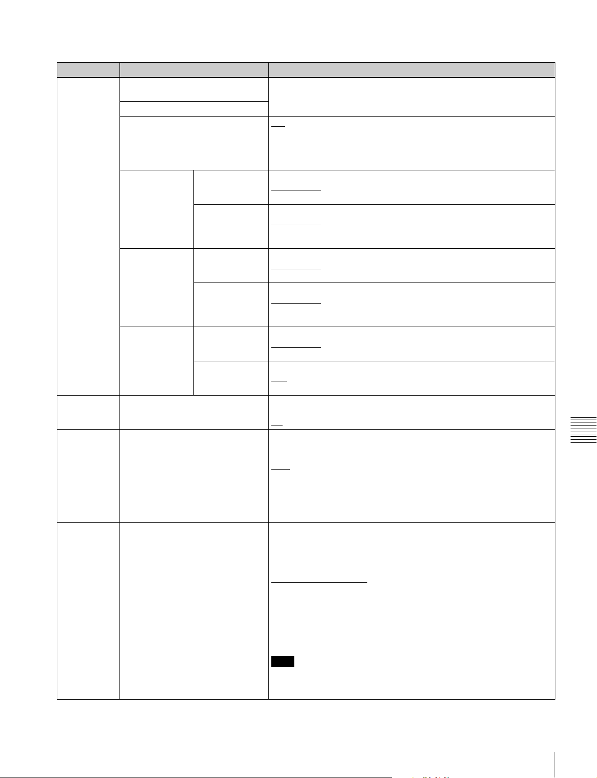
Menu items in the 700s, relating to video control
Item number Item name Settings
703 BLANK LINE SELECT
a)
Switch blanking of the video output signal on or off for individual lines in
the vertical blanking interval.
Sub-item The Y/C signal and odd/even fields are blanked simultaneously.
ALL LINE - - -
: Specify the blanking for each line separately.
blank [blnk]: Regardless of the setting of other sub-items, blank all lines
which can be specified in this menu item.
throu [thru]: Regardless of the setting of other sub-items, switch off
blanking for all lines which can be specified in this menu item.
In 59.94i/59.94P/
29.97P mode
(UC)
LINE 12 ...
LINE 19
Specify blanking for lines 12 to 19.
blank [blnk]
throu [thru]: Switch off blanking.
LINE 20 Specify blanking for line 20.
blank [blnk]
half: Carry out half-blanking.
throu [thru]: Switch off blanking.
In 59.94i/59.94P/
29.97P mode (J)
LINE 12 …
LINE 20
Specify blanking for lines 12 to 20.
blank [blnk]
throu [thru]: Switch off blanking.
LINE 21 Specify blanking for line 21.
blank [blnk]
half: Carry out half-blanking.
throu [thru]: Switch off blanking.
In 50i/50P/25P
mode
LINE 9 ...
LINE 22
Specify blanking for lines 9 to 22.
blank [blnk]
throu [thru]: Switch off blanking.
LINE 23 Specify blanking for line 23.
: Carry out half-blanking.
half
throu [thru]: Switch off blanking.
705 EDGE SUBCARRIER REDUCER
MODE
a)
707 FORCED VERTICAL
INTERPOLATION OFF
Select whether to enable the edge subcarrier reducer (ESR).
on: Enable ESR.
: Do not enable ESR.
off
The “Y-add” function is normally switched on automatically during jog or
variable-speed playback. This item selects whether to force the “Y-add”
function off.
: Automatically switch the “Y-add” function on.
auto
forced YADD off [off]: Force the “Y-add” function off.
: Carry out blanking.
: Carry out blanking.
: Carry out blanking.
: Carry out blanking.
: Carry out blanking.
Chapter 7 Menus
710 INTERNAL VIDEO SIGNAL
GENERATOR
The “Y-add” function is a circuit operation to interpolate the video signal
vertically during jog or variable speed playback for the purpose of
reducing the vertical movement of the playback picture.
Select the test signal to be output from the internal test signal generator.
When INT SG on page P1 INPUT of the function menu is set to “ON”,
the internal test signal generator operates to output the selected test
signal. This signal can also be recorded.
Off [OFF]: Do not output test signal.
75% Color Bars [CB75]
: 75% color bar signal
100% Color Bars [CB100]: 100% color bar signal
Multi Burst [MLTBS]: Multi-burst signal
10 steps [10STP]: 10-step signal
Pulse and Bar [PLSBR]: Pulse and bar signal
Ramp [RAMP]: Ramp signal
Black [BLACK]: Black signal
ARIB Color Bars [ARBCB]: ARIB color bar signal (modify width: 100%)
Note
“ARIB Color Bar” cannot be specified when SD recording is selected. If
“ARIB Color Bar” is selected, the selection is changed to “75% Color
Bars” ([CB75]).
Setup Menu
83
Page 84

Menu items in the 700s, relating to video control
Item number Item name Settings
713 VIDEO SETUP REFERENCE Set the video setup amount to be added to the composite output signal
Sub-item
OUTPUT LEVEL In 59.94i/59.94P/
29.97P mode
(in 59.94i/59.94P/29.97P mode only).
Add the setup level selected by this item to the output signal.
0.0%, 7.5
%
(UC)
In 59.94i/59.94P/
29.97P mode (J)
715 VIDEO GAIN CONTROL
a)
Add the setup level selected by this item to the output signal.
0.0%, 7.5%
Adjust the video output level of SD video signals output from the SD-SDI
OUTPUT, COMPOSITE OUTPUT, or HDMI OUTPUT connectors.
to 848
716 CHROMA GAIN CONTROL
a)
–2048 to 0
Adjust the chroma output level of SD video signals output from the SD-
SDI OUTPUT, COMPOSITE OUTPUT, or HDMI OUTPUT connectors.
to 848
717 CHROMA PHASE CONTROL
a)
–2048 to 0
Adjust the chroma phase of SD video signals output from the SD-SDI
OUTPUT, COMPOSITE OUTPUT, or HDMI OUTPUT connectors.
to 127
to 272
718 SETUP LEVEL (59.94i/59.94P/
29.97P mode)/BLACK LEVEL (50i/
25P mode)
719 SYSTEM PHASE SYNC
a)
a)
–128 to 0
Adjust the setup level (black level) of SD video signals output from the
SD-SDI OUTPUT, COMPOSITE OUTPUT, or HDMI OUTPUT
connectors.
–272 to 0
Adjust the sync phase of SD video signals output from the SD-SDI
OUTPUT, COMPOSITE OUTPUT, or HDMI OUTPUT connectors.
to 127
720 SYSTEM PHASE SC
a)
–128 to 0
Adjust the subcarrier phase of SD video signals output from the SD-SDI
OUTPUT, COMPOSITE OUTPUT, or HDMI OUTPUT connectors.
to 511
0
723 INPUT VIDEO BLANKING Switch blanking on or off for lines in the vertical blanking interval of input
video signals. Lines can be specified individually. Y/C signals and odd/
even fields are blanked simultaneously.
Sub-item
1 ALL LINE ---
Chapter 7 Menus
Blanking in recorded signals is carried out according to these settings.
: Specify the blanking for each line separately
blank [blnk]: Regardless of the settings of other sub-items, blank all
lines which can be specified in this menu item.
throu [thru]: Regardless of the settings of other sub-items, switch
blanking off for all lines which can be specified in this menu item.
2
LINE12-
|
LINE20
10
2
LINE9-
|
LINE22
15
726 H BLANKING WIDTH
In 59.94i/59.94P/
29.97P mode
In 50i/50P/25P
mode
a)
Specify blanking for lines 12 to 20.
blank [blnk]: Switch blanking on.
throu [thru]
: Switch blanking off.
Specify blanking for lines 9 to 22.
blank [blnk]: Switch blanking on.
throu [thru]
: Switch blanking off.
Select the horizontal blanking width of the output analog video signal.
narrow [narow]: Digital blanking (narrow)
wide: Analog blanking (wide)
When “wide” is selected, the horizontal blanking width complies with
SMPTE-170M, and normally the blanking is widened and the image
becomes narrower. It is recommended to select “narrow” at the editing
stage, then later, for broadcast transmission to select “wide”, to output a
signal conforming to the standard. Note, however, that “narrow” has to
be always selected for SDI signals.
728 OUTPUT SCH PHASE
a)
Set the subcarrier H phase.
–512 to 0
to 511
84
Setup Menu
Page 85

Menu items in the 700s, relating to video control
Item number Item name Settings
731 WIDE MODE
Sub-item
a)
Specify whether to record and play back with the addition of wide picture
information.
1 INPUT Select whether to save wide picture information when recording.
: Automatically save wide picture information when it is detected in
auto
the selected input video signal.
on: Always save wide picture information.
off: Never save wide picture information
2 OUTPUT Select whether to add wide picture information to the signal output when
down-converter output is set to squeeze mode.
through [thru]
: Do not add.
auto: Add.
Notes
• To add wide picture information to the output signal, another setting is
required in addition to this item. In setup menu item 703, set line 16
(59.94i/59.94P/29.97P mode (J)), line 20 (59.94i/59.94P/29.97P mode
(UC)), or line 23 (50i/25P mode) to “throu”.
• In 59.94i/59.94P/29.97P mode (J), output of wide picture information is
given priority if the VITC insertion line is set to line 16 in setup menu
item 601 or 602.
• In 59.94i/59.94P/29.97P mode (UC), output of wide picture information
is given priority if the VITC insertion line is set to line 20 in setup menu
item 601 or 602.
740 MASTER LEVEL (HD) Adjust the high-definition video signal output from the HD-SDI OUTPUT
or HDMI OUTPUT connectors. This adjusts the Y, PB, and PR levels
simultaneously.
–2048 to 0
to 846
741 Y LEVEL (HD) Adjust the Y level of the high-definition video signal output from the
HD-SDI OUTPUT or HDMI OUTPUT connectors.
–2048 to 0
to 846
742 PB LEVEL (HD) Adjust the PB level of the high-definition video signal output from the
HD-SDI OUTPUT or HDMI OUTPUT connectors.
–2048 to 0
to 846
743 PR LEVEL (HD) Adjust the PR level of the high-definition video signal output from the
HD-SDI OUTPUT or HDMI OUTPUT connectors.
–2048 to 0
to 846
745 SETUP LEVEL (HD) Adjust the setup level of the high-definition video signal output from the
HD-SDI OUTPUT or HDMI OUTPUT connectors.
–272 to 0
to 272
746 SYNC PHASE (HD) Control the H sync phase of the high-definition video signal output from
the HD-SDI OUTPUT or HDMI OUTPUT connectors.
–128 to 0
to 127
747 FINE (HD) Fine control the H sync phase of the high-definition video signal output
from the HD-SDI OUTPUT or HDMI OUTPUT connectors.
to 1023
0
a) When the optional PDBK-202 is installed.
b) Not displayed when the unit is in 23.98P mode.
Menu items in the 800s, relating to audio control
Chapter 7 Menus
Item number Item name Settings
802 DIGITAL AUDIO MUTING IN
SHUTTLE MODE
Set the audio muting conditions during shuttle playback.
: Not muted.
off
on: Muted.
Setup Menu
85
Page 86

Menu items in the 800s, relating to audio control
Item number Item name Settings
807 AUDIO OUTPUT PHASE Set the output timing of digital audio playback signals (HD-SDI, SDI,
AES/EBU only) as a hexadecimal value, with 80 as a reference position.
Output timing is earlier for values smaller than 80 and later for values
greater than 80. (80, 128 samples = approx. 2.7 ms, 80, 1 sample =
approx. 20 μs)
to FF: Values can be set in this range.
0 to 80
808 INTERNAL AUDIO SIGNAL
GENERATOR
Select the operation of the internal audio test signal generator.
off: Do not output test signal.
silence [silnc]: Silent signal
1kHz sine [1kHz]
: 1 kHz, –20 dB FS sine wave signal
When you set the INT SG item on page P1 INPUT of the function menu
to “ON”, the internal signal generator operates and outputs simultaneous
test signals to channels 1 to 8 (see page 42).
815 AUDIO SAMPLING RATE
CONVERTER
Select the mode of operation of the sampling rate converter for AES/
EBU input to channels 1 to 8.
: Do not operate.
off
on: Operate.
823 NON-AUDIO FLAG PB Control non-audio flags in digital audio output.
Sub-item
1 CH1/CH2 During playback (except in E-E mode), set non-audio flags in digital
2 CH3/CH4
3 CH5/CH6
4 CH7/CH8
audio output to the following states.
on: Set to on (data is non-audio.)
: Set as follows.
auto
• When data is read from media and confirmed: Follow the media.
• When data from media is not confirmed: Maintain current state.
824 ANALOG LINE OUTPUT SELECT Select the analog audio signals (tracks 1 to 8) to be assigned to audio
output channels 1 and 2.
: Tracks 1 and 2 assigned to audio output channels 1 and 2.
tr1/2
tr3/4: Tracks 3 and 4 assigned to audio output channels 1 and 2.
tr5/6: Tracks 5 and 6 assigned to audio output channels 1 and 2.
tr7/8: Tracks 7 and 8 assigned to audio output channels 1 and 2.
828 SDI AUDIO OUTPUT SELECT Select the audio signals to assign to SDI audio output channels.
Sub-item
Chapter 7 Menus
1 CH1/CH2 tr1/2
: Tracks 1 and 2 assigned to audio output channels 1 and 2.
tr3/4: Tracks 3 and 4 assigned to audio output channels 1 and 2.
tr5/6: Tracks 5 and 6 assigned to audio output channels 1 and 2.
tr7/8: Tracks 7 and 8 assigned to audio output channels 1 and 2.
2 CH3/CH4 tr1/2: Tracks 1 and 2 assigned to audio output channels 3 and 4.
: Tracks 3 and 4 assigned to audio output channels 3 and 4.
tr3/4
tr5/6: Tracks 5 and 6 assigned to audio output channels 3 and 4.
tr7/8: Tracks 7 and 8 assigned to audio output channels 3 and 4.
831 TS OUT AUDIO MODE
a) b)
Select the number of audio output channels for DVB-ASI TS signals.
4ch: 4 channels
: 2 channels
2ch
a) When the optional PDBK-202 is installed.
b) Not displayed when the unit is in 23.98P mode.
Menu items in the 900s, relating to digital process
Item number Item name Settings
920 SD-SDI H-ANC CONTROL
a)
Sub-item
1 AUDIO 5CH-8CH off: Do not add digital audio data channels 5 to 8.
2 RP188 ATC off: Do not add RP188 timecode data.
86
Setup Menu
Select whether to add information to the SDI output.
: Add digital audio data channels 5 to 8.
on
: Add RP188 timecode data.
on
Page 87

Menu items in the 900s, relating to digital process
Item number Item name Settings
925
HDMI OUTPUT SELECT
a)
Select the resolution of the video output from the HDMI OUTPUT
connector.
, 480i, 480P (59.94i, 29.97P mode)
1080i
, 576i, 576P (50i, 25P mode)
1080i
720P, 480i, 480P (59.94P mode)
926
DVB-ASI SETTING
Sub-item
a) b)
Sets the parameters for DVB-ASI output, and specifies the number of the
program to receive when DVB-ASI signals are input.
1 I/O MODE Sets DVB-ASI input /output.
input [in]: Fixedly input mode
output [out]
2
TS MODE
c)
Selects the TS mode. (59.94i/29.97P/50i/25P mode only).
: HDV mode
HDV
Manual [manu]: Encoding rate mode
3 ENC RATE(Mbps) Sets the encoding rate.
15.00Mbps to 25.00
the rate in units of 0.01 Mbps (or units of 0.20 Mbps, when the
SHIFT button is held down).
- - -: When sub item TS MODE of menu item 926 is set to “HDV”.
4
RESOLUTION
c)
Selects the number of horizontal pixels for the 1080i format. (59.94i/
29.97P/50i/25P mode only).
: 1440
1440
When sub-item TS MODE of menu item 926 is set to “HDV”, this is
fixed as “1440”.
When the encoding rate is set to lower than 35.00 Mbps with subitem ENC RATE(Mbps), this is also fixed as “1440”.
1920: 1920
5 PROGRAM NUMBER Specifies a DVB-ASI input/output signal program number.
1 to 100
You can set this in units of 1 (or 20 when the SHIFT button is held
down).
- - -: When sub item TS MODE of menu item 926 is set to “HDV”.
6 OUTPUT MODE Selects the output mode.
Packet [packt]
Burst: Burst mode
7 PACKET LENGTH Selects the packet length.
188Byte [188B]
204Byte [204B]: 204 bytes
8 META PACKET OUT Specifies output of DVB-ASI TS signal metadata packets.
on: Output metadata packets.
: Do not output metadata packets
off
- - -: When sub item TS MODE of menu item 926 is set to “HDV”.
9 PID(PMT) Changes the PMT packet PID value for DVB-ASI output.
30 to 81
You can set the value in 1 units (or 20 units, when the SHIFT button
is held down).
- - -: When sub item TS MODE of menu item 926 is set to “HDV”.
: Fixedly output mode
to 43.25Mbps: Sets the encoding rate.You can set
to 65535: Sets the program number (decimal).
: Packet mode
Chapter 7 Menus
: 188 bytes
to 1FFE: Set PID value (as a hexadecimal value).
Note
Do not use the same PID value as for any other sub-item.
10 PID(PCR) Changes the PCR packet PID value for DVB-ASI output.
30 to 134
to 1FFE: Set PID value (as a hexadecimal value).
You can set the value in 1 units (or 20 units, when the SHIFT button
is held down).
- - -: When sub item TS MODE of menu item 926 is set to “HDV”.
Note
Do not use the same PID value as for any other sub-item.
Setup Menu
87
Page 88

Menu items in the 900s, relating to digital process
Item number Item name Settings
926 11 PID(VIDEO) Changes the VIDEO packet PID value for DVB-ASI output.
30 to 810 to 1FFE: Set PID value (as a hexadecimal value).
You can set the value over the range from 30 to 1FFE in 1 units (or
20 units, when the SHIFT button is held down).
- - -: When sub item TS MODE of menu item 926 is set to “HDV”.
Note
Do not use the same PID value as for any other sub-item.
12 PID(AUDIO) Changes the AUDIO packet PID value for DVB-ASI output.
30 to 814 to 1FFE: Set PID value (as a hexadecimal value).
You can set the value over the range from 30 to 1FFE in 1 units (or
20 units, when the SHIFT button is held down).
- - -: When sub item TS MODE of menu item 926 is set to “HDV”.
Note
Do not use the same PID value as for any other sub-item.
13 PID(AUX1) Changes the AUX1 packet PID value for DVB-ASI output.
30 to 815 to 1FFE: Set PID value (as a hexadecimal value).
You can set the value over the range from 30 to 1FFE in 1 units (or
20 units, when the SHIFT button is held down).
- - -: When sub item TS MODE of menu item 926 is set to “HDV”.
Note
Do not use the same PID value as for any other sub-item.
14 PID(AUX2) Changes the AUX2 packet PID value for DVB-ASI output.
30 to 811 to 1FFE: Set PID value (as a hexadecimal value).
You can set the value over the range from 30 to 1FFE in 1 units (or
20 units, when the SHIFT button is held down).
- - -: When sub item TS MODE of menu item 926 is set to “HDV”.
930 DOWN CONVERTER MODE
Chapter 7 Menus
931 DOWN CONVERTER LETTER BOX
MODE
a)
932 H CROP POSITION (DC)
934 CROSS COLOR (DC)
935 DETAIL GAIN (DC)
936 LIMITER (DC)
937 CRISP (DC)
a)
a)
a)
a)
a)
a)
Note
Do not set to the same PID value as other values.
Select the down-converter mode.
EDGE CROP [CROP]: Select the edge crop mode.
LETTER BOX [L-BOX]: Select the letter box mode.
SQUEEZE [SQUEZ]: Select the squeeze mode.
Select the aspect ratio of the down-converter output when menu item
930 is set to “LETTER BOX”.
: Set the aspect ratio of the HD-SD converter output to 16:9.
16:9
14:9: Set the aspect ratio of the HD-SD converter output to 14:9.
13:9: Set the aspect ratio of the HD-SD converter output to 13:9.
Adjust the H-crop (the horizontal position when cropping in the edge crop
mode) of the down-converter output when menu item 930 is set to
“EDGE CROP”.
–120 to 0
to 120
Adjust the down-converter cross color.
to 15
0 to 8
Adjust the down-converter image enhancer. Adjust the sharpness of
edge enhancement.
to 7FH
0
Adjust the down-converter image enhancer. Set the maximum detail level
added to emphasize the original signal.
0 to 20H
to 3FH
Adjust the down-converter image enhancer. Set the threshold amplitude
for emphasis (signals of amplitude lower than the threshold are not
emphasized).
to FH
0
88
Setup Menu
Page 89
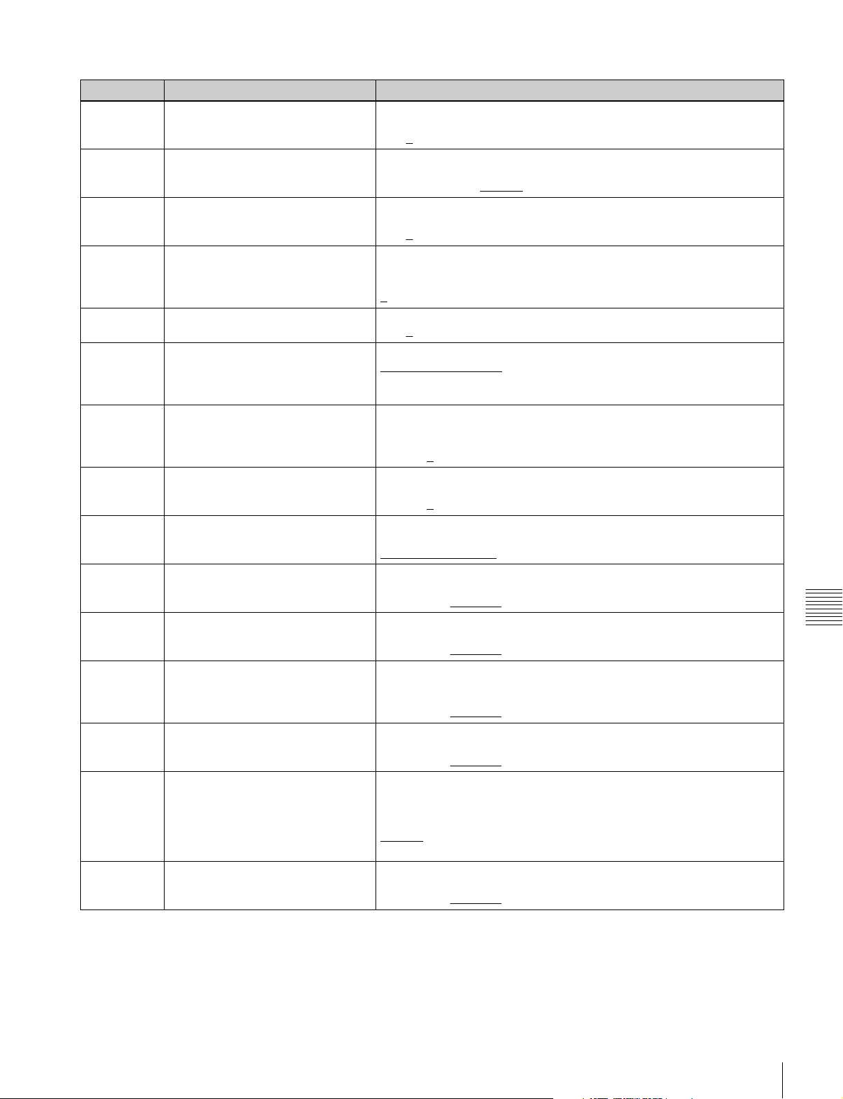
Menu items in the 900s, relating to digital process
Item number Item name Settings
938 LEVEL DEPEND THRESHOLD
939 H DETAIL FREQUENCY (DC)
(DC)
a)
a)
Adjust the down-converter image enhancer. Set the luminance range for
edge enhancement.
to FH
0 to 8
Adjust the down-converter image enhancer. Set the central frequency for
edge enhancement.
2.6MHz, 3.4MHz, 3.9MHz
940 H/V RATIO (DC)
a)
Adjust the down-converter image enhancer. Set the horizontal/vertical
ratio for edge enhancement.
to 7
0 to 3
942 V FILTER SELECT (DC)
a) c)
Set the vertical interpolation filter coefficient for down-converter output (in
1080 mode only).
If the setting value is large, the vertical resolution is high.
to 3
1
943 CROSS COLOR CRISP (DC)
950 UP CONVERTER MODE
a)
a)
Set the cross color crisp level for down-converter output.
to FH
0 to 4
Select the up-converter mode.
EDGE CROP [CROP]
LETTER BOX [L-BOX]: Select the letter box mode.
SQUEEZE [SQUEZ]: Select the squeeze mode.
951 H CROP POSITION (UC)
a)
Adjust the H-crop (the horizontal position when cropping in the edge crop
mode) of the up-converter output when menu item 950 is set to “EDGE
CROP”.
–120 to 0
952 LETTER BOX POSITION (UC)
a)
When menu item 950 is set to “LETTER BOX”, adjust the vertical position
where the picture is cut out for up-converter output in letter box mode.
–120 to 0
953 UP CONVERTER PROCESS
a)
Select the source picture to use in converting SD to HD.
FIELD: Use field pictures.
ADAPTIVE [ADAPT]
954 DETAIL GAIN (UC)
a)
Adjust the up-converter image enhancer. Adjust the sharpness of edge
enhancement.
00 (HEX) to 40 (HEX)
955 LIMITER (UC)
a)
Adjust the up-converter image enhancer. Set the maximum detail level
added to emphasize the original signal.
00 (HEX) to 20 (HEX)
956 CRISP THRESHOLD (UC)
a)
Adjust the up-converter image enhancer. Set the threshold amplitude for
emphasis (signals of amplitude lower than the threshold are not
emphasized).
00 (HEX) to 08 (HEX)
957 LEVEL DEPEND THRESHOLD
(UC)
a)
Adjust the up-converter image enhancer. Set the luminance range for
edge enhancement.
00 (HEX) to 08 (HEX)
958 H DETAIL FREQUENCY (UC)
a)
Adjust the up-converter image enhancer. Set the center frequency and
frequency properties for edge enhancement.
3.2MHz: 3.2 MHz ±1.1 MHz
4.5MHz: 4.5 MHz ±1.4 MHz
5.0MHz
4.0MHz: 4.0 MHz ±2.0 MHz
959 H/V RATIO (UC)
a)
Adjust the up-converter image enhancer. Set the horizontal/vertical ratio
for edge enhancement.
00 (HEX) to 03 (HEX)
, 4.6MHz
: Select the edge crop mode.
to 120
to 120
: Frame or field is selected automatically.
to 7F (HEX)
Chapter 7 Menus
to 3F (HEX)
to 0F (HEX)
to 0F (HEX)
: 5.0 MHz ±0.7 MHz
to 07 (HEX)
Setup Menu
89
Page 90

Menu items in the 900s, relating to digital process
Item number Item name Settings
965 IMAGE ENHANCER (INPUT UP
CONVERTER)
Sub-item pb
1
ENH SETTING
2 CONVERT Select the up-converter mode.
3 H CROP P When sub-item CONVERT is set to “CROP”, adjust the H-crop
4 L BOX P When sub-item CONVERT is set to “L-BOX”, adjust the vertical location
5 CNV PROC Select the source picture to use in converting SD to HD.
6 DETAIL Adjust the up-converter image enhancer. Set the sharpness of edge
7 LIMITER Adjust the up-converter image enhancer. Set the maximum detail level
8 CRISP Adjust the up-converter image enhancer. Set the threshold amplitude at
Chapter 7 Menus
9 DEPEND Adjust the up-converter image enhancer. Set the luminance range for
10 H DETL F Adjust the up converter image enhancer. Set the center frequency and
11 HV RATIO Adjust the up-converter image enhancer. Set the horizontal/vertical ratio
a)
Set up the operation of the up converter image enhancer for SD input,
separately from the settings for playback (menu items 950 to 959).
: While SD signals are input, make the behavior of the image
enhancer of the up-converter follow the settings for playback (menu
items 950 to 959). (Settings for sub-items 2 to 11 under menu item
965 become invalid.)
input: While SD signals are input, make the behavior of the image
enhancer of the up-converter follow the settings for sub-items 2 to 11
under menu item 965 (separate settings during input of SD signals
from those during playback).
EDGE CROP [CROP]
LETTER BOX [L-BOX]: Select the letter box mode.
SQUEEZE [SQUEZ]: Select the squeeze mode.
(horizontal crop) position for up converter output in edge crop mode.
–120 to 0
of the position where the picture is cut out for up converter output in letter
box mode.
–120 to 0
FIELD: Use field pictures.
ADAPTIVE [ADAPT]
enhancement.
00 to 40
added to emphasize the original signal.
00 to 20
which low amplitude signals are not emphasized.
00 to 08
edge enhancement.
00 to 08
frequency properties for edge enhancement.
3.2MHz: 3.2 MHz ±1.1 MHz
4.5MHz: 4.5 MHz ±1.4 MHz
5.0MHz
4.0MHz: 4.0 MHz ±2.0 MHz
for edge enhancement.
00 to 03
to 120
to 120
to 7F (hexadecimal value)
to 3F (hexadecimal value)
to 0F (hexadecimal value)
to 0F (hexadecimal value)
: 5.0 MHz ±0.7 MHz
to 07 (hexadecimal value)
: Select the edge-crop mode.
: Frame or field is selected automatically.
a) Not displayed when the unit is in 23.98P mode.
b) When the optional PDBK-202 is installed
c) Not displayed when the unit is in 720P mode.
Extended menu operations
The extended menu can be used with the same procedures
as in the basic menu.
However, since with the factory default settings the
extended menu is not displayed, it is first necessary to
enable display of the extended menu.
90
Setup Menu
To enable display of the extended menu
Proceed as follows to use the maintenance menu.
1
Holding down the PAGE/HOME button and the
SHIFT button, press the MENU button.
The maintenance menu appears on the video monitor
screen.
Page 91

2
Turn the PUSH SET knob to select “M4 SETUP
MAINTENANCE”, then press the PUSH SET knob or
the SELECT function button (F2).
The sub-items of M4: SETUP MAINTENANCE
appears.
3
Turn the PUSH SET knob to select “M40
EXTENDED MENU”, then press the PUSH SET
knob or the SELECT function button (F2).
The setting screen for M40: EXTENDED MENU
appears.
Chapter 7 Menus
4
Turn the PUSH SET knob to select “ENABLE”, and
press the SAVE function button (F5).
The message “NOW SAVING...” appears on the video
monitor screen, while the new settings are saved in
memory. When the saving operation is completed, the
video monitor screen returns to its normal indications.
When you next display the menu and change the item
display, the extended menu will appear after the basic
menu.
Setup Menu
91
Page 92
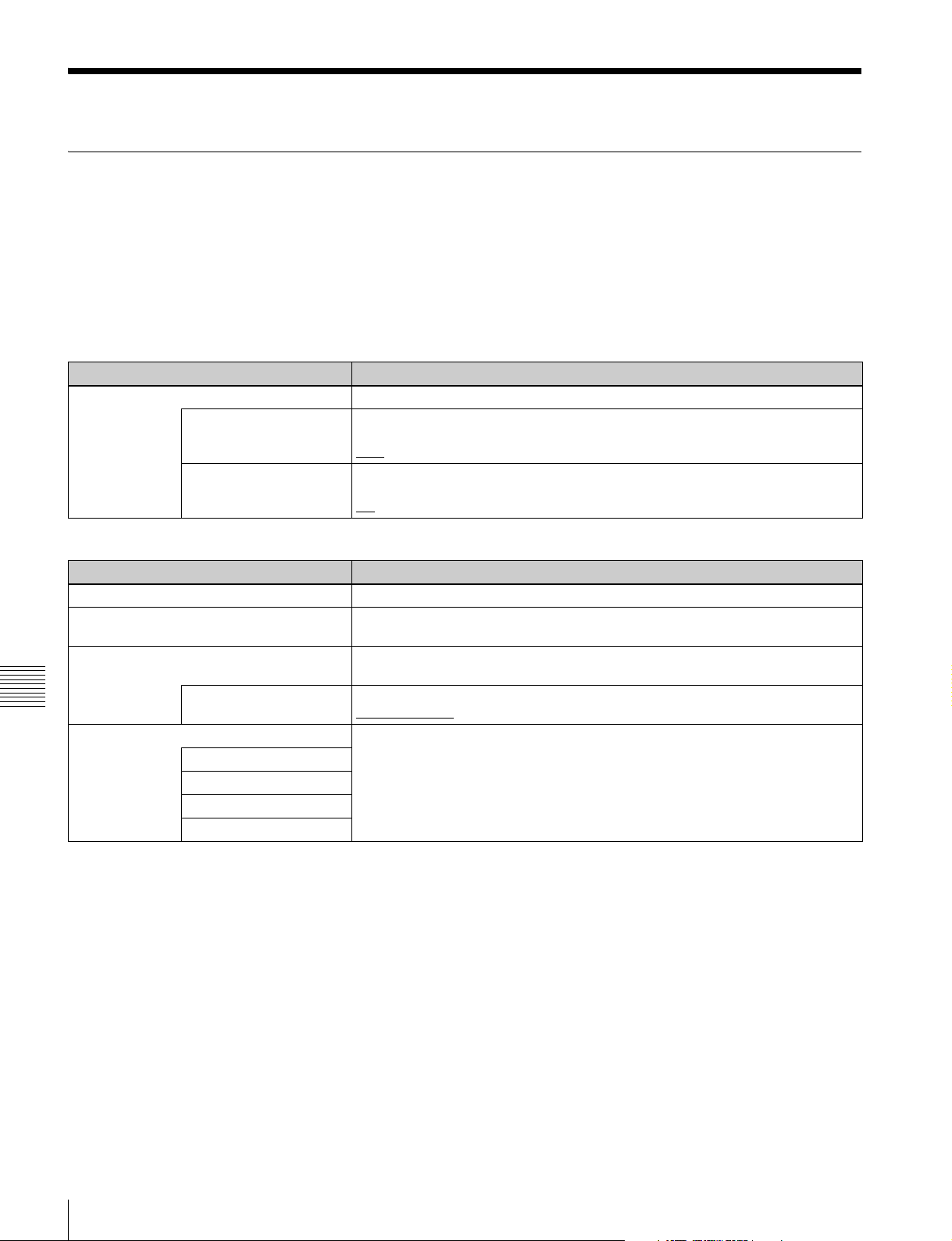
Maintenance Menu
Items in the maintenance menu
The following tables show the items in the maintenance
• The underlined values are the factory defaults.
menu.
• The values in the “Setting” column are the values that
appear in settings screens. The values in brackets [ ] are
the value shown in menu screens (when they differ from
Refer to the Maintenance Manual for information about
menu items M0: CHECK and M1: ADJUST, and about
M2: SERVICE SUPPORT settings not covered here.
the values shown in settings screens).
M2: SERVICE SUPPORT: Items related to service support
Item Setting
M22: OPTION
SETTING
Item Setting
M30: SOFTWARE VERSION Display of the software version of this unit.
M31: SERIAL NUMBER Display of the serial number and Media Access Control (MAC) address of this
M33: FILE I/F CONFIG Select the directory structure to be displayed on the side of the computer when
Chapter 7 Menus
M36: HOURS METER RESET Reset the display of resettable items of the operating hours meter.
REDUNDANT PSU Set whether to install the optional XDBK-101 and make power supply redundant.
DVB-ASI I/O Specify whether to install the optional PDBK-202.
FOLDER STYLE xdcam style [xdcam]: A structure matching with existing XDCAM devices
H11: OPE HOURS
H13: SEEK HOURS0
H14: SPDL HOURS
H15: LOAD COUNT
Set option installation states.
ON: Make redundant.
: Do not make redundant.
OFF
on: Install.
: Do not install.
off
M3: OTHERS: Other setting items
unit.
this unit is accessed through FTP/CIFS connections.
style [xds]: A structure supporting multiple media
xds
92
Maintenance Menu
Page 93

M3: OTHERS: Other setting items
Item Setting
M37: AUDIO
CONFIG
M370: HEAD ROOM Select the audio reference level (headroom).
–20dB, –18dB, –16dB, –12dB, EBUL
Note
EBUL can be selected only when the system frequency is 50i/25P.
M371: DATA LEN Select the audio channel configuration for IMX recording.
16bit x 8ch [16x8]: 16-bit, 8-channel configuration
24bit x 4ch [24x4]: 24-bit, 4-channel configuration
M372: NON-AUDIO
INPUT
Sub-item
1 Tr1/Tr2
2 Tr3/Tr4
3 Tr5/Tr6
4 Tr7/Tr8
M373: IN LEVEL Set the upper limit for the signal level input to audio channels 1/3/5/7 or 2/4/6/8.
Sub-item
1 CH1/3/5/7
2 CH2/4/6/8
M377: OUT LEVEL Set the reference level for audio output signals.
Select whether to handle digital audio signals as non-audio signals during
recording.
audio [Audio]:
data: Handle as non-audio signals.
+4dB
Note
EBUL can be selected only when the system frequency is 50i/25P.
+4dB, 0dB, –3dB, –6dB, EBUL
Handle as linear PCM audio signals.
, 0dB, –3dB, –6dB, EBUL
Note
EBUL can be selected only when the system frequency is 50i/25P.
M395: FRMT DISC Specify whether to disable the Format Disc command of the Clip Menu.
disable [dis]: Disable the Format Disc command.
enable [ena]: Enable the Format Disc command.
M396: VERIFY DISC Specify whether to make verification at the time of recording to a Professional
Disc.
: Do not make verification.
OFF
ON: Always make verification.
Chapter 7 Menus
Maintenance Menu
93
Page 94

M3: OTHERS: Other setting items
Item Setting
M3B: VANC RX
PA RA ME T ER
M3D: DATE/TIME PRESET Specifies the year, month, day, time, and time zone.
Chapter 7 Menus
M3F: FACTORY SETUP For details, refer to the Maintenance Manual.
M3B0: VANC RX
PACKET
Sub-item
1 LINE Selects the LINE for the VANC to be received.
2 DID Specification of the DID of the VANC to receive
3 SDID Specification of the SDID of the VANC to receive
M3B1: LINE1 SEL Selects the LINE to be received for the HD-SDI VANC data.
M3B2: LINE2 SEL Selects the LINE to be received for the HD-SDI VANC data.
For setting HD-SDI VANC data input parameters
Notes
• In 59.94i, 50i, 29.97P or 25P mode, selecting the line also selects the
corresponding line in the second field (for example, if line 9 is selected, line 572
is also selected for VANC packet reception).
• Menu item M3B0 enables recording of one VANC packet when the selected
line contains any packets whose DID/SDID matches the value set with this
menu item.
• Up to four packets are recorded per each line regardless of the DID and SDID
for the VANC set with menu item M3B1 or M3B2.
• It is not possible to set the same line with menu items M3B0, M3B1, and M3B2.
If the same line is specified, priority is given in the order of M3B0, M3B1, and
M3B2 (for example, if the same line is specified with M3B0 and M3B1, the
setting with M3B1 is ignored).
• When VANC data is output to HD-SDI playback signals, the number of the
output VANC line is the same as that of the input VANC line.
• When a UMID or essence mark line is selected with M3B1 or M3B2, UMID or
essence mark output takes priority. To disable UMID or essence mark output,
set setup menu item 651 or 657 to “off”.
, 9LINE to 20LINE (59.94i/50i/29.97P/25P/23.98P mode)
OFF
, 9LINE to 25LINE (59.94P/50P mode)
OFF
-FFh
00h
-FFh
00h
, 9LINE to 20LINE (59.94i/50i/29.97P/25P/23.98P mode)
OFF
OFF, 9LINE to 25LINE (59.94P/50P mode)
, 9LINE to 20LINE (59.94i/50i/29.97P/25P/23.98P mode)
OFF
, 9LINE to 25LINE (59.94P/50P mode)
OFF
M4: SETUP MAINTENANCE: Items relating to the setup menu
Item Setting
M40: EXTENDED MENU Select whether to display the extended menu.
M49: RESET ALL SETUP Reset all the menu settings to the factory settings.
M5: NETWORK: Items relating to network settings
Item Setting
M50: DHCP Set whether to assign an IP address automatically with the DHCP server.
94
Maintenance Menu
DISABLE [dis]
ENABLE [ena]: Display.
Push the SAVE function button (F5): Reset.
Push the MENU button: Return to the next highest menu level without resetting.
Notes
• The system frequency setting is also cleared. If you execute this item, reset the
system frequency (see page 28).
• Date and time settings are not cleared, but the time zone setting is cleared.
After executing this item, reset the time zone (see page 28).
DISABLE [dis]
ENABLE [ena]: Assign automatically.
: Do not display.
: Do not assign automatically.
Page 95

M5: NETWORK: Items relating to network settings
Item Setting
M51: IP ADDRESS Set the IP address of this unit.
192.168.001.010
Notes
• IP address cannot be set when DHCP is set to “ENABLE”.
• To check the automatically acquired IP address of this unit, close the maintenance
menu and then open it again.
M52: SUBNET MASK Set the subnet mask.
255.255.255.000
Notes
• Subnet mask cannot be set when DHCP is set to “ENABLE”.
• To check the automatically acquired subnet mask, close the maintenance menu
and then open it again.
M53: DEFAULT GATEWAY Set the address of the default gateway.
000.000.000.000
Notes
• The address of the default gateway cannot be set when DHCP is set to “ENABLE”.
• To check the automatically acquired address of the default gateway, close the
maintenance menu and then open it again.
M54: LINK SPEED Set the communications speed and protocol.
AUTO [auto]
: Sets automatically.
1Gbps FullDuplex [1G F]: 1 Gbps, full duplex
100Mbps FullDuplex [100 F]: 100 Mbps, full duplex
100Mbps HalfDuplex [100 H]: 100 Mbps, half duplex
10Mbps FullDuplex [10 F]: 10 Mbps, full duplex
10Mbps HalfDuplex [10 H]: 10 Mbps, half duplex
M56: JUMBO FRAME
a)
Set the size of jumbo frames.
4088, OFF(1514)
Note
This value does not include the 4 bytes of the FCS (Frame Check Sequence).
M5F: RESET NET CONFIG Reset network settings to the factory defaults.
Push the SAVE function button (F5): Reset.
Push the MENU button: Return to the next highest menu level without executing the
reset.
a) A “jumbo” frame is a frame larger than the maximum 1514 bytes (not
including FCS) of the standard Ethernet frame. Jumbo frames make it
possible to deliver larger payloads per packet. Since fewer packets need to
be routed, packet processing overhead is lower and network throughput is
potentially improved. (Note that this item is enabled only when LINK
SPEED is set to “1Gbps FullDuplex”. For it to work, all other devices that
handle packets on the network must also support jumbo frames.)
M6: DRIVE: Items relating to drive settings
Item Setting
D0: DRIVE MAINTENANCE Perform maintenance on the Professional Disc drive.
D1: SSD/HDD Specify whether to install the optional XDBK-102.
D11: RAID
on: Install.
: Do not install.
off
D13: FORMAT Format (initialize) the internal storage.
Push the SAVE function button (F5): Format (initialize).
Push the MENU button: Return to the next highest menu level without executing the
format.
Chapter 7 Menus
Maintenance Menu
95
Page 96

Maintenance menu operations
This section describes the indications in the maintenance
menu and how to change the settings.
To display the maintenance menu
Holding down the PAGE/HOME button and the SHIFT
button, press the MENU button.
The maintenance menu appears on the video monitor
screen and the currently-set menu item is displayed in
reverse video.
Meanings of indications on the menu
screen
On-screen indication Meaning
Right-pointing arrow
(c) at the right of a
menu item
Left-pointing arrow (C)
at the left of a menu
item
Character string at the
right of a menu item
An * (asterisk) in a
complete list of settings
Chapter 7 Menus
To change a menu item setting
Carry out the following operations to change the setting.
Pressing the PUSH SET knob or
the b button switches to the next
lower menu level or to a setting
selection screen.
Pressing the PUSH SET knob or
the B button switches to the
previous (higher) menu level.
Current setting of the menu item
When shown with a colon (:):
the current setting is the same
as the factory default setting.
When shown with a raised dot
(.): the current setting is
different from the factory
default setting.
Factory default setting
1
Use the PUSH SET knob or the V and v buttons to
select the required item, then press the PUSH SET
knob or the SELECT function button (F2).
The sub-items of the selected item appears.
2
Select a sub-item with the same operation as step 1,
and use the PUSH SET knob or the V and v buttons to
change the setting.
3
Press the PUSH SET knob or the SELECT function
button (F2) to confirm the setting change.
4
Press the SAVE function button (F5).
The message “NOW SAVING...” appears on the video
monitor screen, while the new settings are saved in
memory. When the saving operation is completed, the
video monitor screen returns to its normal indications.
To cancel changing a setting
Before pressing the SAVE function button (F5), press the
MENU button.
The menu disappears from the video monitor screen,
without saving the new setting.
To change network settings
To change network settings, carry out the procedure
described in the previous section, “To display the
maintenance menu”, to display the NETWORK menu
item, then carry out the following operations.
For details of the settings, consult your network
administrator.
When the IP address is assigned automatically
Note
For information about how to change network settings see
next section “To change network settings”.
MENU button
Arrow buttons
96
Function buttons
SHIFT button
PAGE/HOME button
Maintenance Menu
PUSH SET knob
Check that the network cable is connected to this unit
before carrying out the operation.
1
Set maintenance menu item M5: NETWORK
>M50: DHCP to “ENABLE”.
2
In the NETWORK menu, press the SAVE function
button (F5).
3
When the “NOW SAVING...” message vanishes,
power the unit off and then on again with the on/
standby button.
To check the assigned IP address
Select maintenance menu item M5: NETWORK
>M51: IP ADDRESS.
Page 97

Note
If the IP address cannot be assigned, this is shown as
“000.000.000.000.” In this case, consult the network
administrator.
Contact your network administrator if you have any
questions about the proper settings for these items.
1
Select maintenance menu item M5: NETWORK
>M54: LINK SPEED.
To set the IP address
First set DHCP to “DISABLE” (see the previous section,
“When the IP address is assigned automatically”).
1
Select maintenance menu item M5: NETWORK
>M51: IP ADDRESS.
2
Press the PUSH SET knob.
The IP address appears, and the digit that can be
changed flashes.
3
Set the IP address.
To select a different digit to be changed
Use the B and b buttons.
To change the value of a digit
Turn the PUSH SET knob.
Turning clockwise increases the value, and turning
counterclockwise decreases the value.
The V and v buttons can also be used.
To return to the factory default setting
Press the RESET button.
2
Press the PUSH SET knob.
Combinations of the communications speed and
protocol (1Gbps FullDuplex, 100Mbps FullDuplex,
100Mbps HalfDuplex, 10Mbps FullDuplex, 10Mbps
HalfDuplex) appear, and the arrow flashes.
3
Press the PUSH SET knob or use the V or v button to
select a combination of communications speed and
protocol.
To return to the factory default setting
Press the RESET button.
4
Press the SAVE function button (F5).
This returns to the NETWORK menu.
5
In the NETWORK menu, press the SAVE function
button (F5).
6
When the message “NETWORK CONFIG WAS
CHANGED. PLEASE REPOWER.” appears, power
the unit off and then on again with the on/standby
button.
4
When all digits are set, press the SAVE function
button (F5).
This returns to the NETWORK menu.
5
Repeat steps 1 to 4 as required, to set the subnet mask
and default gateway.
6
In the NETWORK menu, press the SAVE function
button (F5).
7
When the message “NETWORK CONFIG WAS
CHANGED. PLEASE REPOWER.” appears, power
the unit off and then on again with the on/standby
button.
To set the communications speed and
protocol
Set the communications speed and protocol (LINK
SPEED) to match the network environment.
To set the communications speed and protocol, proceed as
explained in the previous section “To display the
maintenance menu” to display the NETWORK menu and
then proceed as follows.
Chapter 7 Menus
Maintenance Menu
97
Page 98

Appendix
Important Notes on Operation
Use and storage
Do not subject the unit to severe shocks
The internal mechanism may be damaged or the body
warped. Shocks may also damage the internal storage.
Do not cover the unit while operating
Doing so will cause temperatures to rise inside the unit,
possibly resulting in failure.
After use
Turn off the on/standby button.
If you plan not to use the unit for a long time, turn off the
main power switch on the rear panel as well.
• In excessive heat or cold (operating temperature range:
5°C to 40°C (41°F to 104°F))
Remember that in summer or in warm climates the
temperature inside a car with the windows closed can
easily exceed 50°C (122°F).
• In damp or dusty locations
• Locations where the unit may be exposed to rain
• Locations subject to violent vibration
• Near strong magnetic fields
• Close to radio or TV transmitters producing strong
electromagnetic fields.
• In direct sunlight or close to heaters for extended periods
To prevent electromagnetic interference from
portable communications devices
The use of portable telephones and other communications
devices near this unit can result in malfunctions and
interference with audio and video signals.
It is recommended that the portable communications
devices near this unit be powered off.
Shipping
• To prevent damage to the internal storage, always power
the unit off.
• Remove memory cards before transporting the unit.
• If sending the unit by truck, ship, air or other
Appendix
transportation service, pack it in the shipping carton of
the unit.
Care of the unit
If the body of the unit is dirty, clean it with a soft, dry cloth.
In extreme cases, use a cloth steeped in a little neutral
detergent, then wipe dry. Do not use organic solvents such
as alcohol or thinners, as these may cause discoloration or
other damage to the finish of the unit.
In the event of operating problems
If you should experience problems with the unit, contact
your Sony service or sales representative.
Use and storage locations
Store in a level, ventilated place. Avoid using or storing the
unit in the following places.
About the LCD panel
The LCD panel fitted to this unit is manufactured with high
precision technology, giving a functioning pixel ratio of at
least 99.99%. Thus a very small proportion of pixels
maybe “stuck”, either always off (black), always on (red,
green, or blue), or flashing. In addition, over a long period
of use, because of the physical characteristics of the liquid
crystal display, such “stuck” pixels may appear
spontaneously. These problems are not a malfunction.
Note that any such problems have no effect on recorded
data.
Condensation
If you move the unit from a very cold place to a warm
place, or use it in a damp location, condensation may form
on the optical pickup.
Then, if the unit is operated in this state, recording and
playback may not be performed properly.
98
Important Notes on Operation
Page 99

When you move or operate the unit in an environment
where condensation may form, be sure to insert a disc in
advance.
Precautions for products with builtin HDD
PD1000
This unit has a built-in hard disk drive (HDD). The HDD
is a precision device. If subject to shock, vibration, static
electricity, high temperature or humidity, data corruption
can occur. When installing and using the unit, closely
observe the following precautions.
Protect from shocks and vibrations
When subject to shocks or vibrations, the HDD can be
damaged and corruption of data on the HDD can occur.
• When transporting the unit, use the specified packing
material. When transporting on a dolly or similar, use a
type which does not transmit excessive vibrations.
Excessive shocks and vibrations can damage the HDD.
• Never move the unit while it is powered.
• Protect all HDD-equipped devices in the rack from
shocks.
• Before removing or inserting the unit in a rack, make
sure that power to any other HDD-equipped devices in
the rack is also switched OFF.
• Place the unit on a level and stable location.
• Do not place the unit near other devices that may become
a source of vibrations.
Temperature and humidity related
precautions
Use and store the unit only in locations where the specified
temperature and humidity ranges are not exceeded. Also,
do not power the unit on while its outer case is removed.
Temperature range for operation: +5 to +40ºC (+41 to
+104ºF)
Humidity range for operation: 20 to 90% relative
humidity (no condensation)
Temperature range for storage: –20 to +60ºC (–4 to
+140ºF)
When HDD seems to be faulty
Even if the HDD is showing signs of malfunction, be sure
to observe all the above precautions. This will prevent
further damage from occurring until the problem can be
diagnosed and corrected.
HDD replacement
Contact your Sony service or sales representative about
periodic replacement of the HDD.
Do not expose to static electricity
Remove any plastic items that can produce static
electricity (bubble wrap, etc.) from the work area. Also,
when handling the HDD, make sure to wear a grounded
antistatic strap.
Wait for 30 seconds after turning the
power off
For a brief interval after the power is turned off, the platters
inside the HDD will still keep spinning and the heads will
be in an insecure position. During this interval, the unit is
more susceptible to shocks and vibrations than during
normal operation. For a period of at least 30 seconds after
turning the power off, avoid subjecting the unit even to
very light shocks. After this period, the hard disk will be
fully stopped and the unit can be manipulated.
Appendix
Important Notes on Operation
99
Page 100

Periodic Maintenance
To display the operating hours meter
Press the MENU button to display the setup menu, then
turn the PUSH SET knob to display the required item (H11
to H15).
Operating hours meter
The operating hours meter can provide six items of
information about the operational history of the unit. The
information can be displayed in the status display area and
also, by text superimposition, on the video monitor screen
or PC monitor connected to the MONITOR connector. Use
the information as a guide in scheduling periodic
maintenance.
For periodic maintenance, contact your Sony service or
sales representative.
Display modes of the operating hours
meter
H01: OPERATION HOURS mode
Displays the total number of hours the unit has been
powered on in units of 1 hour.
H02: LASER PARAMETER 0 mode (not
resettable)
Of the two optical heads, this shows a counter of the
cumulative light output time by one optical head in units of
1)
hours.
to replace the optical head.
This can be used as a guide in determining when
To reset the display of the operating hours
meter
Select the item you want to reset with the menu item M36:
HOURS METER RESET, and press the PUSH SET knob.
To exit from the operating hours meter
Press the RETURN function button (F1) to return to the
setup menu.
Press the EXIT function button (F6) to return to the screen
that was displayed before you entered the setup menu.
1) The counter advances at different rates during recording and playback. It
is also affected by the ambient temperature.
H11: OPERATION HOURS mode (resettable)
Same as H01 except that the count is resettable.
This can be used as a guide in determining when to replace
parts.
H13: SEEK RUNNING HOURS 0 mode (resettable)
Appendix
Of the two optical heads, this shows the cumulative seek
operation time for one optical head in units of hours.
The count is resettable.
This can be used as a guide in determining when to replace
the seek motor.
H14: SPINDLE RUNNING HOURS mode
(resettable)
This shows the cumulative spindle rotation time, in units of
hours.
The count is resettable.
This can be used as a guide in determining when to replace
the spindle motor.
H15: LOADING COUNTER mode (resettable)
Display the total number of times disc has been loaded in
the unit.
The count is resettable.
100
Periodic Maintenance
 Loading...