

Sony XDRF-1-HD Service manual
XDR-F1HD
SERVICE MANUAL
Ver. 1.0 2008.01
HD Radio Broadcasting was approved by the Federal
Communications Commission in October 2002 as the system for digital
AM and FM broadcasting in the U.S.
HD Radio technology features include:
– Static-free, clear radio reception.
– FM Multicasting – the ability to broadcast multiple program streams over
a single FM frequency.
– A variety of “data services,” including text-based
information – artist name, song title, etc. scrolled across your
receiver display.
– Digital broadcasts in the same frequencies as analog
broadcasts; listeners do not need to learn a new station
number and today’s stations remain at their current place on the dial.
HD Radio technology is developed and licensed by iBiquity Digital Corporation and supported by the leaders of the
broadcasting, consumer electronics and automotive industries.
HD Radio
tal Corp. U.S. and Foreign Patents. HD Radio
proprietary trademarks of iBiquity Digital Corp.
TM
T echnology Manufactured Under License From iBiquity Digi-
TM
and the HD Radio logo are
US Model
SPECIFICATIONS
Time display 12-hour system
Frequency range FM: 87.5 – 108 MHz
AM: 530 – 1,710 kHz
Audio output Output level 0.7 Vrms at 47 kΩ
Recommended load impedance over 10 kΩ
Antenna terminal 75 Ω antenna terminal for FM
Antenna terminal for AM
Power requirements 120 V AC, 60 Hz
Dimensions Approx. 180 × 60 × 160 mm (w/h/d)
(7
parts and controls
Mass Approx. 1.1 kg (2 lb 6.8 oz)
Supplied accessories Remote commander (1)
FM dipole antenna (1)
AM loop antenna (1)
Design and specifi cations are subject to change
without notice.
1
/8 × 2 3/8 × 6 3/8 inches) not incl. projecting
9-887-972-01
2008A04-1
2008.01
©
FM/AM DIGITAL TUNER
Sony Corporation
Audio Business Group
Published by Sony Techno Create Corporation

XDR-F1HD
SAFETY CHECK-OUT
After correcting the original service problem, perform the following safety check before releasing the set to the customer:
Check the antenna terminals, metal trim, “metallized” knobs,
screws, and all other exposed metal parts for AC leakage.
Check leakage as described below.
LEAKAGE TEST
The AC leakage from any exposed metal part to earth ground and
from all exposed metal parts to any exposed metal part having a
return to chassis, must not exceed 0.5 mA (500 microamperes.).
Leakage current can be measured by any one of three methods.
1. A commercial leakage tester, such as the Simpson 229 or RCA
WT-540A. Follow the manufacturers’ instructions to use these
instruments.
2. A battery-operated AC milliammeter. The Data Precision 245
digital multimeter is suitable for this job.
3. Measuring the voltage drop across a resistor by means of a
VOM or battery-operated AC voltmeter . The “limit” indication
is 0.75 V, so analog meters must have an accurate low-voltage
scale. The Simpson 250 and Sanwa SH-63Trd are examples
of a passive VOM that is suitable. Nearly all battery operated
digital multimeters that have a 2 V AC range are suitable. (See
Fig. A)
To Exposed Metal
Parts on Set
Notes on chip component replacement
• Never reuse a disconnected chip component.
• Notice that the minus side of a tantalum capacitor may be damaged by heat.
UNLEADED SOLDER
Boards requiring use of unleaded solder are printed with the leadfree mark (LF) indicating the solder contains no lead.
(Caution: Some printed circuit boards may not come printed with
the lead free mark due to their particular size)
: LEAD FREE MARK
Unleaded solder has the following characteristics.
• Unleaded solder melts at a temperature about 40 °C higher
than ordinary solder.
Ordinary soldering irons can be used but the iron tip has to be
applied to the solder joint for a slightly longer time.
Soldering irons using a temperature regulator should be set to
about 350 °C.
Caution: The printed pattern (copper foil) may peel away if the
heated tip is applied for too long, so be careful!
• Strong viscosity
Unleaded solder is more viscous (sticky, less prone to fl ow)
than ordinary solder so use caution not to let solder bridges
occur such as on IC pins, etc.
• Usable with ordinary solder
It is best to use only unleaded solder but unleaded solder may
also be added to ordinary solder.
AC
1.5 kΩ0.15 μF
Earth Ground
voltmeter
(0.75 V)
Fig. A. Using an AC voltmeter to check AC leakage.
TABLE OF CONTENTS
1. GENERAL .................................................................. 3
2. DISASSEMBLY
2-1. Cabinet Upper Assy ....................................................... 6
2-2. KEY Board ...................................................................... 7
2-3. MICON Board Assy ........................................................ 7
2-4. MAIN Board ................................................................... 8
2-5. POWER Board ................................................................ 8
3. DIAGRAMS
3-1. Block Diagram ................................................................ 11
3-2. Printed Wiring Board –Main Section– ............................ 12
3-3. Printed Wiring Board –Power Section– .......................... 13
3-4. Schematic Diagram –Main/Power Section– ................... 14
3-5. Printed Wiring Board –Micon Section– .......................... 15
3-6. Schematic Diagram –Micon Section– ............................ 16
4. EXPLODED VIEWS
4-1. Cabinet Upper Section .................................................... 20
4-2. Cabinet Lower Section .................................................... 21
4-3. MICON Board Section ................................................... 22
5. ELECTRICAL PARTS LIST .............................. 23
SAFETY-RELATED COMPONET WARNING!
COMPONENTS IDENTIFIED BY MARK 0 OR DOTTED LINE
WITH MARK 0 ON THE SCHEMATIC DIAGRAMS AND IN
THE PARTS LIST ARE CRITICAL TO SAFE OPERATION.
REPLACE THESE COMPONENTS WITH SONY PARTS
WHOSE PART NUMBERS APPEAR AS SHOWN IN THIS
MANUAL OR IN SUPPLEMENTS PUBLISHED BY SONY.
2
SECTION 1
GENERAL
XDR-F1HD
This section is extracted
from instruction manual.
A
DISPLAY
?/1
BAND
SCAN
L
R
AUDIO OUT
AM FM
HD SCAN
RESET
SLEEP
MENU ENTERTUNETUNE
AM
SELECT
ANTENNA
FM
AC power cord
PRESET PRESET
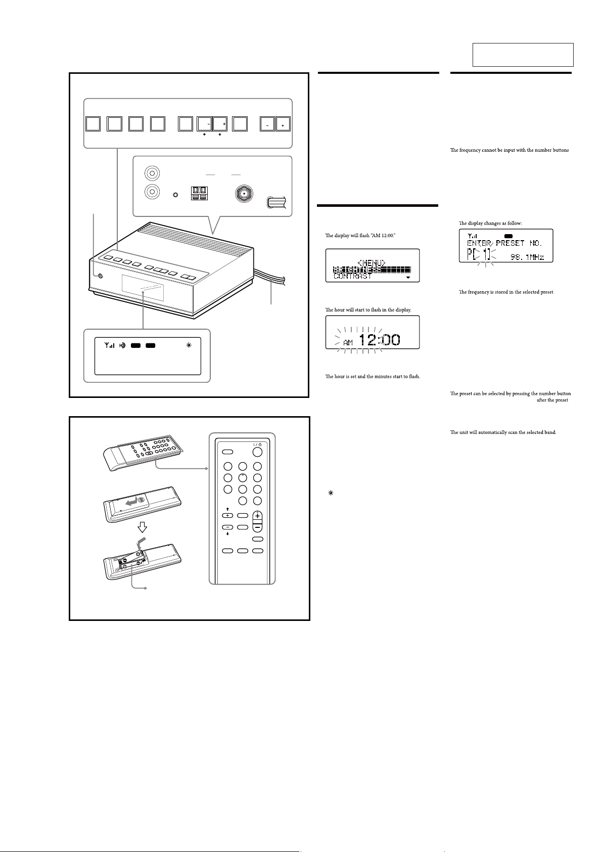
Preparing the remote
commander
Installing the batteries into the remote commander (See Fig. B)
Insert two size AAA (R03) batteries (not supplied).
When to replace the batteries
With normal use, the batteries should last for about
six months. When the remote commander no longer
operates the unit, replace all the batteries with new ones.
Notes
• Do not charge dry batteries.
• When you are not going to use the remote commander
for a long time, remove the batteries to avoid any
damage caused by leakage and corrosion.
Setting the clock
1 Plug in the unit.
2 Press MENU to show the menu display.
3 Press SELECT M or m to select “TIME SET,”
then press ENTER.
4 Press SELECT M or m until current hour
appears in the display, then press ENTER.
5 Repeat step 4 to set the minute.
Note
If you do not set the menu within 65 seconds, the setting
mode is canceled.
Playing the radio
–Manual tuning
1 Press ?/1 to turn on the radio.
2 Press BAND to select the band AM or FM.
3 Press TUNE + or – to tune in to a desired
frequency.
Note
of the remote commander.
–Preset tuning
You can preset 20 stations each for AM and FM.
Presetting a station
1 Follow s teps 1 to 3 in “Manual tuning” to tune
the frequency you wish to preset.
2 Press and hold ENTER for a few seconds.
FM
3 Press PRESET + or – to select the preset
number, then press ENTER.
number.
To preset another station, repeat these steps.
Note
If you try to store another station in the same preset
number, the previously stored station will be replaced.
Tuning in to a station
1 Press ?/1 to turn on the radio.
2 Press BAND to select the band AM or FM.
3 Press PRESET + or – to select the desired
preset number.
Tip
of the remote commander. Press ENTER
number is selected.
B
Size AAA (R03)
× 2
SLEEP
123
456
7809
ENTER
PRESET
HD SCAN
TUNE/
SELECT
SCAN
BAND
BRIGHTMENU
DISPLAY
The number 5 and the PRESET +
buttons have a tactile dot.
To change the display to the
daylight saving time (summer
time) indication
1 Press MENU to show the menu display.
2 Press SELECT M or m to select “DST,” then
press ENTER.
3 Press SELECT M or m to select “ON,” then
press ENTER.
“ ” appears and the time indication changes to
summer time.
To deactivate the DST function, select “OFF” in step 3.
–Scan tuning
In HD scan, HD Radio stations are scanned.
1 Press ?/1 to turn on the radio.
2 Press BAND to select the band AM or FM.
3 Press SCAN or HD SCAN on the unit or
remote commander.
Scanning of the selected band starts.
When a station is received, scanning pauses for 3
seconds and then continues.
4 When the unit tunes in to the desired station,
do any of the following operations to stop
scanning.
–Press ENTER on the unit or remote commander.
–Press
SCAN or HD SCAN.
5 If necessary, press TUNE + or – to tune in to
the station more precisely.
3

XDR-F1HD
Changing the display
mode and settings
To change the display mode
Press DISPLAY.
When an analog radio station is received
FM
When an HD Radio station is received
FM
x
FM
Setting the sleep timer
You can enjoy falling asleep to the radio using the built-
a preset duration.
1 Press SLEEP on the remote commander.
“SLEEP” and the digits for the sleep timer duration
appear.
SLEEP
FM
x
FM
A Field strength level indicator
B Preset number*
C Band
D Frequency
E Current time
* When you tune in a station by selecting a preset
number.
When an analog FM broadcast that supports RBDS
(Radio Broadcast Data System) is received
FM
x
FM
x
x
FM
A HD indicator
HD indicator Reception status
Stays lit
Flashes
Not displayed
*
then stays lit.
B Field strength level indicator
C Preset number*
D Call sign
E Band
F Song title/artist name
G Channel number (FM only)
Appears when HD Radio broadcasts multiple
program.
Press TUNE + or – to select a sub channel.
H Frequency
I Current time
J Station name
K Text information
* When you tune in a station by selecting a preset
number
Note
broadcast or the station.
Strong HD signal, digital reception*
Weak HD signal, analog reception
No HD signal, analog reception
If you press SLEEP
unit is turned on.
2 Press SLEEP repeatedly to select the desired
sleep timer setting.
Each press changes the setting time as follows:
60 45 1530 OFF
when the duration time is set.
is passed.
To change the sleep timer setting
You can press SLEEP repeatedly to select the desired
activated.
To deactivate the sleep timer
Press ?/1
elapsed, or press SLEEP repeatedly to set the sleep timer
to “SLEEP OFF” in step 2.
Note
remote commander.
Resetting the unit
Press this button with a pointed object if the radio fails
have preset, etc., will revert to the factory preset.
FM
A Field strength level indicator
B Preset number*
C Band
D Station name
Name of station currently tuned in.
E Frequency
F Current time
G Text information
Text information transmitted from station.
* When you tune in a station by selecting a preset
number.
Note
broadcast or the station.
To change the display settings
(BRIGHTNESS/CONTRAST)
1 Press MENU to show the menu display.
2 Press SELECT M or m to select
“BRIGHTNESS” or “CONTRAST,” then press
ENTER.
3 Press SELECT M or m to select the setting or to
adjust the level, then press ENTER.
BRIGHTNESS:
“HIGH,” “MIDDLE” or “LOW.”
CONTR AST:
11 levels.
Note
If you do not set the menu within 10 seconds, the setting
Tip
You can adjust “BRIGHTNESS” directly by pressing
BRIGHT on the remote commander.
Using the remote
commander
Buttons shared on both the remote commander and the
unit control the same functions.
HD SCAN button
stations are received for 3 seconds in order of frequency.
SCAN button
stations are received for 3 seconds in order of frequency.
BRIGHT button
To adjust the brightness of the display.
4
XDR-F1HD
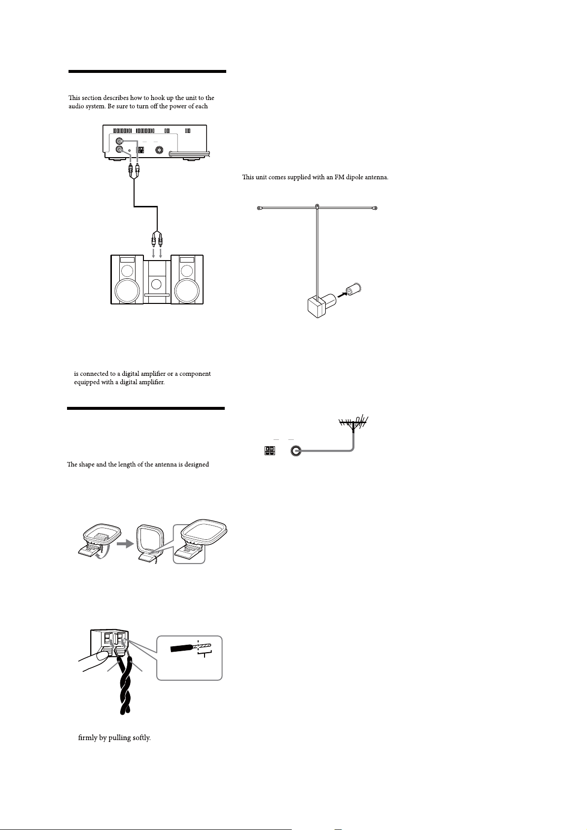
Connecting the system
component before making the connections.
L
R
AUDIO OUT
AUDIO OUT
(Stereo pin plug)
(Red) (R)
Audio input
(White) (L)
Notes
• Install this system so that the power cord can be
unplugged from the wall socket immediately in the
event of trouble.
• If noise occurs, separate the unit from other
components.
• Noise may occur during AM reception if the unit
ANTENNA
AM
RESET
FM
AUDIO OUT
(Stereo pin plug)
(White) (L)
Audio cable (Not supplied)
Audio input
(Red) (R)
Connecting the antenna
Adjusting the AM loop antenna
Find a place and an orientation that provide good
reception.
• Do not place the AM loop antenna near the unit or
other AV equipment, as noise may result.
Tip
Adjust the direction of the AM loop antenna for best AM
broadcast sound.
To connect the FM antenna
Connect an antenna that provides good reception to the
FM antenna terminal.
FM dipole antenna
(supplied)
Adjusting the FM dipole antenna
Be sure to fully extend the FM dipole antenna. Attach the
antenna in the shape of a T to a high position on a wall
away from this unit.
Tip
If you have poor FM reception, use a 75 Ω coaxial cable
(not supplied) to connect the unit to an outdoor FM
antenna as shown below.
To connect the AM loop
antenna
to receive AM signals. Do not dismantle or roll up the
antenna.
1 Remove only the loop part from the plastic
stand.
2 Set up the AM loop antenna.
3 Connect the cords to the AM antenna
terminals.
Cord (A) or cord (B) can be connected to either
terminal.
Insert the cord while
pushing down the
terminal clamp.
Only inser
AB
to here.
t up
ANTENNA
AM FM
Outdoor FM antenna
4 Make sure the AM loop antenna is connected
5
XDR-F1HD
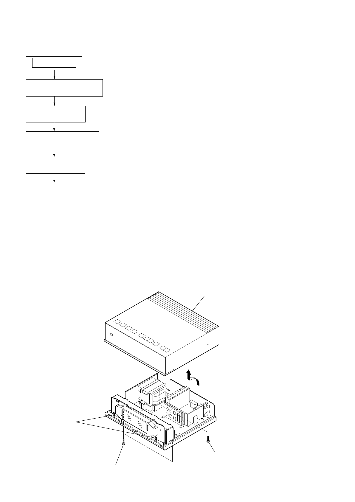
SECTION 2
DISASSEMBLY
Note: This set can be disassemble according to the following sequence.
SET
2-1. CABINET UPPER ASSY
(Page 6)
2-2. KEY BOARD
(Page 7)
2-3. MICON BOARD ASSY
(Page 7)
2-4. MAIN BOARD
(Page 8)
2-5. POWER BOARD
(Page 8)
Note: Follow the disassembly procedure in the numerical order given.
2-1. CABINET UPPER ASSY
cabinet upper assy
two claws
two (+) P tapping screws
(B 2.6)
three (+) P tapping screws
(B 2.6)
6

2-2. KEY BOARD
XDR-F1HD
Remove the three solders.
three screws
red
2-3. MICON BOARD ASSY
KEY board
two screws
MICON board assy
red
Remove the eleven solders.
red
7
XDR-F1HD
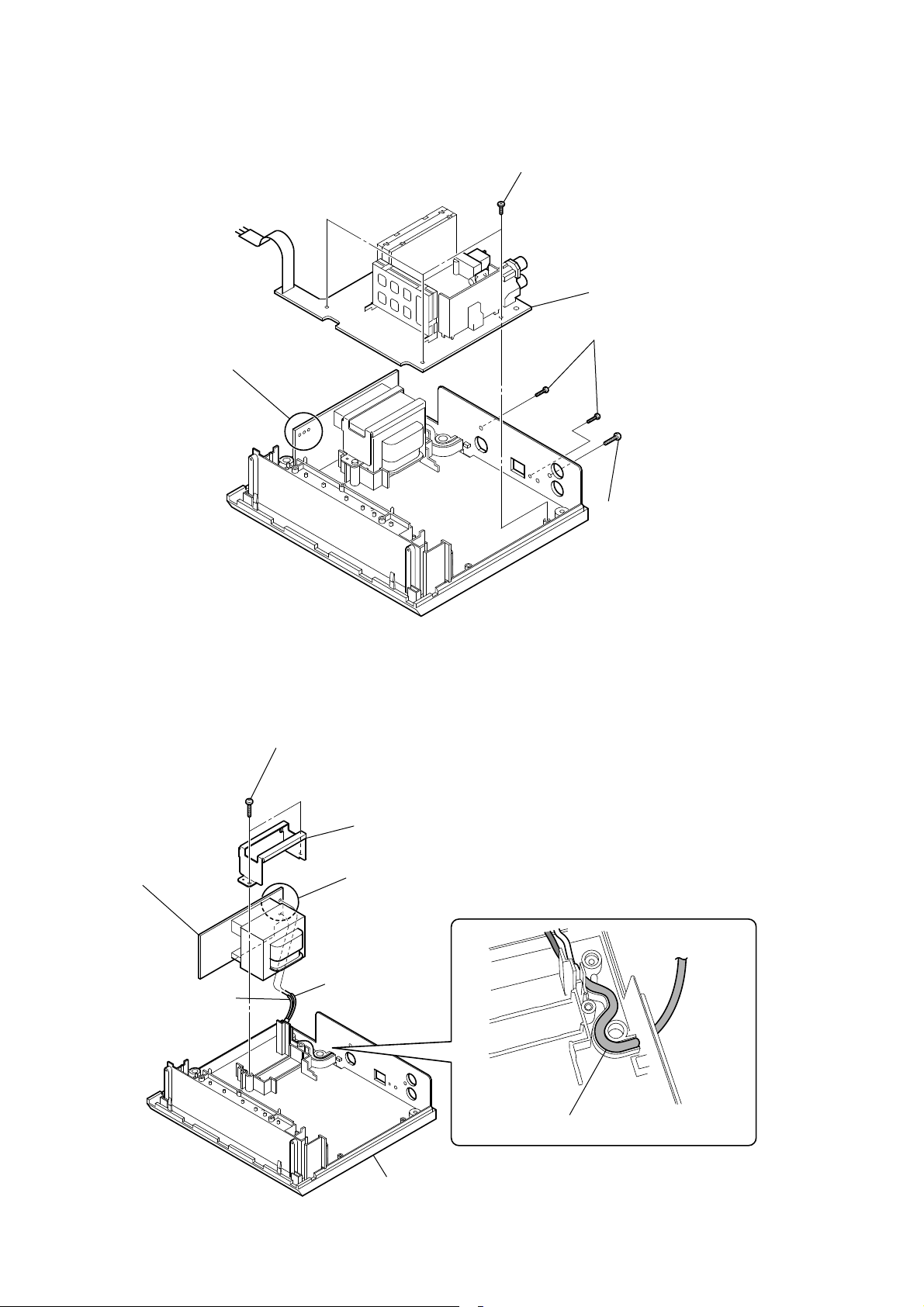
2-4. MAIN BOARD
Remove the three solders.
three screws
MAIN board
two (+) P tapping screws
(B 2.6)
2-5. POWER BOARD
POWER board
(+) BV tapping screws
(B 3)
two (+) P tapping screws
(B 2.6)
retainer plate (trans)
Remove the two solders.
black
white
When assembling the set, route the power cord
as shown below and install it.
cabinet (lower)
8

MEMO
XDR-F1HD
9
 Loading...