

Sony XC-ST70,XC-ST70CE User Manual
CCD B/W VIDEO
CAMERA MODULE
XC-ST70/70CE
User’s
G
uide
(Ver. 1.0)
—
English
—

XC-ST70/70CE
Table of Contents
OUTLINE ................................................................................................................. 1
MAIN FEATURES.................................................................................................... 1
SYSTEM CONFIGURATION ................................................................................... 2
MAIN SPECIFICATIONS ......................................................................................... 3
CONNECTION DIAGRAM....................................................................................... 4
LOCATION OF PARTS AND OPERATION ............................................................. 5
PHASE CONDITIONS OF EXTERNAL SYNCHRONIZATION................................ 6
ELECTRONIC SHUTTER........................................................................................ 7
RESTART RESET (R.R)........................................................................................ 10
FRAME IMAGE OUTPUT WITH STROBE LIGHT ................................................ 12
OUTPUT WA VEFORM TIMING CHART ............................................................... 13
TIMING CHART OF EXTERNAL TRIGGER SHUTTER - MODE 1....................... 17
TIMING CHART OF EXTERNAL TRIGGER SHUTTER - MODE 2....................... 23
DIMENSIONS........................................................................................................ 25
SPECTRAL SENSITIVITY CHARACTERISTICS (TYPICAL VALUE)................... 26
VARIOUS LENS SELECTION............................................................................... 27

1
XC-ST70/70CE
OUTLINE
The XC-ST70/70CE is a compact, lightweight black-and-white camera module using the latest technology and a 2/3inch new-generation CCD. Each mode can be set by selecting the switches on the rear panel. The XC-ST70/70CE
provides an external trigger shutter that can catch a high-speed moving subject using an external signal. This enables
a still image to be read in arbitrary timing. The XC-ST70/70CE meets the high-le v el needs of image inspection based
on a high-definition image utilizing a 2/3-inch CCD that is popular in the image processing field.
In addition, the XC-ST70/70CE incorporates significant shock and vibration resistance allowing it to be easily
incorporated into machine vision equipment.
MAIN FEATURES
2/3" IT CCD
External trigger shutter function
(XC-ST70: 1/4 to 1/10,000 seconds, XC-ST70CE: 1/4 to 1/8,000 seconds)
Inputting the trigger pulse gives one still image. This feature allows the capture of high-speed moving object.
Restart Reset (R.R) function
Inputting HD and VD signals (2 VD or more) continuously from the outside can catch one image at arbitrary time
and control the stored CCD.
This function is used for long exposures and strobe with frame image output.
Synchronization system: Internal/external HD/VD, and VS
(VS is used only during external synchronization.)
Inputting an HD/VD signal from the outside automatically establishes external synchronization.
This function is effective for controlling multiple cameras efficiently from the external system.
All control switches on outside of camera.
Setting each mode on rear panel:
The setting of each mode can be changed by selecting DIP
Almost all switches are located on the rear panel. This feature permits easy setting after equipment is installed.
Compact and lightweight
C-mount
Excellent shock and vibration resistance
2
XC-ST70/70CE
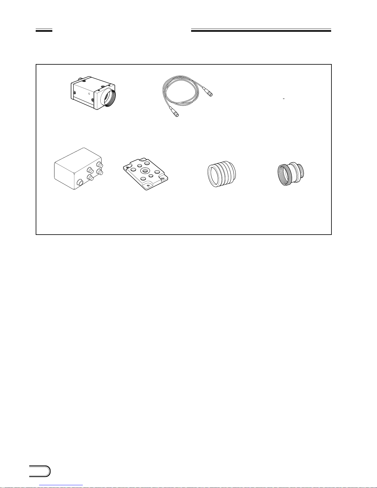
SYSTEM CONFIGURATION
The components making up the system based on XC-ST70/ST70CE video camera are as follows.
Tripod adaptor
VCT-ST70I (Isolated type)
Close-up ring kit
LO-77ERK
C-mount lenses
VCL-50Y-M
VCL-25Y-M
VCL-16Y-M
VCL-12YM
VCL-08YM
Junction box
JB-77
Video camera module
XC-ST70/70CE
Camera adaptor
DC-700/700CE
Camera cables
CCXC-12P02N (2 m)
CCXC-12P05N (5 m)
CCXC-12P10N (10 m)
CCXC-12P25N (25 m)
3
XC-ST70/70CE
MAIN SPECIFICATIONS
Image pickup device: 2/3-inch interline transfer CCD
Number of effective pixels
XC-ST70: 768(H) x 494(V)
XC-ST70CE: 752(H) x 582(V)
CCD horizontal driving frequency
XC-ST70: 14.318 MHz
XC-ST70CE: 14.187 MHz
CCD vertical driving frequency
XC-ST70: 15.734 kHz
XC-ST70CE: 15.625 kHz
Signal system EIA/CCIR
Cell size
XC-ST70: 11.6(H) x 13.5(V) um
XC-ST70CE: 11.6(H) x 11.2(V) um
Lens mount C-mount
Flange back 17.526 mm
Synchronization system
Internal/external
(Selected automatically.)
External sync input/output
HD/VD (2 to 5 Vp-p)
VS (Sync level: 0.3 Vp-p
+0.3 V
)
–0.15 V
*
Automatically selected according
to the existence of an input signal
when the selection switch on the
rear panel is set to EXT.
Allowable frequency deviation of external synchronization
± 1 %
(in horizontal synchronous frequency)
Jitter Within ± 50 nsec
Scanning system 2:1 interlacing
Non-interlacing
(during external sync input)
Horizontal resolution
XC-ST70: 570 TV lines
XC-ST70CE: 560 TV lines
Sensitivity 400 lx F8 (γ = ON, 0 dB)
S/N ratio
XC-ST70: 60 dB
XC-ST70CE: 58 dB
Minimum subject illuminance
0.3 lx (F1.4, AGC ON)
Gain AGC/Manual/Fixed
(Can be selected using the switch
on the rear panel.)
Gamma correction ON/OFF
(Can be selected using the switch
on the rear panel.)
Electronic shutter
XC-ST70: 1/100 to 1/10,000 seconds
XC-ST70CE: 1/120 to 1/10,000 seconds
External trigger shutter
XC-ST70: 1/4 to 1/10,000 seconds
XC-ST70CE: 1/4 to 1/8,000 seconds
*
Set using the DIP switch on the rear panel, or
continuously variable with the trigger pulse
width.
Supply voltage +12 VDC (±10%)
Power consumption 2.1 W
Operating temperature
–5 ˚C to +45 ˚C
Storage temperature –30 ˚C to +60 ˚C
Performance assurance temperature
0 ˚C to +40 ˚C
Operating humidity 20 to 80 % (Non-condensing)
Storage humidity 20 to 95 % (Non-condensing)
Vibration resistance 10G
(For 20 minutes in the X, Y, and Z
directions at 20 to 200 Hz)
Shock resistance 70G
Outside dimensions 44(W) x 29(H) x 57.5(D) mm
Weight 105 g
Standards UL1492, FCC Class A Digital
Device, and CE (EN50081-2 +
EN50082-2)
Other
Restart Reset function
frame or
field integration can be selected.
Conforms to new 12-pin EIAJ.
Accessories Lens mount cap (1)
Instruction Manual (1)
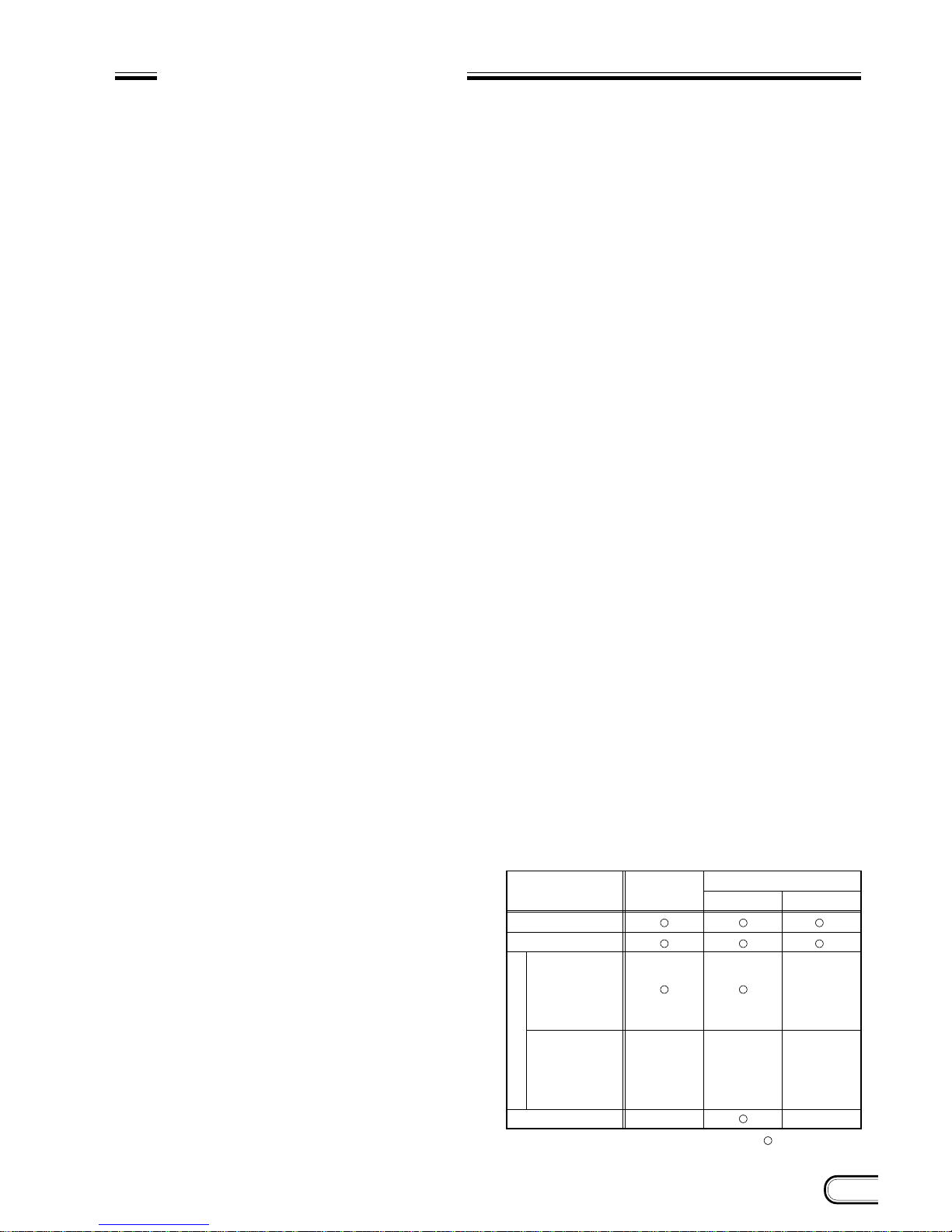
External synchronization for each mode
Mode
Normal
Normal shutter
Restart Reset
Mode 1
non-reset
External trigger shutter
Mode 2
reset
Trigger signal
generates an
internal VD
(single) signal.
Internal sync
External sync
HD/VD
×
: Can be used.
×
: Cannot be used.
VS
×
×
×
×
4
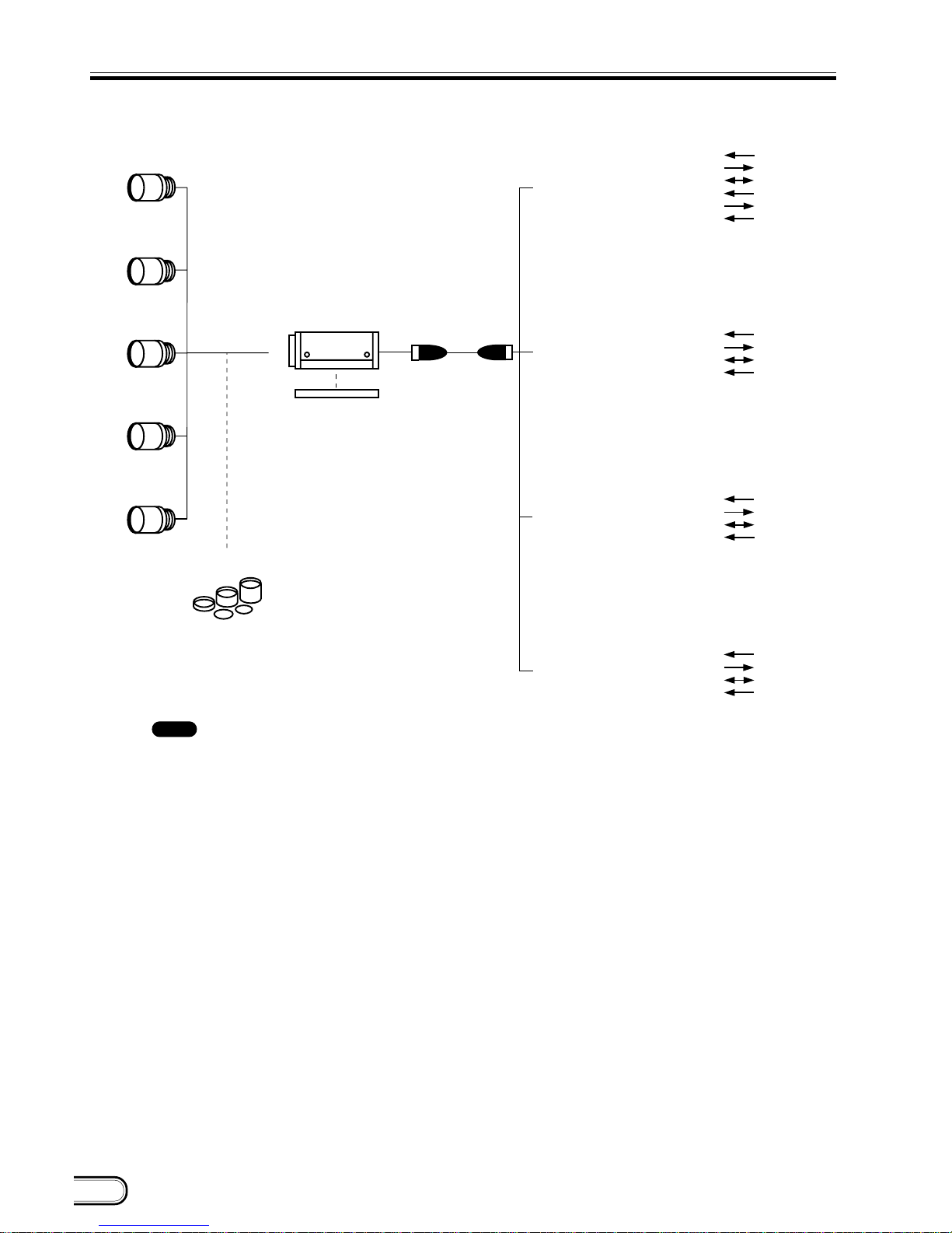
XC-ST70/70CE
LO-77ERK
VCL-16Y-M
(Standard)
VCL-08YM
VCL-12YM
VCL-25Y-M
XC-ST70/70CE
Tripod adaptor
VCT-ST70I
CCXC-12P02N
C-mount lens
Close-up ring kit
VCL-50Y-M
AC
VIDEO OUT
VS
*
2
HD/VD
*
1
AC
VIDEO OUT
VS
*
2
HD/VD
*
1
AC
VIDEO OUT
VS
*
2
HD/VD
*
1
TRIG
WEN
DC +12 V
VIDEO OUT
VS
*
2
HD/VD
*
1
Camera cable
Camera adaptor
DC-77RR/CE
(No trigger input terminal is provided.)
Camera adaptor
DC-777/CE
(No trigger input terminal is provided.)
Camera adaptor
DC-700/CE
(Conforms to new EIAJ and uses 12-pin assignment.)
Junction box
JB-77
(No trigger input terminal is provided.)
CCXC-12P05N
CCXC-12P10N
CCXC-12P25N
*
1: An HD/VD signal cannot be used simultaneously with a VS signal.
*
2: A VS signal cannot be used simultaneously with an HD/VD signal.
: All functions of the XC-ST70/70CE cannot be used when
using DC-777/CE, DC-77RR/CE, and JB-77.
Refer to the table shown below.
5
XC-ST70/70CE
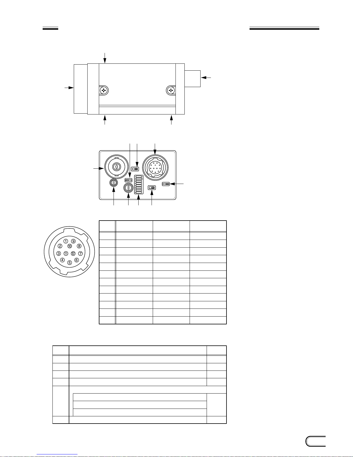
LOCATION OF PARTS AND OPERATION
1 Lens mount section
A commercial C-mount lens as well as a
Sony standard lens can be used.
2 Camera mounting reference hole
These screw holes are positionned with
high precision related to CCD sensor.
3
Screw hole for tripod adaptor mounting
(VCT-ST70I)
4 12-pin multi-connector
DC IN/SYNC (DC power/sync signal input)
5 BNC connector
VIDEO OUT
6 Gamma correction
ON/OFF selector switch
7 Internal/external sync selector
switch
The camera operates with internal synchronization when there is no external
sync input signal in the EXT position.
In this case, an HD/VD signal is not output from the 12-pin multi-connector.
8 Trigger polarity selector switch
This switch can select the polarity (negative or positive) of a trigger pulse.
9 75 Ω termination selector switch
0 Selection DIP switch
Switches 1 to 4:
Selects the shutter speed.
Switch 5: Selects the frame or field
integration.
Switches 6 to 8:
Selects the normal shutter,
external trigger shutter, and
restart/reset.
A GAIN switch
A: Outputs a fixed-level video signal ac-
cording to the brightness of a sub-
ject. (Variable range: 0 to 18 dB)
F: Fixed gain 0 dB
M: Variable gain (Manual)
M (during factory setting):
Adjusted so that all XC-ST70/70CEs
are the same in sensitivity (set by
Sony’s standard value) according to
the deviation in sensitivity of CCD.
Valid when multiple XC-ST70/70CEs
are used for an identical subject.
B Volume control switch
This switch can be changed in the range
of 0 to 18 dB when the GAIN switch is set
to “M”.
During factory setting, this switch is adjusted to the fixed sensitivity for a standard subject.
4 5
2 3
2
1
3
A5B= 9
4
8
67
Pin No.
1
2
3
4
5
6
7
8
9
10
11
12
GND
+12 V
GND
VIDEO output
GND
External HD input
*
1
External VD input
GND
–
*
2
WEN output
TRIG input
GND
External HD/VD
synchronization
Internal HD/VD
synchronization
External VS
synchronization
GND
+12 V
GND
VIDEO output
GND
Internal HD output
Internal VD output
GND
–
*
2
WEN output
TRIG input
GND
GND
+12 V
GND
VIDEO output
GND
–
VS
GND
–
*
2
WEN output
TRIG input
GND
*
1: An input VD signal is required when the restart/reset mode is used.
*
2: A WEN output signal is valid only in the external trigger shutter mode.
Corresponding
No.
6
7
8
9
A
B
Gamma correction ON/OFF selector switch
Internal/external sync selector switch
Trigger polarity selector switch
75-ohm termination selector switch
Selection DIP switch
1, 2, 3, 4: Selects the Shutter speed.
5: Selects the field and frame.
6, 7, 8:
Selects the normal shutter, external trigger shutter, and restart/reset.
GAIN switch
Switch
Factory-setting
mode
OFF
EXT
+
ON
OFF
(All set to
the left.)
FIX
XC-ST70/70CE
4
12-pin multi-connector
• Factory-setting mode of rear panel
CCD
VIDEO CAMERA MODULE
XC-ST70
6
XC-ST70/70CE
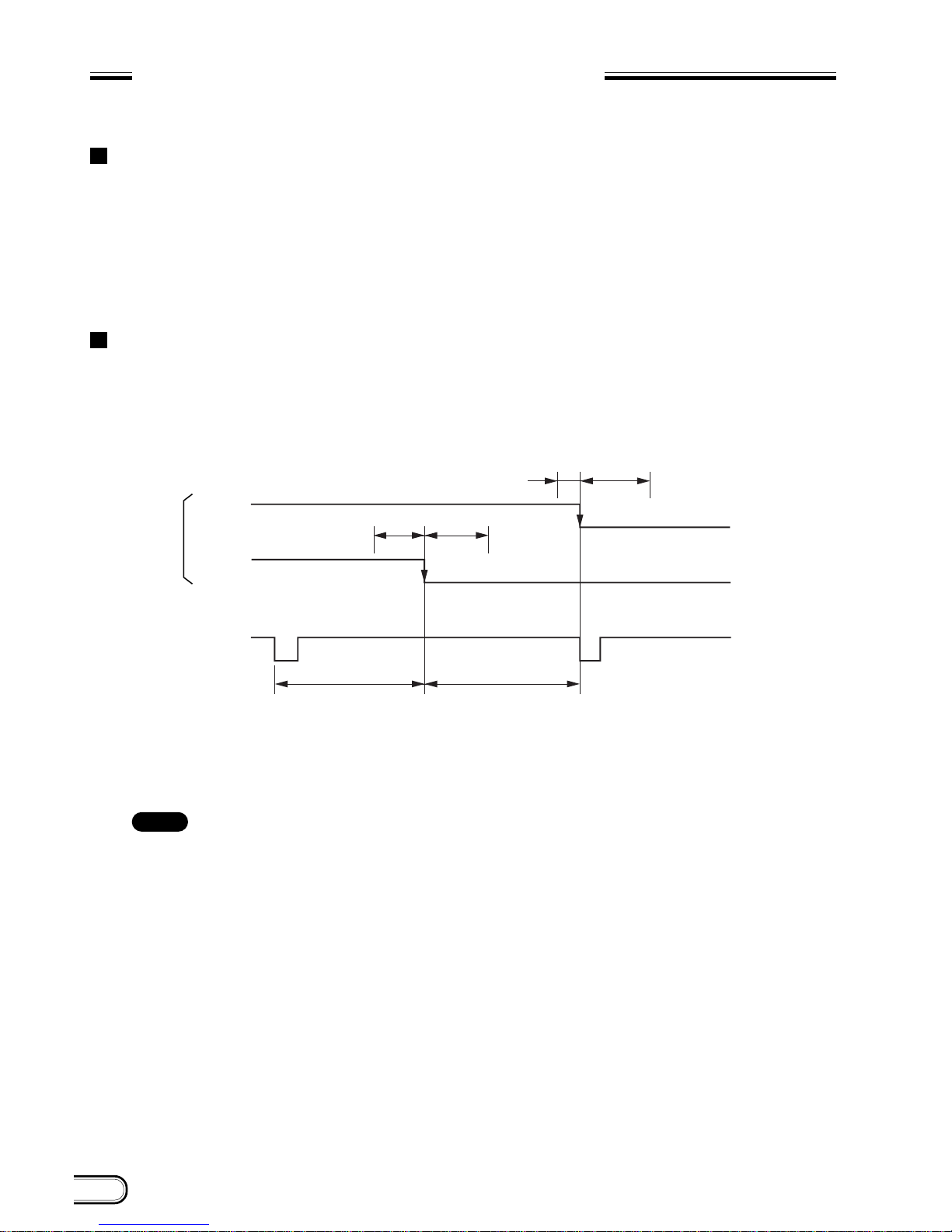
PHASE CONDITIONS OF EXTERNAL
SYNCHRONIZATION
External synchronization for each mode
• For normal video/normal shutter
Continuous HD/VD signal (should conform to EIA and CCIR frequencies in the timing shown in the figure below.)
• For Restart Reset (RR)/external trigger shutter
Continuous HD signal. The phase between VD (reset) and HD signals is as specified in the figure belo w in any
timing.
Phase conditions
The phase relation between external input HD and VD signals should be set as shown below with respect to the
specified center phase.
100 200
455 (454) 455 (454)
5 200
EXT-VD
ODD
(EVEN)
EVEN
(ODD)
EXT-HD
The operation in parentheses refers to XC-ST70CE.
Unit: Clock
1 CLK = 69.84 n sec (XC-ST70)
= 70.48 n sec (XC-ST70CE)
Note
: The synchronized VD signals are delayed for 1H at HD/VD external synchronization mode, while
there is no VD signal delay at VS external synchronization mode.
7
XC-ST70/70CE
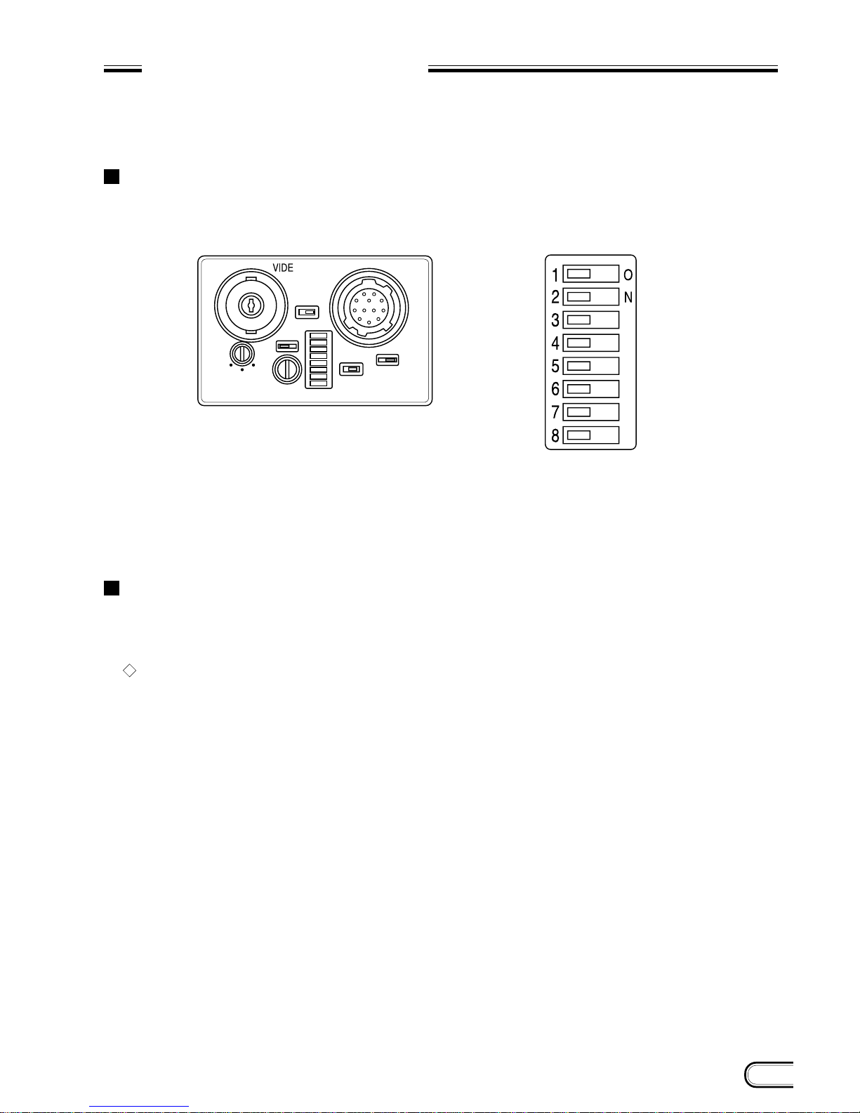
ELECTRONIC SHUTTER
Two types of electronic shutter are provided “normal shutter and external trigger shutter”.
The electronic shutter speed and type can be set using the DIP switch on the rear panel.
DIP switch on the rear panel
Normal shutter
This mode provides continuous video output with the electronic shutter selected by switches to clearly capture a
high-speed moving object.
Setting of normal shutter speed
8
XC-ST70/70CE
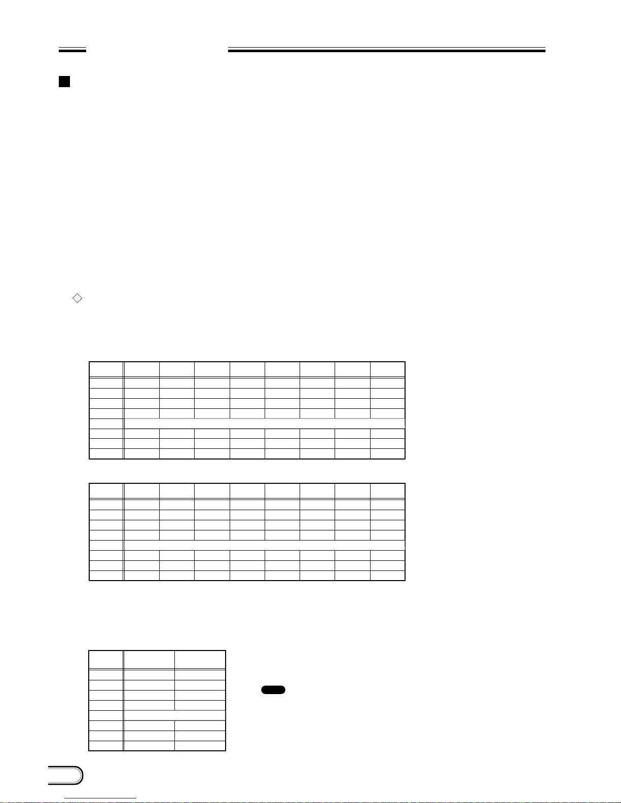
ELECTRONIC SHUTTER
External trigger shutter
These modes are used to capture one image (one field) per trigger pulse.
Set DIP switches 6, 7, and 8 on the rear panel to mode 1 or 2. (Refer to the table below.)
When the trigger pulse width is 1/3 sec or more, the output signal is switched to a normal video signal.
There are two modes for timing in which a video signal is obtained.
• Mode 1 (Non-reset mode)
In this mode, a video signal synchronized with a VD signal is output after a trigger pulse is input.
• A video signal is synchronized with the external VD signal when an external HD/VD signal is input.
• A video signal is synchronized with an internal VD signal when no external HD/VD signal is input.
• Mode 2 (Reset mode)
In this mode, an internal video signal is output from a trigger pulse after a certain period of time.
Video sync is always fixed with odd field for XC-ST70 and even field for XC-ST70CE.
*
For more details of each timing chart, refer to pages 16 to 23.
Setting of external trigger shutter speed
There are two ways to set the shutter speed.
• Using DIP switch on the rear panel
• Using trigger pulse width
• An arbitrary shutter speed can be obtained by setting the trigger pulse width to the range of 2 µsec to 250
msec.
Exposure time = Trigger pulse width + 97 µsec (XC-ST70)
120 µsec (XC-ST70CE)
–
–
–
1
0
1
1
1
0
0
0
0
1
1
0
1
0
0
0
1
1
1
1
0
0
0
1
1
0
0
1
0
0
1
1
1
0
1
0
0
1
1
0
1
1
0
0
1
1
1
1
1
0
0
1
1
Mode 1 (Non-reset mode)
–
–
–
1
0
0
1
1
0
0
0
0
0
1
0
1
0
0
0
0
1
1
1
0
0
0
0
1
0
0
1
0
0
0
1
1
0
1
0
0
0
1
0
1
1
0
0
0
1
1
1
1
0
6
0
0
1
Switch
1
2
3
4
5
6
7
8
*
1/100
*
1/100
1/125 1/250 1/500 1/1000 1/2000 1/4000
**
1/10000
Frame: 0 / Field: 1
Mode 2 (Reset mode)
Switch
1
2
3
4
5
6
7
8
1/125 1/250 1/500 1/1000 1/2000 1/4000
**
1/10000
Frame: 0 / Field: 1
*
The external trigger shutter speed is set to
1/100 sec for XC-ST70(EIA) and 1/120
sec for XC-ST70CE(CCIR).
**
The external trigger shutter speed is
set to 1/10000 sec for XC-ST70(EIA) and
1/8000 sec for XC-ST70CE(CCIR).
1: ON
0: OFF
–: Any
0
0
0
0
0
1
1
0
0
0
0
0
0
1
Switch
Mode 1
(Non-reset mode)
Mode 2
(Reset mode)
1
2
3
4
5
6
7
8
Frame: 0 / Field: 1
: 1. lt is recommended to set DIP switch 5 for field selection.
(The field selection is about two times in sensitivity as high as the frame selection.)
2. After a trigger pulse is input, a new trigger pulse must not be input before the video
signal obtained by the trigger pulse has been output.
1: ON
0: OFF
Note
 Loading...