

Sony XBR-65HX955 Schematic
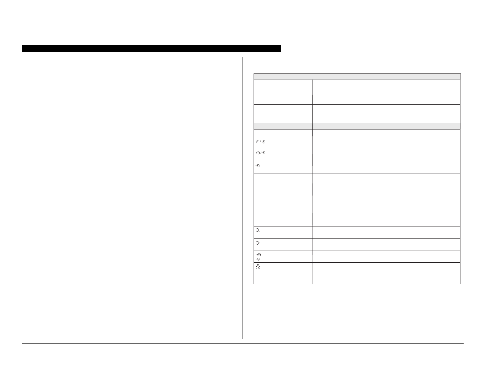
Self Diagnosis
Supported model
HISTORY INFORMATION FOR THE FOLLOWING MANUAL:
SERVICE / TRAINING MANUAL
AZ3G Chassis
ORIGINAL MANUAL ISSUE DATE: 10/2012
Version Date Subject
1.0 10/15/2012 Original Manual Release Date.
Segment: 2b-1N
LCD Digital Color TV
9-888-514-01

Self Diagnosis
Supported model
SERVICE / TRAINING MANUAL
AZ3G Chassis
Segment: 2b-1N
XBR-65HX955
LCD Digital Color TV
9-888-514-01

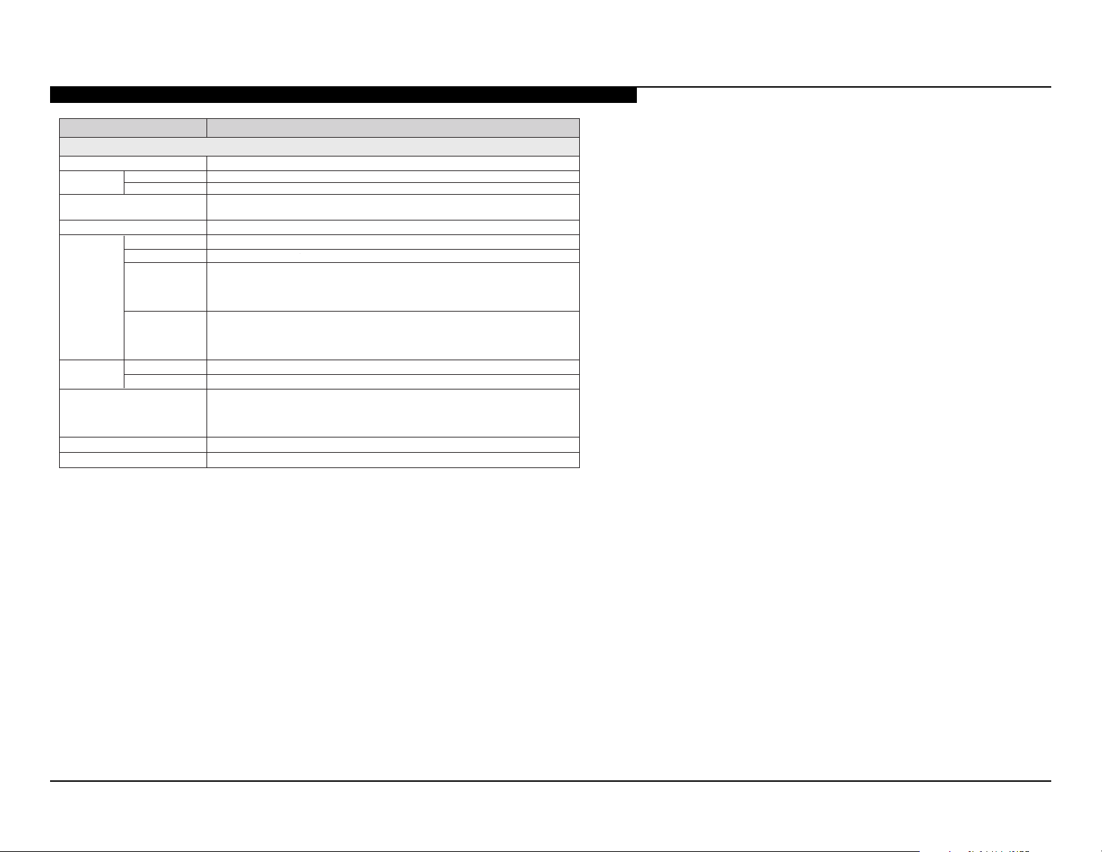
MODEL LIST
MODEL COMMANDER DESTINATION MODEL COMMANDER DESTINATION
XBR-65HX955 RM-YD078 BRAZIL
9-888-514-01
TABLE OF CONTENTS
Cautions and Warnings ..................................................................................iii
Section 1 - Features and Overview ................................................................1
Features ........................................................................................................1
Specications ................................................................................................1
Checking the Accessories .........................................................................2
Chassis Overview .......................................................................................... 3
Overall Circuit Description ............................................................................. 4
Main Board ...............................................................................................4
Power Supply Board ................................................................................. 4
IR Board .................................................................................................... 4
3D IR Emitter Board .................................................................................. 5
Wireless LAN Card ...................................................................................5
Switch Unit ................................................................................................ 5
LCD Panel Assembly ................................................................................5
Section 2 - Troubleshooting ...........................................................................6
Overview .......................................................................................................6
Updating the Software ..............................................................................6
Self Diagnosis Function ................................................................................. 6
Standby LED Blink Count .........................................................................6
Viewing the Self Check Diagnosis History ................................................ 7
Triage Chart ...................................................................................................9
Section 4 - Disassembly/Part Number Information ....................................17
Loop Stand Removal ................................................................................... 17
Rear Cover Removal ................................................................................... 19
Rear Cover Caution ................................................................................ 19
Reattaching the Rear Cover ...................................................................20
Handling the LVDS FFC Connector .............................................................21
Disconnecting the LVDS FFC Connector ...............................................21
Connecting the LVDS FFC Connector .................................................... 21
Chassis Assembly Removal ........................................................................22
LCD Panel Assembly Removal ...................................................................23
LCD Panel Assembly Handling Instructions ...........................................23
LCD Frame Removal .............................................................................. 24
Cleaning the LCD Panel .........................................................................24
Connectors ..................................................................................................25
Screws ......................................................................................................... 26
Accessories and Packaging ........................................................................27
Miscellaneous .............................................................................................. 27
Optional Accessories ...................................................................................27
Remote Commander ...................................................................................27
Wire Dressing .............................................................................................. 28
Section 3 - Flow Charts and Diagrams ........................................................10
Block Diagram .............................................................................................10
No Power ..................................................................................................... 11
Standby LED Blinking .................................................................................. 13
No Picture .................................................................................................... 14
No 3D Viewing .............................................................................................16
XBR-65HX955 i
Section 5 - Updates and Adjustments .........................................................29
Overview .....................................................................................................29
Software Updates for Customers ................................................................29
Software Updates for Servicers ................................................................... 30
Software Update Responsibility .............................................................. 30
Checking the Software Version ...............................................................30
Completing Service Requirements When Replacing the Main Board ......... 30
Updating the Software ............................................................................31
Selecting the Destination ........................................................................ 32
Selecting the Model Name ...................................................................... 33
Adding the Serial Number ....................................................................... 33
Conrming the Model ID and Product ID ................................................ 35
Clearing the Self Check Diagnosis History ............................................. 36
Resolving an 8 Blink Error ........................................................................... 37
Verifying There is an 8 Blink Error ..........................................................38
Resetting the TV to Factory Condition ....................................................38
Updating the Software ............................................................................38
Replacing the Main Board ......................................................................39
Completing Service Requirements When Replacing the LCD Panel ......... 39
Updating the Software ............................................................................39
Conrming the Model ID and Product ID ................................................ 40
Resetting the Panel Operation Time .......................................................41
Clearing the Self Check Diagnosis History ............................................. 42
Optional Adjustments ..................................................................................42
Enabling VCOM to Adjust the Picture .....................................................42
Setting White Balance Adjustments ........................................................43
Resetting the TV to Factory Condition ....................................................44
Resetting the TV to Factory Condition Using Service Mode ................... 44
TABLE OF CONTENTS
Appendix A: Encryption Key Components ...............................................A-1
XBR-65HX955 ii

CAUTIONS AND WARNINGS
CAUTION!!
These servicing instructions are for use by qualied service personnel only.
To reduce the risk of electric shock, do not perform any servicing other than
that contained in the operating instructions unless you are qualied to do so.
WARNING!!
An isolation transformer should be used during any service to avoid possible
shock hazard, in case of live chassis.
!
SAFETY-RELATED COMPONENT WARNING!!
There are critical components used in LCD color TVs that are important for
safety. These components are identied with shading and
schematic diagrams and the parts list. It is essential that these critical parts
be replaced only with the part number specied in the parts list to prevent
electric shock, re or other hazard.
!
mark on the
NOTE: Do not modify the original design without obtaining written permission
from the manufacturer or you will void the original parts and labor warranty.
ATTENTION!!
For safety reasons, component level repair of the Power Supply Boards
and/or the Inverter Boards is prohibited.
XBR-65HX955 iii
CAUTIONS AND WARNINGS
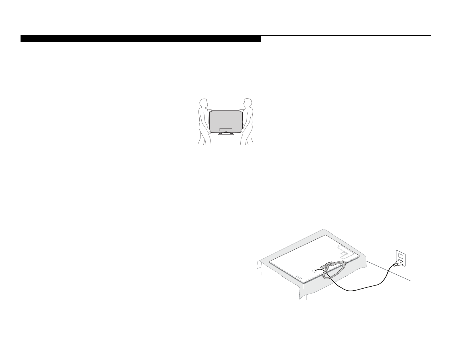
SETTING UP AND CARRYING THE TV
● Disconnect all cables when carrying the TV.
● Carry the TV with the adequate number of people; larger size TVs require two or more people.
● Correct hand placement while carrying the TV is very important for safety and to avoid damage.
USE CAUTION WHEN HANDLING THE LCD PANEL
When repairing the LCD Panel, be sure you are grounded by using a wrist band.
When installing the LCD Panel on a wall, the LCD Panel must be secured using the 4 mounting holes on the Rear Cover.
1. Do not press on the panel or frame edge to avoid the risk of electric shock.
2. Do not scratch or press on the panel with any sharp objects.
3. Do not leave the module in high temperatures or in areas of high humidity for an extended period of time.
4. Do not expose the LCD Panel to direct sunlight.
5. Avoid contact with water. It may cause a short circuit within the module.
6. Disconnect the AC power when replacing the backlight or Inverter circuit.
(High voltage occurs at the Inverter circuit at 650Vrms).
7. Always clean the LCD Panel with a soft cloth material.
8. Use care when handling the wires or connectors of the Inverter
circuit. Damaging the wires may cause a short.
9. Protect the panel from ESD to avoid damaging the electronic
circuit (C-MOS).
10. During the repair, DO NOT leave the Power On for more than
1 hour while the TV is face down on a cloth.
XBR-65HX955 iv

CAUTIONS AND WARNINGS
CLEANING THE LCD PANEL
CAUTION: When cleaning the TV, be sure to unplug the power cord to avoid any chance of electric shock.
Clean the cabinet of the TV with a dry soft cloth.
Wipe the LCD screen gently with a soft cloth.
; Stubborn stains may be removed with a cloth slightly moistened with a solution of mild soap and warm water.
; If using a chemically pretreated cloth, please follow the instruction provided on the package.
; Never use strong solvents such as a thinner, alcohol or benzine for cleaning.
; Periodic vacuuming of the ventilation openings is recommended to ensure proper ventilation.
; Do Not use paper towels, any type of abrasive pad, rags, rubber or vinyl materials to clean the screen. Using these materials could easily scratch the
screen which may result in permanent damage.
; Do Not use any cleaning product containing alkaline/acid cleaner, scouring powder or volatile solvent, such as alcohol, ammonia, benzine, thinner or
insecticide. Using any of these harsh cleaners may result in permanent damage to the screen.
; Do Not spray water or detergent directly onto the TV screen. If liquid drips into the bottom of the screen it may cause a failure.
XBR-65HX955 v

CAUTIONS AND WARNINGS
To Exposed Metal
Parts on Set
0.15 µF
Earth Ground
AC
Voltmete
r
(0.75V)
Trouble Light
SAFETY CHECK-OUT
After correcting the original service problem, perform the following safety
checks before releasing the set to the customer:
1. Check the area of your repair for unsoldered or poorly soldered
connections. Check the entire board surface for solder splashes
and bridges.
2. Check the interboard wiring to ensure that no wires are “pinched”
or touching high-wattage resistors.
3. Check that all control knobs, shields, covers, ground straps and
mounting hardware have been replaced. Be absolutely certain
that you have replaced all the insulators.
4. Look for unauthorized replacement parts, particularly transistors,
that were installed during a previous repair. Point them out to the
customer and recommend their replacement.
5. Look for parts which, though functioning, show obvious signs of
deterioration. Point them out to the customer and recommend
their replacement.
6. Check the line cords for cracks and abrasion. Recommend the
replacement of any such line cord to the customer.
7. Check the antenna terminals, metal trim, “metallized” knobs,
screws and all other exposed metal parts for AC leakage. Check
leakage as described in “Leakage Test”.
LEAKAGE TEST
3. Measuring the voltage drop across a resistor by means of a VOM
or battery-operated AC voltmeter. The “limit” indication is 0.75 V, so
analog meters must have an accurate low voltage scale. Nearly all
battery-operated digital multimeters that have a 2 VAC range are
suitable. (see Figure A)
Figure A. Use an AC voltmeter to check AC leakage.
HOW TO FIND A GOOD EARTH GROUND
The cover-plate retaining screw on most AC outlet boxes is at earth ground.
Verify the AC outlet box retaining screw ground by connecting a 60W to
100W incandescent (not a neon or uorescent lamp) between the hot side of
the receptacle and the retaining screw. Try both slots, if necessary, to locate
the hot side on the line; the lamp should light at normal brilliance if the screw
is at ground potential. (see Figure B)
XBR-65HX955 vi
The AC leakage from any exposed metal part to earth ground and from all
exposed metal parts to any exposed metal part having a return to chassis,
must not exceed 0.5 mA (500 microamperes). Leakage current can be
measured by any one of three methods.
1. A commercial leakage tester.
Follow the manufacturers’ instructions provided with the tester.
2. A battery-operated AC milliammeter.
AC Outlet Box
Figure B. Checking for earth ground.
SECTION 1 - FEATURES AND OVERVIEW
Sistema
Sistema de televisão Analógico: NTSC/PAL-M/PAL-N
Digital: SBTVD
Cobertura de canais
CATV (analógico): 1-135
Sistema do painel
Potência de saída dos alto-falantes
(RMS)
Tomadas de entrada/saída
CABLE/ANTENNA
Terminal de antena externa de 75 ohms para entradas RF
VIDEO IN 1Entrada de vídeo / áudio (tomadas RCA)
COMPONENT IN
VIDEO IN 2
YP
BPR
(vídeo componente): 1080p (50, 60 Hz), 1080i (50, 60 Hz), 720p (50, 60 Hz), 576p,
576i, 480p, 480i
Entrada de áudio (tomadas RCA)
Entrada de vídeo (plugue RCA comum com entrada Y)
HDMI IN 1/2/3/4
Vídeo (2D): 1080p (30, 50, 60 Hz), 1080/24p, 1080i (50, 60 Hz), 720p (30, 50, 60 Hz), 576p,
576i, 480p, 480i, Formatos PC
Vídeo (3D):
Frame Packing: 1080p (30 Hz), 1080/24p, 1080i (50, 60 Hz), 720p (30, 50, 60 Hz), 720/24p
Lado a lado (Side-by-Side): 1080p (50, 60 Hz), 1080/24p, 1080i (50, 60 Hz), 720p(30, 50, 60 Hz)
Cima baixo (Over-Under) 1080p (30, 50, 60 Hz), 1080/24p, 1080i (50, 60 Hz), 720p (50, 60 Hz)
Áudio: Dois canais PCM lineares: 32; 44,1 e 48 kHz, 16, 20 e 24 bits, Dolby Digital
Entrada de áudio analógico (minitomada estéreo) (somente HDMI IN 2, comum com PC IN)
ARC (Audio Return Channel - Canal de Retorno de Áudio) (somente HDMI IN 1)
AUDIO OUT
(Salida de audio)/Auriculares
Minitomada estéreo
DIGITAL AUDIO OUT
PC IN
PC/HDMI 2 AUDIO IN
RGB analógico (Mini D-sub de 15 pinos)
Entrada de áudio (minitomada estéreo) (comum com HDMI IN 2)
Conector 10BASE-T/100BASE-TX (A velocidade de conexão pode ser diferente dependendo
NAL
do ambiente de rede. A taxa e a qualidade de comunição de 10BASE-T/100BASE-TX não
estão garantidas nesta TV)
Consulte o i-Manual para obter informações sobre o formato suportado.USB/DLNA
VHF: 2-13, UHF: 14-69
Painel LCD (tela de cristal líquido)
10 W + 10 W (8 ohms, 1 kHz, 10% TDH*,127V) + 10 W (8ohm, 100 Hz, 10% TDH*,127V)
Tomada digital óptica (PCM linear de dois canais, Dolby Digital)
(OPTICAL)
FEATURES
The AZ3G chassis is one of several designs for the 2012 model line of Sony
Bravia® LCD televisions. This manual covers the following models:
XBR-65HX955
The BRAVIA® HX95x series features a truly transcendent picture quality,
each scene in everything you watch - HD movies, 3D, sports, even
YouTube™ clips - is presented with unprecedented detail and astonishing
color from Sony’s exclusive X-Reality™ PRO picture engine. Ultra-clear,
realistic motion during slow scenic sweeps and fast action sports comes
courtesy of Motionow™ XR 960.
● Pro-grade detail for discerning eyes: X-Reality™ PRO
● Experience precise motion clarity with Motionow™ XR 960
1. Broadband speed of at least 2.5 Mbps recommended (10 Mbps for HD). Content subject to
2. Requires 3D content, 3D player, HDMI® cable (at least 10.2 Gbps) and 3D active glasses
3. Streaming content, copy-protected content and certain formats are not supported.
4. Requires devices connected to the same wireless home network.
● Frameless design with Corning’s Gorilla
● Movies, music & apps with Sony Entertainment Network
● Amazingly crisp, natural 3D effects in every 3D scene
● Dynamic Edge LED backlight for amazing contrast & color
● Stream HD entertainment wirelessly with built-in Wi-Fi
● PC and tablet content3 on your TV with Intelligent Connect
● Make life-sized video calls with Skype
● Media Remote™ app to control your TV with a smartphone
● Connect to the TV via Wi-Fi
change and may require fees. Skype requires CMU-BR100 camera sold separately. Subject
to Skype’s terms and conditions.
sold separately.
1
®
Glass
1
®
1
®
without using a router
SPECIFICATIONS
1
2
1
®
4
3
* Distorção harmônica total.
XBR-65HX955 1
SECTION 1 - FEATURES AND OVERVIEW
- Controle remoto (1)*
- Pilhas tipo AAA (2)
- Parafusos de xação do pedestal
- Parafusos de montagem do pedestal
- Manual de instruções (este manual) e outros
documentos
* Consulte o nome do modelo impresso no controle remoto.
* Os valores de tamanhos de tela, dimensôes e pesos são aproximados.
• A disponibilidade dos accesórios opcionais depende do país/região/modelo de TV/estoque.
Alimentação e outros
Requisitos de alimentção
Consumo de
energia
em uso
Menos de 0,35 Wem standby
Tamanho da tela*
(medido diagonalmente)
163,9
64,5
Resolução do monitor
Dimensoes*
com pedestal
sem pedestal
padrão de
furo para
montagem na
parede
(mm)
400 x 300
tamanho do
parafuso para
montagem na
parede
(mm)
M6 (8-12 mm)
com pedestal
sem pedestal
Temperatura de operação
65HX955
110-220 V CA, 60 Hz
Nome do modelo XBR
251 W
(polegadas)
(cm)
1920 pontos (horizontal) × 1080 linhas (vertical)
1506 x 965 x 374
(mm)
1506 x 901 x 51
(mm)
47,7
(kg)
43,6
(kg)
Peso*
0 ºC – 40 ºC
Accesorios opcionais Suporte da TV: SU-B463S
Óculos 3D: TDG-BR750/TDG-BR250/TDG-BR200/TDG-BR100/TDG-BR50
Unidade de cámera e microfone: CMU-BR100
Adaptador USB Wireless LAN: UWA-BR100
Umidade de operação
10 % - 80 % RH (sem condesação)
• Projeto e especicações técnicas sujeitos a alterações sem prévio aviso.
CHECKING THE ACCESSORIES
XBR-65HX955 2

SECTION 1 - FEATURES AND OVERVIEW
CHASSIS OVERVIEW
The primary circuits in the AZ3G chassis consist of a Main Board (BAPS Board), Power Supply Board (G14/G15 Boards), the IR Board (HL Board), the 3D IR
Emitter (HEM3 Board), the Wireless LAN Card, the Switch Unit, and the LCD Panel Assembly which includes the TCON Board and LD Board.
NOTE: For Connector part number information, refer to “Connectors” on page 24. For Wire Dressing information, refer to “Wire Dressing” on page 26.
SWITCH
UNIT
HEM3
G15
LD
G14
TCON
BOARD LAYOUT FOR XBR-65HX955
WIRELESS
LAN CARD
BAPS
HL
XBR-65HX955 3
SECTION 1 - FEATURES AND OVERVIEW
OVERALL CIRCUIT DESCRIPTION
The “Block Diagram” on page 10 provides an overview of the AZ3G
chassis. The following are descriptions of the boards and their functions.
MAIN BOARD
Common to all models the Main Board, designated as the BAPS Board,
contains the TV control, video and audio processing circuitry. All these
functions are accomplished using the X-Reality Processor IC9000.
TUNER
The tuner is a combination analog/digital unit. It can receive traditional
analog NTSC signals via cable or terrestrial along with digital SBTVD.
X-REALITY PROCESSOR
IC9000 performs the majority of the necessary audio and video processing
on the Main Board.
TV Microprocessor: The CPU internal to the X-Reality processor controls
all aspects of the television functions. Input from the user along with
monitoring of critical circuits is also performed by this CPU.
Digital Audio and Video Decoder: The MPEG2 and Digital Dolby audio
streams are received from the tuner for decompression. All video sources
which are not native 1920 X 1080p 60HZ are scaled to this resolution.
Digital audio content is output to the class D amplier for processing and
amplication.
HDMI Input and Switching: The customer can select from the HDMI1
through HDMI4 input via the HDMI switch IC5500. Each HDMI input contains
a common EDI NVM (internal to IC5500) to provide display information data
to any device connected via the HDMI inputs.
LVDS Transmitter: Integrated into IC9000 is a Low Voltage Differential
Signaling (LVDS) transmitter. This circuit converts the 8-bit parallel RGB
video information into a set of high speed serial lines for noise-free
transmission to the TCON Board circuits located internally to the LCD Panel.
Scan Converter: Signal processing circuit that performs resolution
conversion (aspect ratio) and interlaced to progressive scan (IP) conversion.
AUDIO AMPLIFIER
The main speaker audio amplier (IC4601) and sub-woofer amplier
(IC4701) amplies the digital audio output of the X-Reality Processor and
sends it to the speakers.
TEMPERATURE SENSOR
The temperature sensor detects over-temperature conditions on the Main
Board, LCD Panel or ambient room temperature and sends the shutdown
signal to the processor.
POWER SUPPLY BOARD
The Power Supply Boards used in this model are:
● G14 and G15 Boards
There are 3 distinct sections on the power supply:
Standby Supply: Continuously operational as long as AC power is applied,
the standby supply generates 3.3V for the circuits requiring power while the
unit is turned off. An unregulated 19V line is present to provide power to the
main relay, PFC and main power supply at turn-on.
Main Supply: Once the power supply receives a power-on command from
the CPU on the Main Board, the main switching supply is turned on to
provide a regulated 12V source and Audio 12V.
Converter: Generates the B+ and B- voltages for the LED backlights.
IR BOARD
Designated as the HL Board, the IR Board contains the power, standby
and timer LED’s that are located on this board along with the IR Remote
Receiver and light level sensor.
3D IR EMITTER BOARD
Designated as the HEM3 Board, this board is the internal 3D IR Emitter to
synchronize the 3D shutter glasses.
XBR-65HX955 4

SECTION 1 - FEATURES AND OVERVIEW
WIRELESS LAN CARD
The wireless transmit/receive circuits are located on this board to
communicate with a wireless network.
SWITCH UNIT
This board contains the power, channel and volume up/down, and menu
buttons.
LCD PANEL ASSEMBLY
The LCD Panel Assembly includes the LCD Panel, TCON Board and LED
Backlight system.
NOTE: The LD Board is not always included with the LCD Panel. Check
with the LCD Panel manual for the most update information regarding this
information.
The LCD Panel contains the actual liquid crystals, color lters and
polarizers. The liquid crystals are manipulated by the applied voltage to
pass a specic amount of light - from the backlight- depending on the level
of voltage applied.
The TCON performs all the control, timing, charge and discharge functions
driving the operation of the LCD Panel.
A new LCD Panel Assembly will include the following items:
● LCD Panel
● LED Backlighting System (varies)
● TCON Board
● LD Board
TCON BOARD
The TCON Board communicates between the LCD Panel and the
microprocessor on the Main Board.
NOTE: The TCON Board is not available as a replacement part for all
models. To determine if the TCON Board is available as a replacement
part, refer to the LCD Panels Manual.
XBR-65HX955 5

SECTION 2 - TROUBLESHOOTING
Self Diagnosis
Supported model
OVERVIEW
This chapter provides information regarding the Self Diagnosis feature in
our TVs.
UPDATING THE SOFTWARE
The Self Diagnosis function is designed to provide information
regarding the problem with the TV, however, there are several issues
that may be resolved by updating the TV software to the latest version.
Most symptoms that are correctable by software updates involve
communications issues with other devices or minor glitches in the operation
of a specic function. Below is a list of some of the symptoms that may be
corrected with a software update:
● Fluctuations in picture brightness
● Intermittent picture freezing or noise
● Problems with certain inputs (especially HDMI)
● Intermittent or distorted audio
● Erratic remote control operation
● TV turns on and off by itself
● Loss of color
● Internet connectivity (internet models only)
● Certain features not working correctly
(photo or video le viewing)
SELF DIAGNOSIS FUNCTION
Critical voltages and circuit operations are monitored by the CPU on the
Main Board. If an error is detected the Self Diagnosis function in the TV will
force the TV to shut down by the CPU. The monitored circuit in which the
fault occurred will automatically cause the CPU to blink the Standby LED
in groups of repeating sequences. The number of times the Standby LED
blinks indicates the possible cause of the problem.
Not all of the available protect codes are used in every model. For example,
models that don’t have the local dimming feature do not use the 4X blink
error as this circuit is found in models that are backlit with uorescent lamps.
The information in this section provides guidance in locating the possible
component causing the shutdown.
STANDBY LED BLINK COUNT
2 times
5 times
Standby LED
LED ON 0.3 sec.
LED OFF 0.3 sec.
LED DISPLAY & BLINK COUNT
LED OFF
3 sec.
XBR-65HX955 6

SECTION 2 - TROUBLESHOOTING
StandBy LED
*Format of Error History = YYMMDDhhmmss example 120123132522= Jan 23, 2012 13:25:22 (1:25:22PM)
VIEWING THE SELF CHECK DIAGNOSIS HISTORY
When an error is detected, the Self Check screen records the date(s) and
the number of times the error occurred. This is helpful in conrming past
occurrences of an error and for determining if an error is intermittent when
the customer is not sure what is causing the television to shut down. If the
screen displays a “0”, no error has occurred.
1. Take the TV out of deep Standby mode by pressing
turn on the TV.
POWER
to turn the TV back off.
Channel 5 Volume -
POWER
2. Press
3. Press the following buttons on the Remote Commander within a
second of each other:
DISPLAY
NOTE: This differs from accessing Service Adjustments Model
(Volume +).
POWER
to
Blink Count
Diagnosis
Item
SELF CHECK
000 RESERVED --------------------- ------------------------------------------ 00
000 RESERVED --------------------- ------------------------------------------ 00
002 MAIN_POWE --------------------- ------------------------------------------ 00
003 DC_ALERT --------------------- ------------------------------------------ 00
003 AUD_PROT --------------------- ------------------------------------------00
003 HDMI_EQ --------------------- --------------------- --------------------- 00
003 TU_DEMOD --------------------- --------------------- --------------------- 00
004 VLED --------------------- ------------------------------------------00
004 LD_ERR --------------------- ------------------------------------------00
005 HFR_ERR --------------------- ------------------------------------------ 00
005 TCON_ERR 120123132522 120123113645--------------------- 02
005 P_ID-ERR --------------------- --------------------- --------------------- 00
006 BACKLITE --------------------- ------------------------------------------00
007 TEMP_ERR --------------------- --------------------- --------------------- 00
007 FAN_ERR --------------------- ------------------------------------------00
010 EMITTER --------------------- --------------------- --------------------- 00
101 VPC_WDT --------------------- --------------------- --------------------- 00
102 MEPS_WDT --------------------- ------------------------------------------ 00
103 HOST_WDT --------------------- ------------------------------------------ 00
104 STBY_WDT --------------------- ------------------------------------------00
00345 000333 06789
Panel operation time by hour (MAX:65535)
Panel operation time by hour (MAX:65535)
Boot count (MAX:65535)
Boot count (MAX:65535)
Total operation time by hour (MAX:65535)
Total operation time by hour (MAX:65535)
Date and Time Display*
Error Count
(00-99)
XBR-65HX955 7
NOTE: date and time must be set for this to work
SAMPLE SELF CHECK DIAGNOSIS PAGE
 Loading...