

Sony XBR-55X800E Schematic

HISTORY INFORMATION FOR THE FOLLOW ING MANUAL:
SERVICE MANUAL (UNIQUE)
Segment: KF - America
Version Date Subject
1 03/2017 1
st
Issue.
GN3TR CHASSIS
LCD TV
9-888-720-A1
For SM - Common , pleas e ref er :
9-888-720-0X

SERVICE MANUAL (UNIQUE)
Segment: KF - America
GN3TR CHASSIS
LCD TV
MODEL LIST
MODEL REMOTE DESTINATION
XBR-43X800E
XBR-49X800E RMF-TX300U UC2
XBR-49X800E/S RMF-TX300U LA1
XBR-49X805E/S RMF-TX300B LA8
XBR-49X807E/S RMF-TX300B
XBR-55X800E RMF-TX300U UC2
XBR55X800E/S RMF-TX300U LA1
XBR55X805E/S RMF-TX300B AR4 , LA8
XBR55X807E/S RMF-TX300B CO1
XBR-55X806E RMF-TX300U LA1
RMF-TX300U UC2
CO1
3
TABLE OF CONTENTS
Section Title Page
1. DISSASSEMBLY AND REMOVAL CAUTION……………………… 5
2. DIAGRAMS
2-1.
2-2.
3. DISASSEMBLY, EXPLODED VIEWS AND OTHER PARTS
3-1. XBR-43X8*E ……………….……………………………. 49
3-2 XBR-49X8*E ……………….……………………………. 55
3-3 XBR-55X8*E ……………….……………………………. 61
Circuit Board Location…..……………………………………. 15
Wire Dressing…………………………………………………. 16
Please refer Serv ice Manual – Common for below information :
General Safety Notes
Self Diagnostic Function
Triage Chart
Troubleshooting, T roubleshooting reference
Adjustments
Diagrams : Block Diagram , Connector Diagram
Note: Pictures prov ided in all this sect ion might ha ve s light diffe re nce f rom the
actual sets
4
SECTION 1
DISSASSEMBL Y AND REMOVA L CA UTION
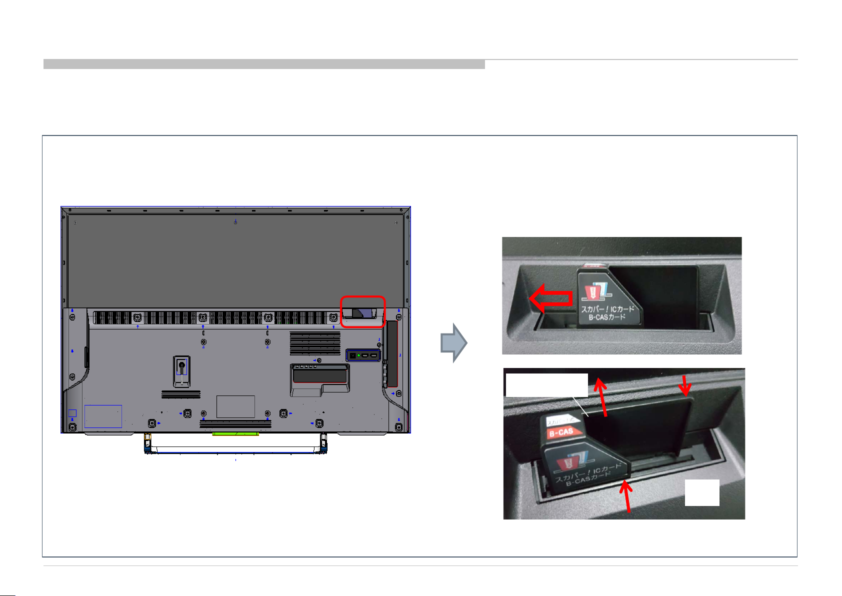
1-1. Rear Cover Dis assembl y M ethod and Caution Notes
1-1-1 (a). Bracket Top Flap (FRE) di sm antle gui de (before rem ovi ng rear cover (RC ) ) ( For Japan Model only )
① Slide Bracket Top Flap to the left side until end
② Push side of Bracket Top Flap to release hooking
③ Pull up Bracket Top Flap.
①
TOP FLAP
③
②
2mm
RC
②
5
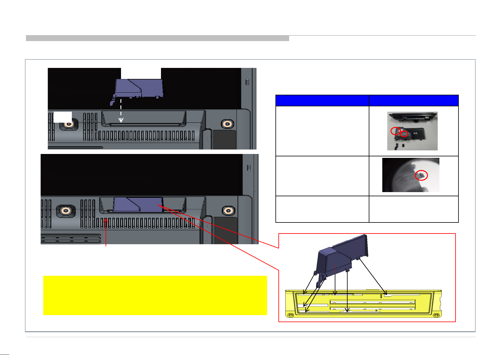
1-1-1 (b) Bracket Top Flap (FRE) assembly guide (after assemble r ear cover (RC ))
RC
TOP FLAP
※ Note: Bracket Top Flap need to full fill below criteria.
In case of NG please replace with new parts.
OK基準 NG事例
① No broken hook at
both side
②There is not more than
1/2 of the deformation
and damage at hook
③TOP Flap does not come
off after assembly.
TOP FLAP
When vi ewed from the rear side of inserti ng the ri bs of TOP FLAP to
the bracket on the left side alignment .
※After r epairi ng proces s compl eted, pleas e inser t card iand slide the
Bracket Top Flap to the right to actuates the
Switch on the TV set. Car d cannot be functioni ng if the swi tch s not
actuates and broadcasting cannot be viewed.
6
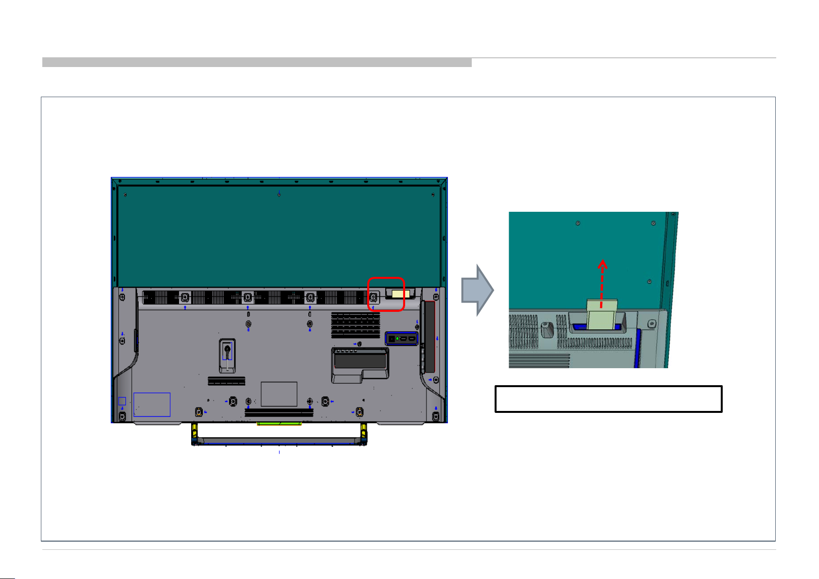
1-1-2. DUMMY CARD PCMCI A dismantle guide (before removing rear cover (RC))
Pull up Dummy card PMCIA
7
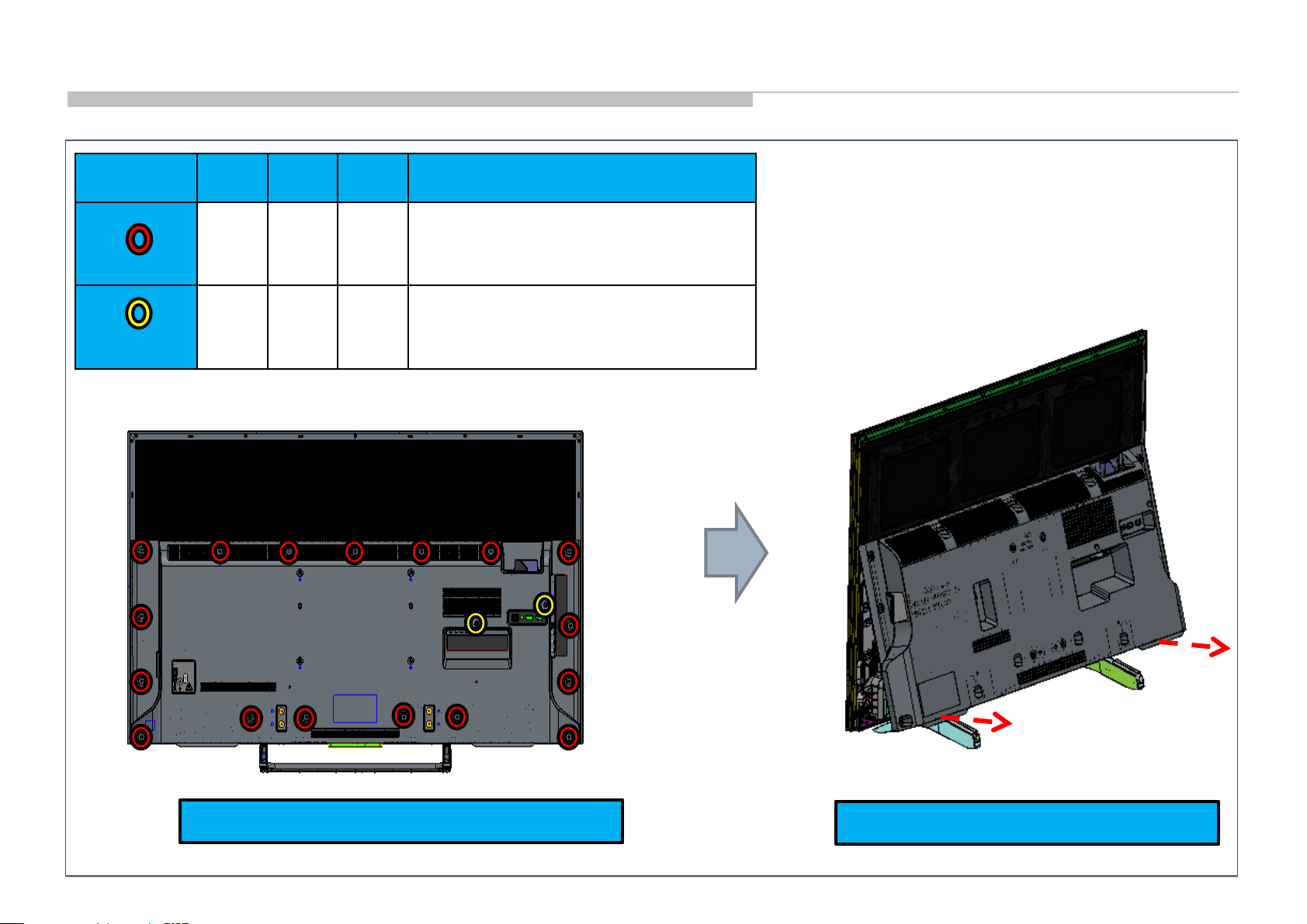
1-1-3. Screw type and quantity to di ssem ble RC
Reference 43” 49” 55” Remarks
c
13
2 2 2
14
17
4-167-019-22
SCREW, +PSW M3X8
7-685-647-79
SCREW +BVTP 3X10 TYPE2 IT-3
Step1)Ensure all screws is removed.
*Rear cover can be dissembled without detach stand
Step 2)Take out the rear cover.
8
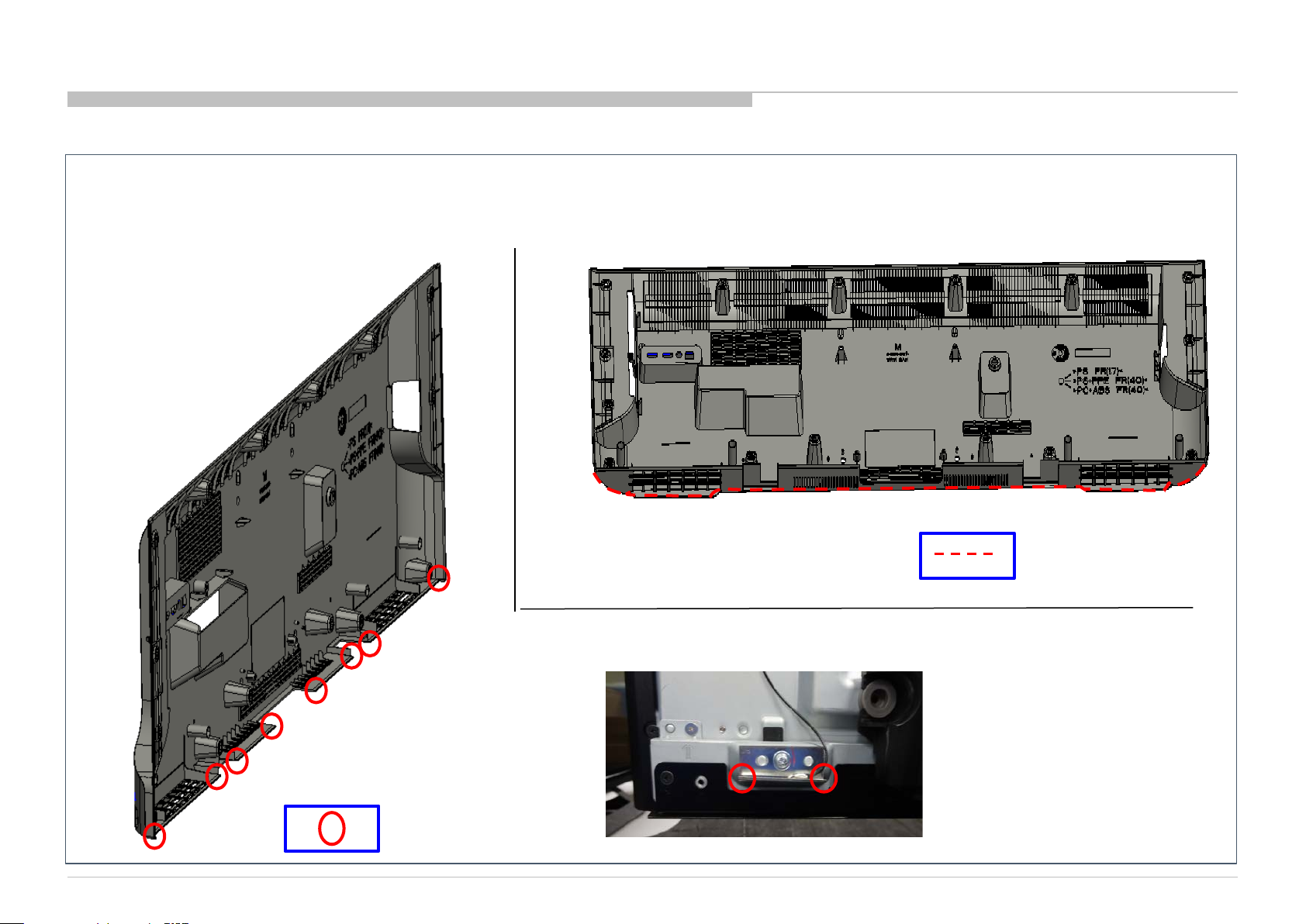
1-1-4. KF: Sharp Edge Infor m ation
Caution point:
Please wear glove while rem oving rear c over to avoi d sharp edge at bottom area as shown i n figure below.
Sharp edge area
Sharp edge corner
9
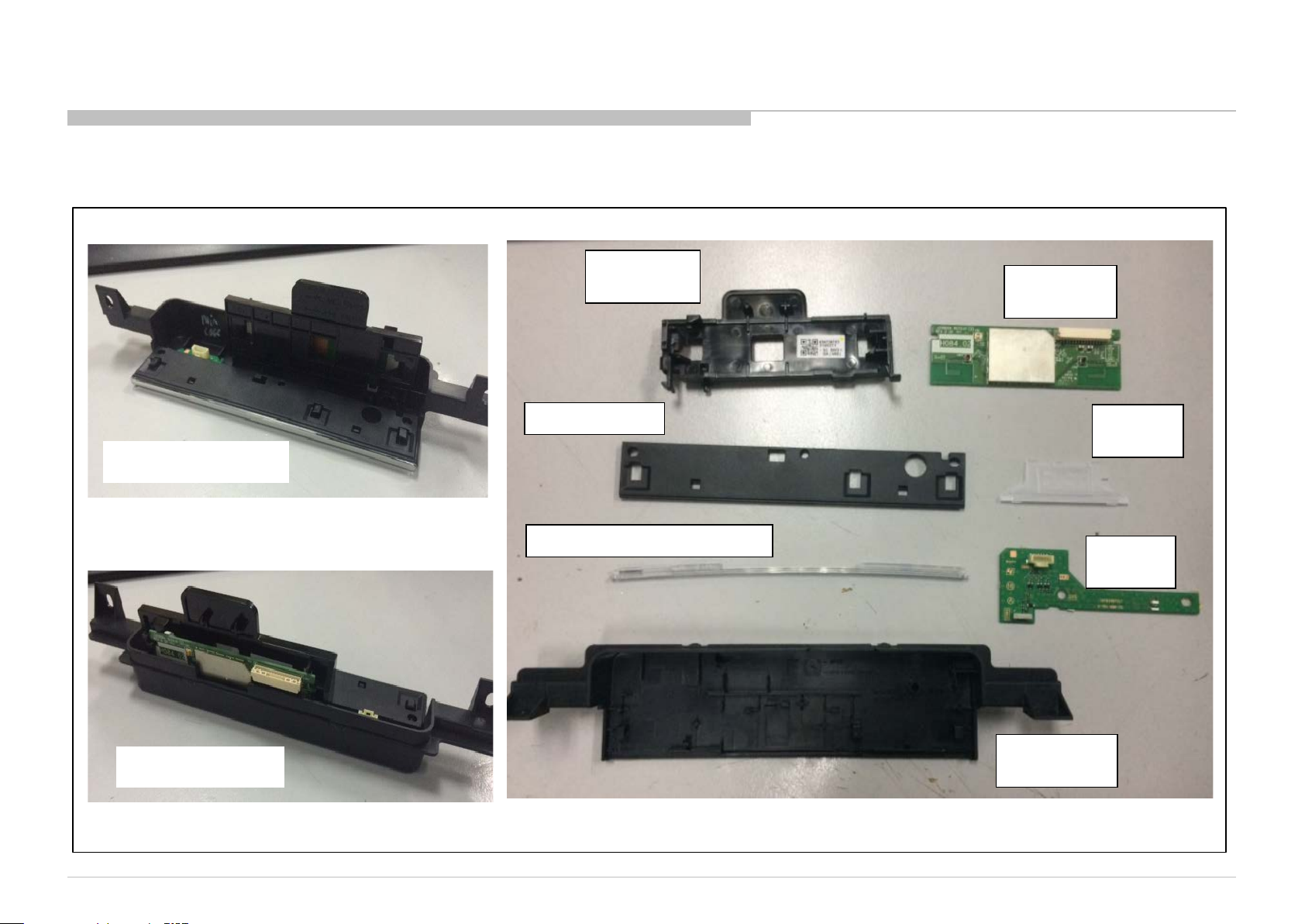
1-2. Procedure To Disassemble Sm ar t Cor e
1-2-1. General
FRONT VIEW
BRACKET,
WIFI
COVER, TOP
PANEL, ORNAM ENT
WIFI
BOARD
LIGHT,
GUIDE
HSC3
board
BACK VIEW
CASE,
BOTTOM
10
1-2. Procedure To Disassemble Sm ar t Cor e
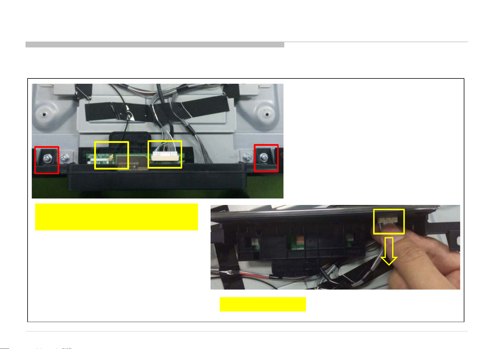
1-2-2. Disassemble Smart Core from Set
1. Remove harness in yellow box
2. Remove screw in red box
3. Remove harness
11
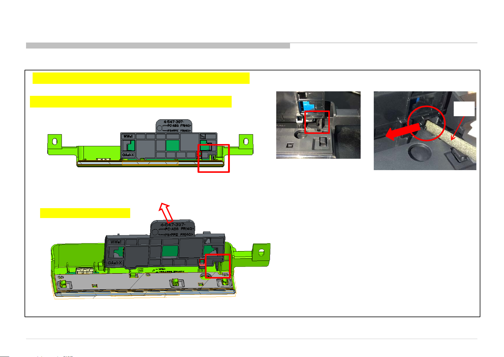
1-2-3. Disassemble Brack et WiFi
*Remark: Apply for Smart Core (F), Smart Core (FC), Smart Core (H) only
1. Push hook ac cor ding to ar row dire ct ion us ing jig
2. Pull Bracket Wifi at the
same time
*Recommended size of jig
[Jig not supplied ]
Width < 5mm, thickness < 2mm
Jig
12
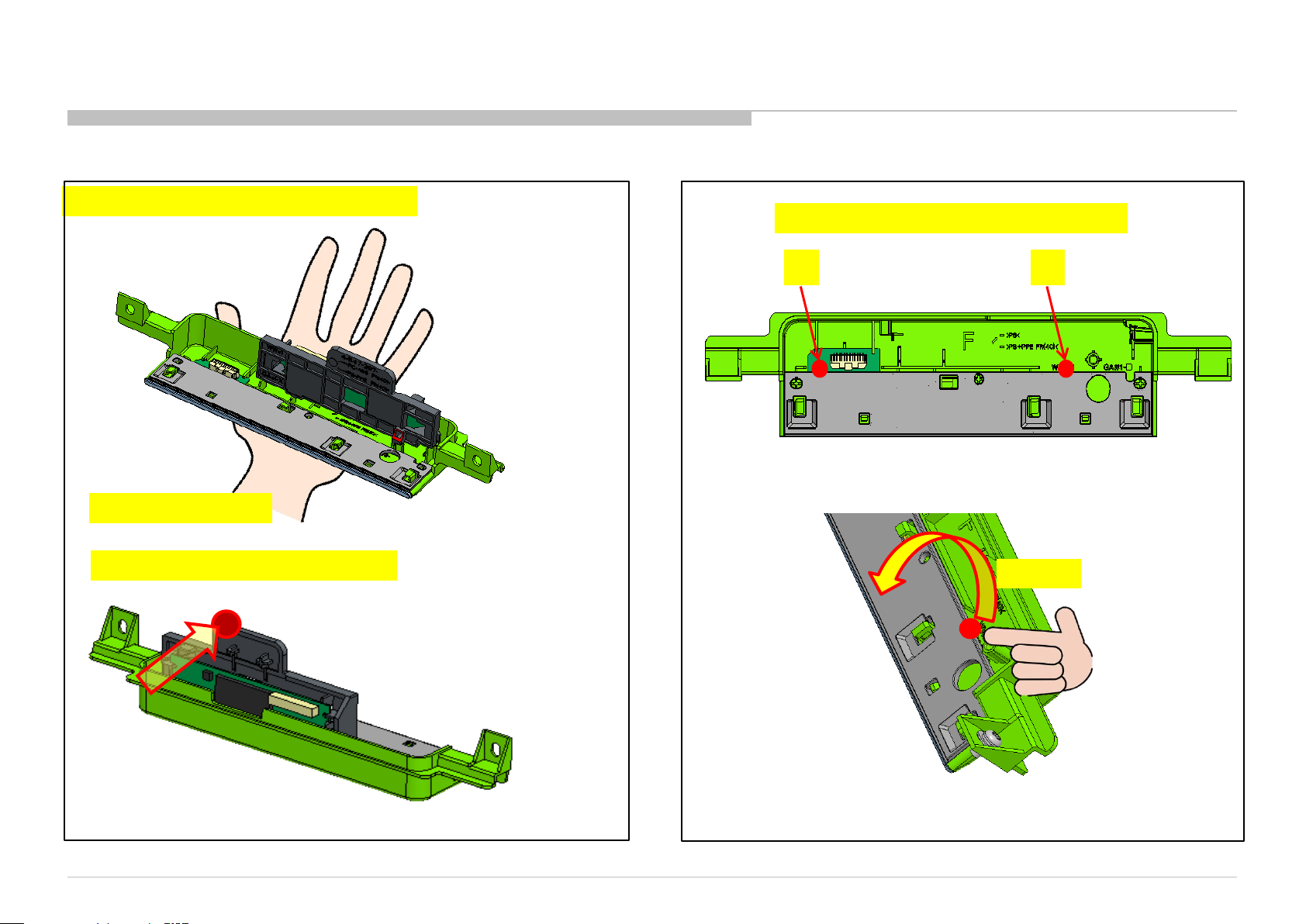
1-2-4. Disassemble Brack et WiFi
*Remark: Apply for Smart Core (H65) only
1. Hold Smart Core
1-2-5. Disassemble Cover Top
Pull up t he c ov e r top by the following order
① ②
2. Push here to front from back side
Pull up
13
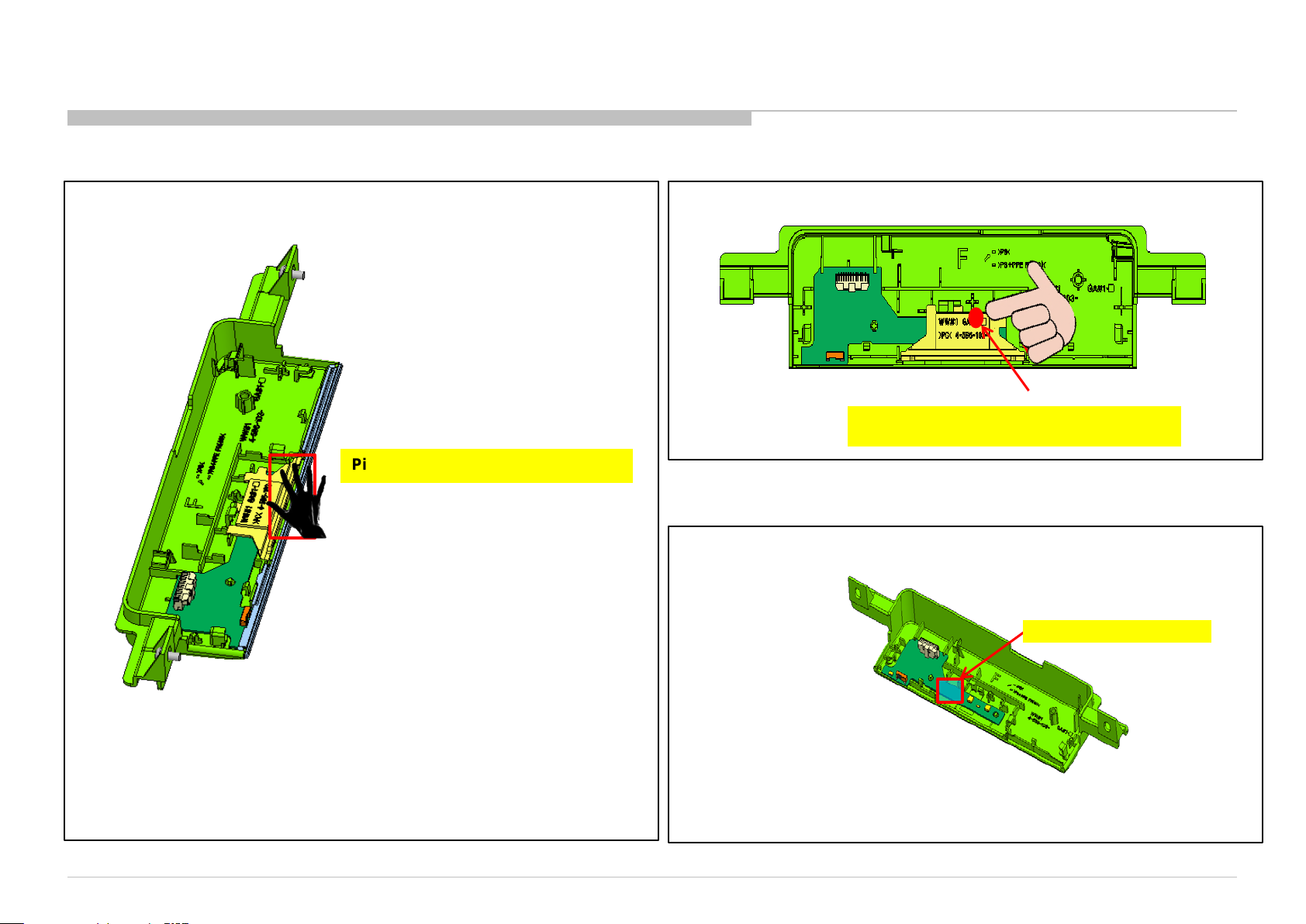
1-2-6. Disassemble Panel Ornam ent
Pick up Panel Ornament
1-2-7. Disassemble Guide Light
Pull out with index finger
1-2-8. Disassemble H board
Hold this area and
pick up H boa r d
14
SECTION 2
DIAGRAMS
2-1.CIRCUIT BOARD LOCATION
1. XBR-43*
SWITCH
UNIT
LD1_43 ASSY
3. XBR-55*
Smart Core
BFX_ASSY
2. XBR-49*
SWITCH
UNIT
LD1 49 ASSY
Smart Core
SMART CORE BLOCK
BFX_ ASSY
SWITCH
UNIT
GL71_ASSY
Smart Core
BFX ASSY
WLAN/BT MODULE
HSC3 MOUNT
15
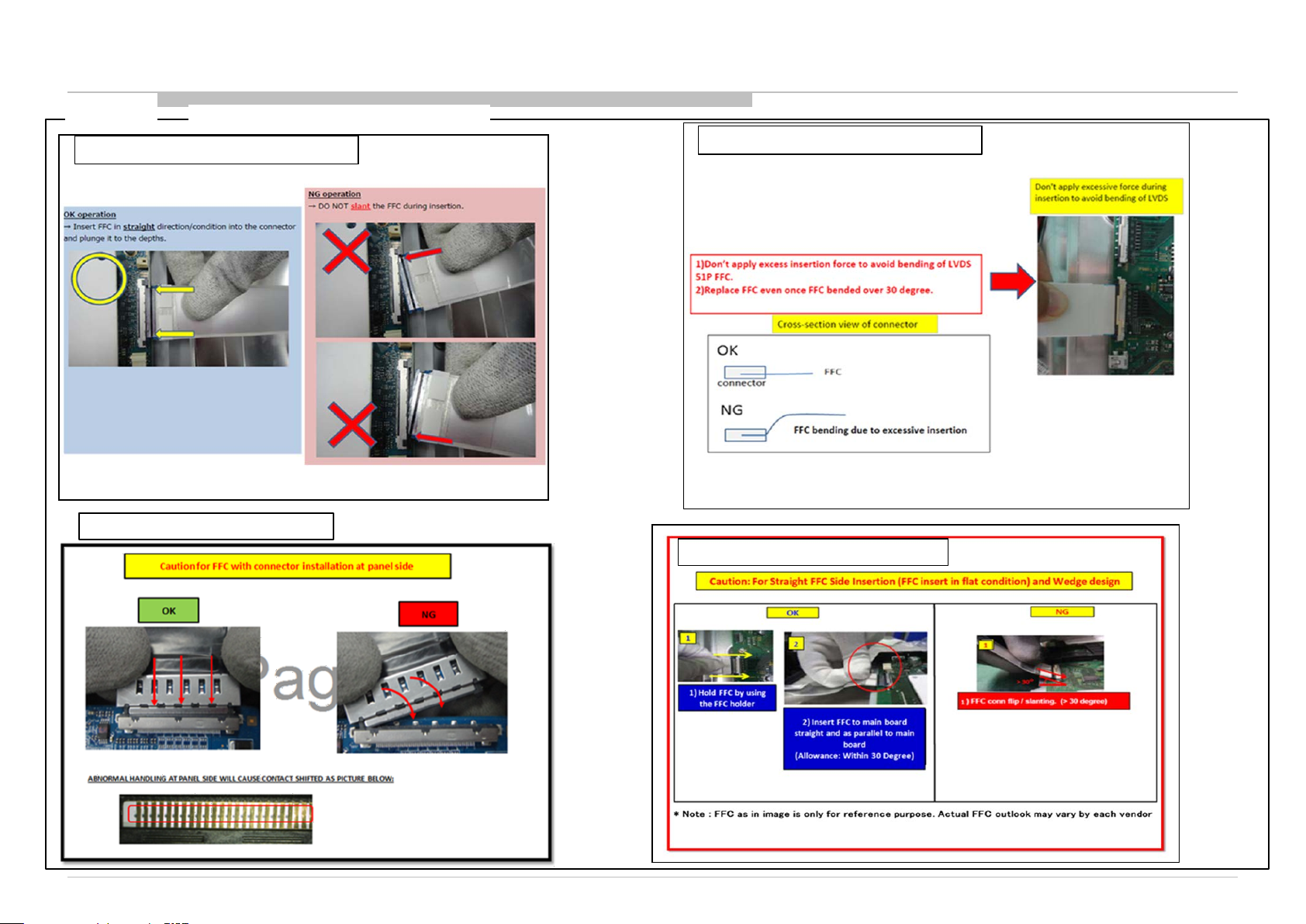
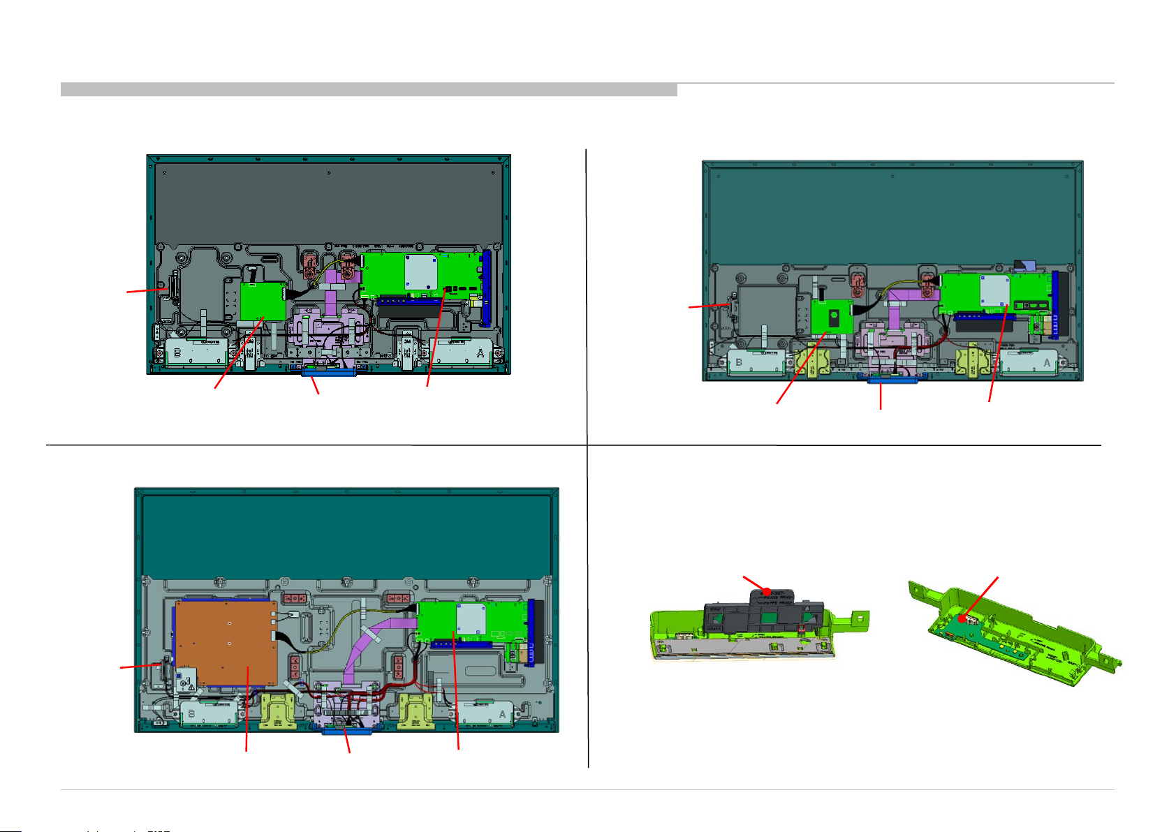
2-2. Wire Dressing
Caution
INSERT CONNECTOR INFORMATION 1
INSERT CONNECTOR INFORMATION 3
FLEXIBLE FLAT CABLE 51P (INSERTION)
INSERT CONNECTOR INFORMATION 2
INSERT CONNECTOR INFORMATION 4
16
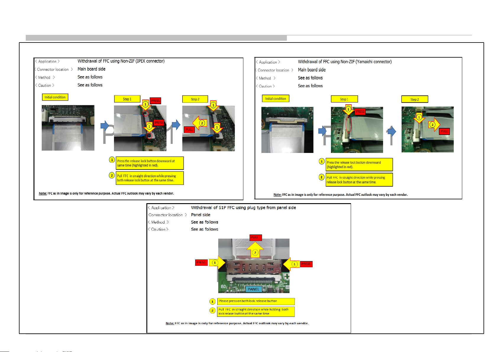
FLEXIBLE FLAT CABLE 51P (WITHDRAWAL)
17
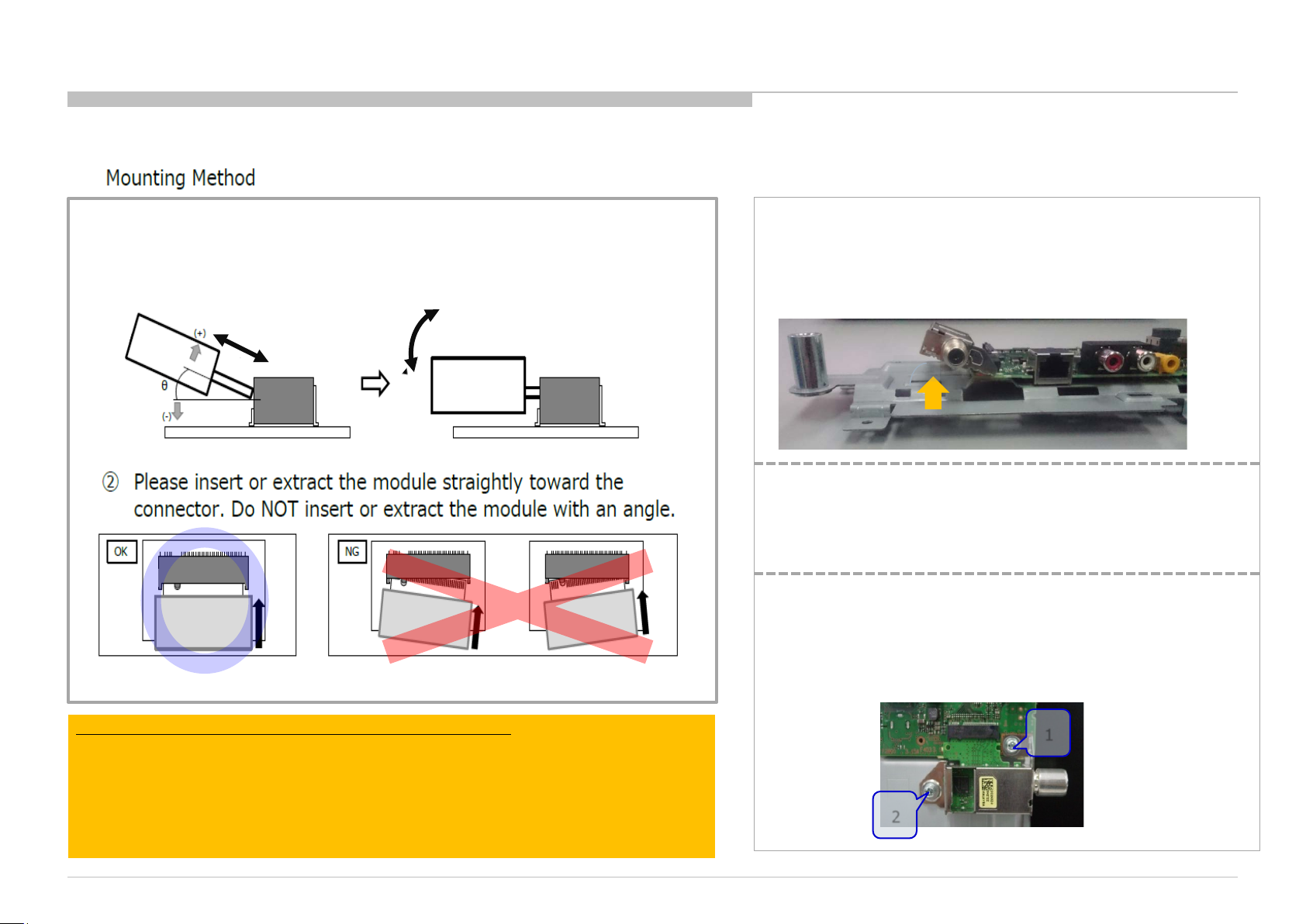
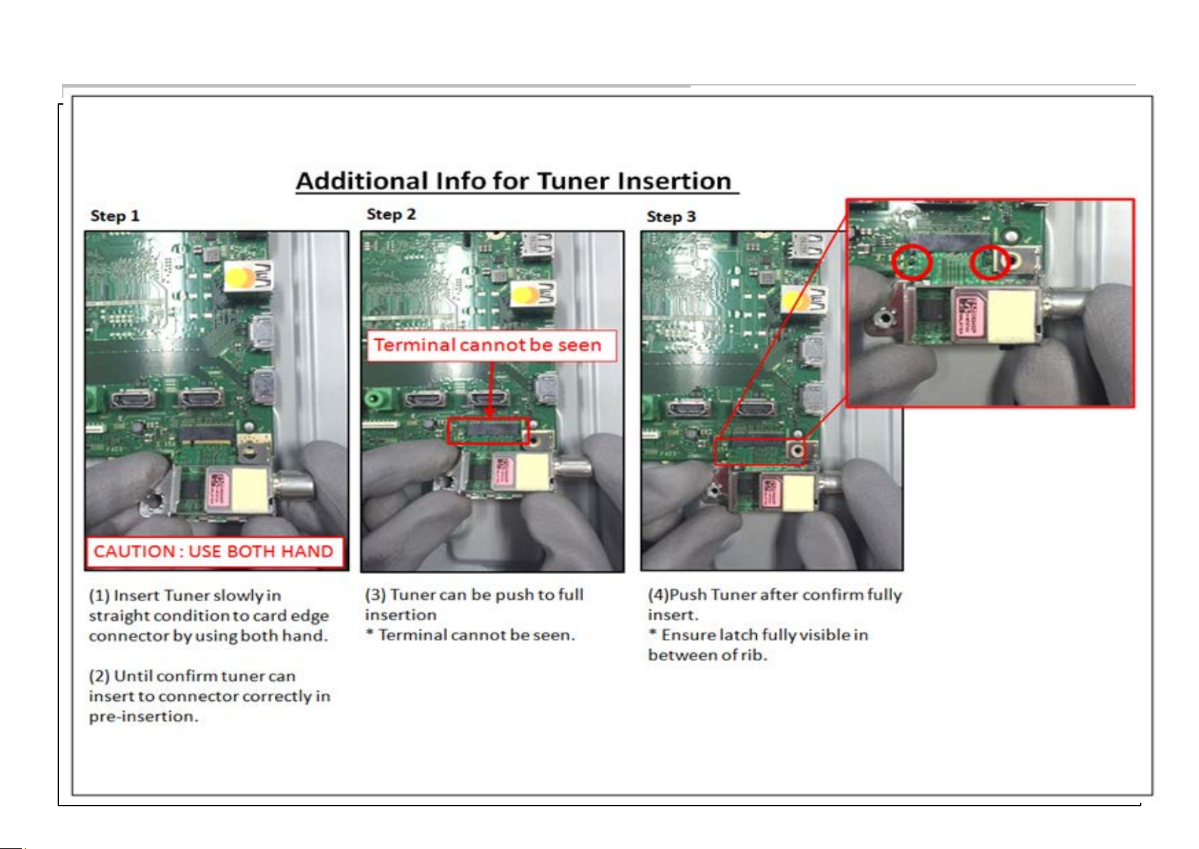
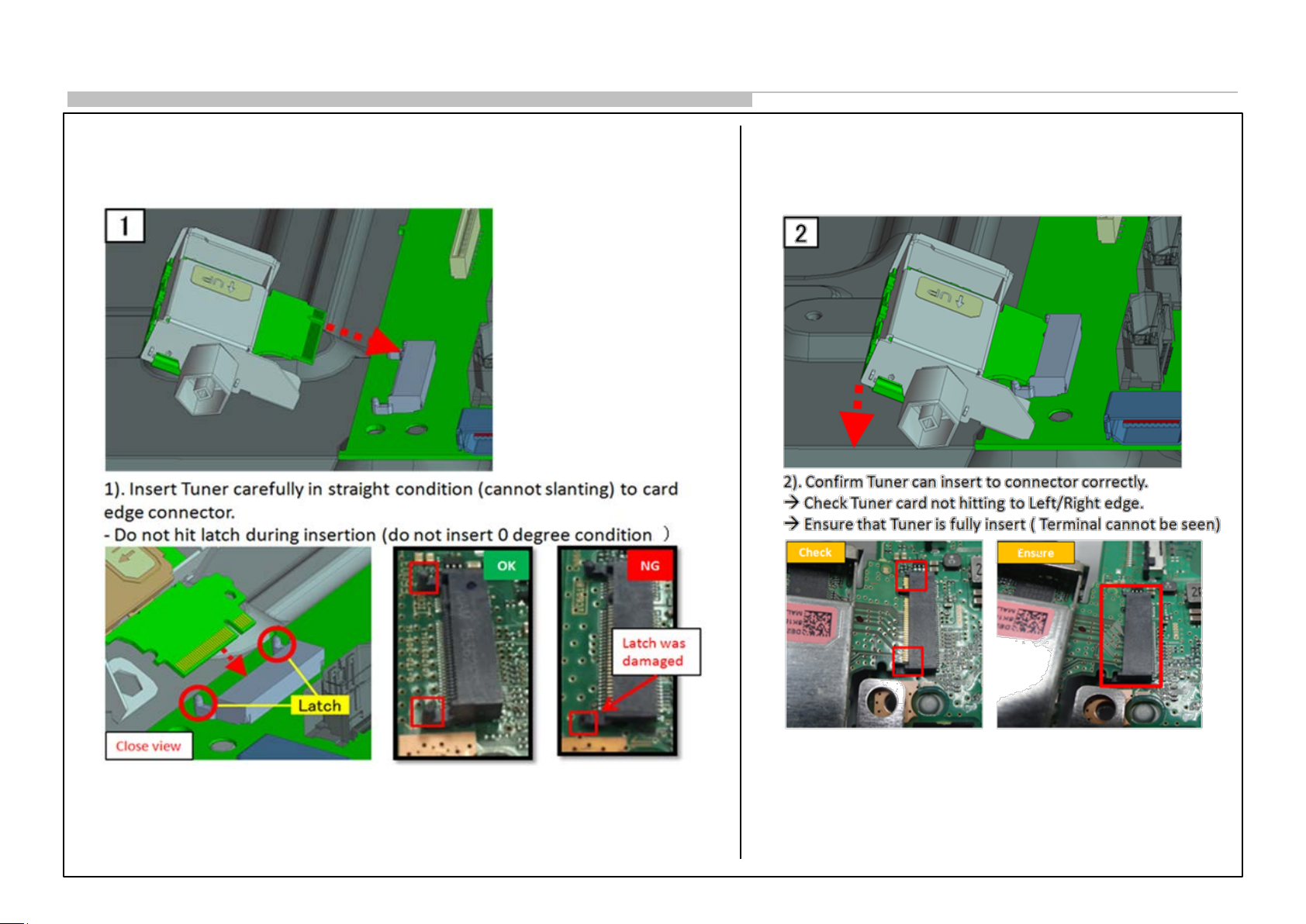
Solder-less tuner replacement procedure
① The insertion & extraction angle of the module is permitted to
specified degree for connec tor
θ≒20°
Push down to screw.
For removing Tuner Module,
In the case of small type Tuner module.
After un screwed, Automatically the Module
will float to c orrect degree.
So please extract it with keeping this degree.
20°
Please c o nfirms whether no dust a nd no bend o n
terminal of connecter(CN2800) and card-edge
connecter
Service manual operation (agreed by service member):
Not using insertion jig. Due quantity not many as production.
SC can control by:
1) Issue service manual for WW ASC.
2) Give training/lecture how to assemble tuner. Will be handle by SOEM
service
Attachment order of screw.
1. Side of antenna ter minal (W/BFX board ).
2. Rear side of Tuner module.
1
2
18
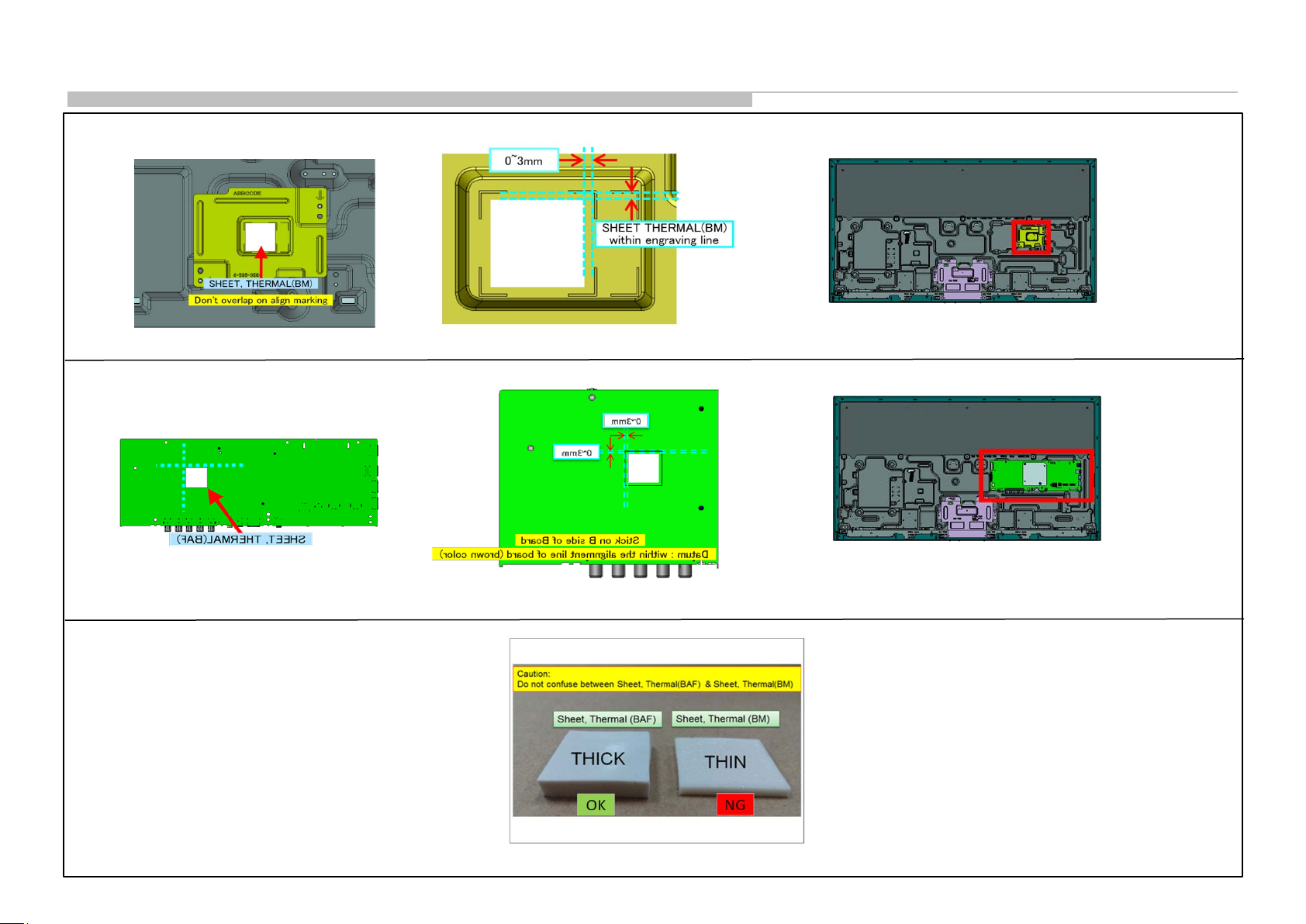
2-2. Wire Dressing
SHEET, THERMAL(BM) Information
SHEET, THERMAL (BAF) Information
19
2-2. Wire Dressing
UNIVERSAL SIL-TU INFOR MATION 1
20
2-2. Wire Dressing
UNIVERSAL SIL-TU INFOR MATION 2
UNIVERSAL SIL-TU INFOR MATION 3
21
 Loading...