

Page 1
3-243-056-22(1)
Media Center/
Receiver
Installation/Connections
安裝連接
Notice to dealers and installers
Please return this manual to the customer after the installation is completed.
經銷商和安裝者請注意
請在安裝完成後把本手冊交還給用戶。
GB
CT
XAV-7W
© 2002 Sony Corporation
Page 2

Precautions
Unit is designed for negative ground
12 V DC systems only
The unit cannot be used in trucks or other cars
with 24 V systems. Otherwise, there is a risk of fire
and damage.
Do not disassemble or remodel the
unit
This can cause electric shock, personal injury or
fire. Do not connect any other system’s power
supply cord to this unit’s power supply cord
directly. If you are in any doubt about the safe
installation of this unit, please consult your nearest
Sony dealer.
Do not install in locations which
interfere with airbag operation
Otherwise there is a risk of accidents and injury.
Use only the specified fuse
When replacing the fuse, be sure to use only a fuse
of the same rating (ampere rating). Otherwise
there is a risk of fire.
On safety
Comply with the Traffic Laws in your country.
Do not block ventilation
If the unit is placed under the floor carpet, floor
mat, or otherwise covered, the ventilation
openings and heat sink cannot provide sufficient
cooling, leading to overheating and the risk of fire
or serious accidents.
Cautions
• Do not get the wires under a screw, or caught in
moving parts (e.g. seat railing).
• Before making connections, turn the car ignition
off to avoid short circuits.
• Connect the yellow and red power input leads
only after all other leads have been connected.
• Run all ground wires to a common ground
point.
• Be sure to insulate any loose unconnected wires
with electrical tape for safety.
Notes on the power supply cord (yellow)
• When connecting this unit in combination with
other stereo components, the connected car
circuit’s rating must be higher than the sum of
each component’s fuse.
• When no car circuits are rated high enough,
connect the unit directly to the battery.
2
Page 3

Table of Contents
Precautions .................................................................................................................... 2
Parts List ........................................................................................................................ 4
1 Installing the Main Unit .......................................................................................... 5
Before installation................................................................................................................. 5
Installation procedure..........................................................................................................7
Installing the connection box XA-114................................................................................ 9
Hooking up the connection box ......................................................................................... 9
2 Main Unit Connections.......................................................................................... 10
Connection Example ................................................................................................... 11
Connecting Information ............................................................................................. 13
Using the tap ....................................................................................................................... 13
Connecting the parking cord ............................................................................................ 13
3 Car Systems Connections ...................................................................................... 14
4 After Installation and Connections ...................................................................... 16
Removing the Front Panel Plate ................................................................................ 17
3
Page 4
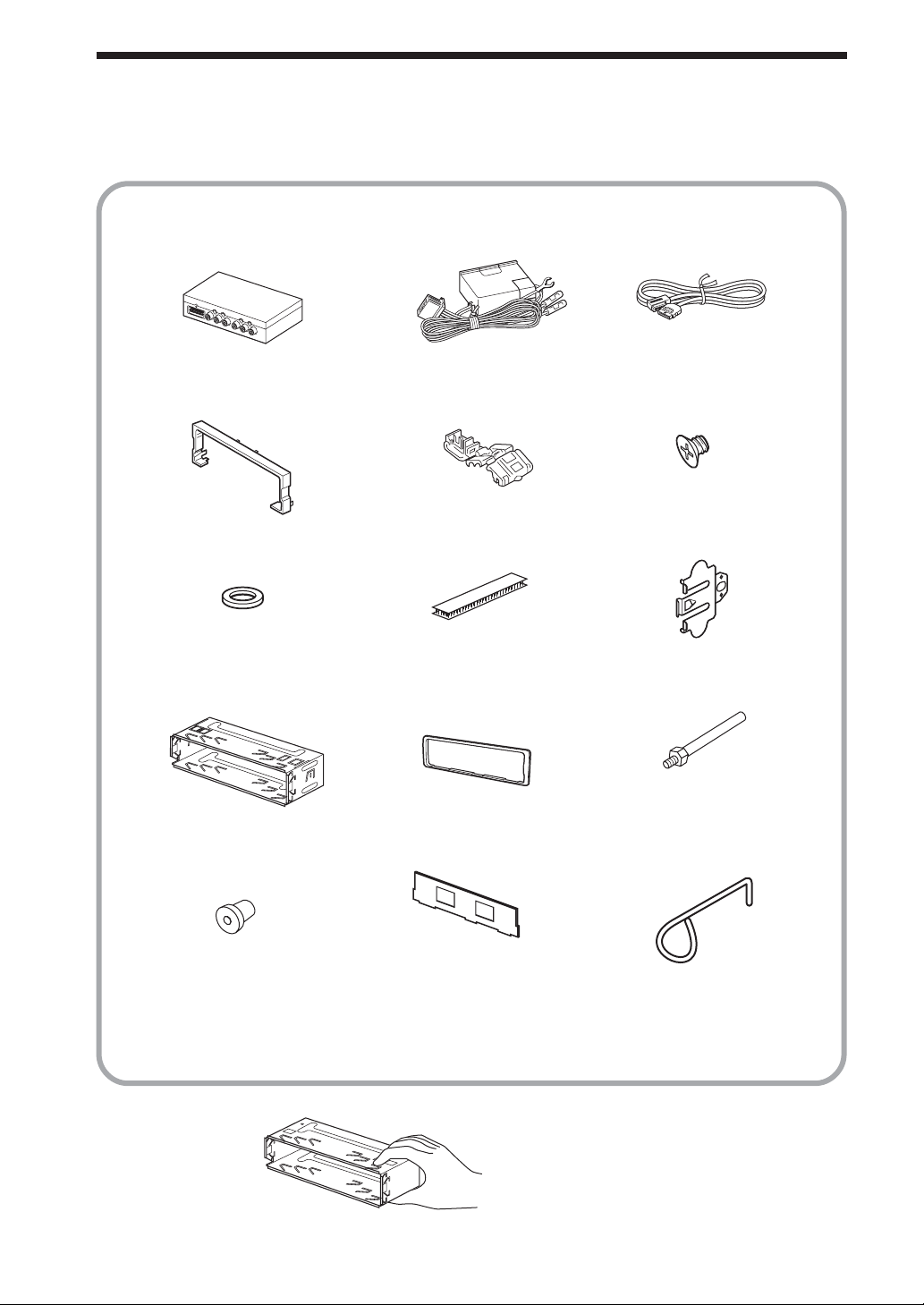
Parts List
The numbers in the list are keyed to those in the instructions.
12 3
*1
4
78 9
×2
q; qa qs
qd qf qg
56
*2
2.5 m
×4
×2
*1Packed while being fixed to the main unit.
*2 Use this to replace the fuse or dismount the unit.
Refer to the Operating Instructions for details.
CAUTION
Handle the bracket
q; carefully to avoid
injuring your fingers.
4
Page 5
1 Installing the Main Unit
Installation angle
The unit should be installed within an
angle of 25 degrees from horizontal. If
this angle is exceeded, the monitor may
not open up or retract properly.
Note
Keep the units and connection cables
apart.
The Media Center main unit and the
connection box 1 should not be in close
proximity.
Before installation
This unit is designed to be completely safe, but if not installed
correctly, it can cause accidents. Be sure to verify the following
points before installation.
Install the main unit to the in-dash location, and the connection
box under the navigator’s seat, etc.
• If the monitor in the opened position is close to a airconditioning outlet, the outlet should be closed.
• Install the unit so that the monitor when opened up will not
block access to the hazard switch or other important controls.
• Do not install the unit (monitor) in locations which may be
subject to excessively low or high temperatures. (Otherwise the
unit may be deformed and the LCD may be damaged.)
Exposure to direct sunlight can also lead to high temperatures
and should be avoided.
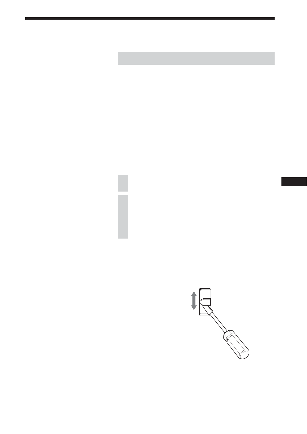
Selecting the installation location
Set the ignition key to OFF or remove it.
1
Place the units in their intended mounting
2
locations to check the cable length and monitor
installation conditions.
Frequency select switch
The AM (FM) tuning interval is factory-set to the 9 k (50 k)
position. If the frequency allocation system of your country is
based on 10 kHz (200 kHz) interval, set the switch on the bottom
of the unit to the 10 k (200 k) position before making connections.
FM 200k AM 10k
FM 50k AM 9k
5
Page 6
Note
If the installation dimensions shown at
right are not observed, the monitor may
not open up smoothly. If this happens,
check the installation once more and
modify the cluster panel where the
dimension requirements are not met. For
some car models, a separately available
mounting kit may be required.
(For details, please consult your dealer.)
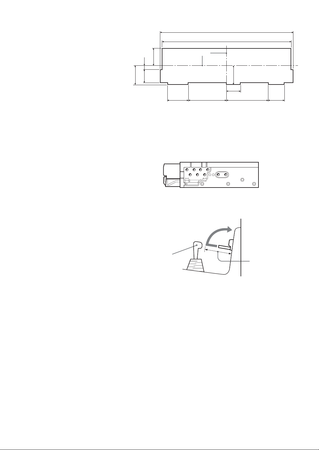
Cluster panel dimensions
175.4
171
Center line
22.5
6.2
25.5
17.3
33.6 44.7 55.7 20.6
25
18
Installation procedure precautions
• Perform the installation carefully. Dropping the unit or
otherwise subjecting it to strong impact or force may deform
the chassis, resulting in failure of the monitor loading
mechanism or other defects.
T/N T/N
N
N
TT
T
N
T/N
Unit: mm
•To allow for proper opening and closing of the monitor, there
must be a clearance of at least 147 mm between the closest
position of the shift lever and the mounting surface for the unit.
Shift lever
At least 147 mm
from mounting
surface
• In some cases, the shift lever may touch the monitor when
moved to a certain position. Make sure that there is no
obstruction to driving operations.
• When installing this unit together with other car audio
equipment (single DIN slot size) in a stacked configuration,
install the Media Center main unit on top.
6
Page 7
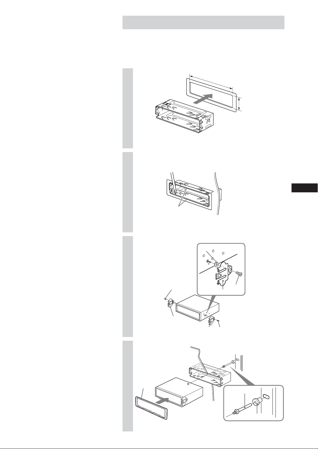
Installation procedure
Mounting example
When installing this unit, be sure to close the monitor of the unit.
If the monitor is opened while installing and given too much
force, it may cause a malfunction.
1
2
3
182 mm
53 mm
q;
Bend these claws outward
for a tight fit, if necessary.
7
4
qa
6
9
q;
9
9
6
Dashboard
6
Fire wall
qs
qd
7
Page 8
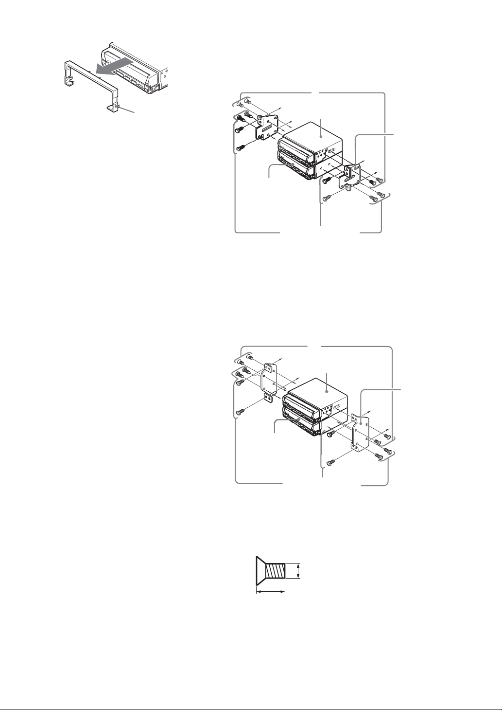
When removing front panel plate
Toyota cars (illustration shows an example for a Toyota car)
Align the brackets of the factory-installed car stereo with the
mounting holes marked “T” on the side of the Media Center main
unit, and use the supplied screws to fasten the brackets. For
Toyota cars, the supplied screws 6 should be used.
6
Front panel
plate 4
Do not throw away the front panel plate,
since it will be needed when you change
the car you install the unit.
For details, see “Removing the Front
Panel Plate”. (page 17).
Note
• Do not press the front panel buttons of
the unit during installation and do not
apply strong force.
• Do not place any objects on top of the
unit.
XAV-7W
Bracket of
factory-installed
car stereo
CSX-V58MP
(optional)
Screws of factoryinstalled car stereo
bracket
Nissan cars
Align the brackets of the factory-installed car stereo with the
mounting holes marked “N” on the side of the Media Center
main unit, and use the supplied pan-head screws 6 to fasten the
brackets.
6
XAV-7W
Bracket of
factory-installed
car stereo
CSX-V58MP
(optional)
Screws of factoryinstalled car stereo
bracket
* Be sure to use only the supplied pan-head screws 6 for
installation. If any other screws are used, make sure they
conform to the requirements shown below.
Using longer screws can cause internal damage to the unit.
5 mm
6 mm
Damage can also occur if the screws are used directly on the
unit without the brackets of the factory-installed car stereo.
8
Page 9
Note
• Ensure that the mounting surface is
clean.
• Do not install the connection box
- in locations subject to high
temperatures
- in locations subject to direct sunlight,
warm air from heater outlets, or
other locations that can get hot.
• When attaching the hook-and-loop
fastener to the bottom of the connection
box, do not cover the model name plate
in the center.
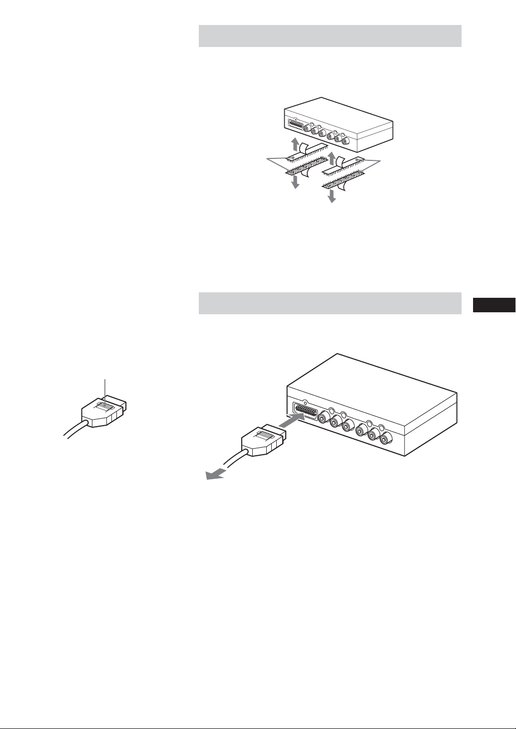
Installing the connection box XA-114
Cut off the required length of hook-and-loop fastener 8 and fix
the connection box 1 on the carpet or similar.
Hook-and-loop
fastener 8
On installation surface
Hook-and-loop
fastener 8
Hooking up the connection box
Refer also to the section “3 Car Systems Connections” (page 14 -
15).
Use of connectors
Insert until the connector clicks into
place. To remove, press here and pull out.
Main unit/connection
box interconnect 3
To Media Center main unit
Insert 3 until a click is heard.
9
Page 10
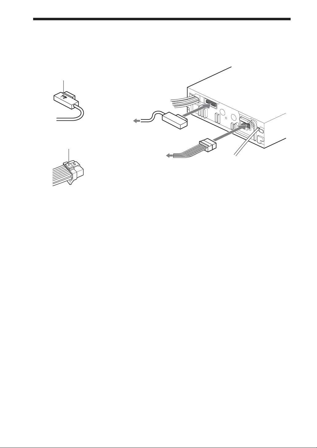
2 Main Unit Connections
Refer also to the section “3 Car Systems Connections” (page 14 -
15).
Use of connectors
Insert until the connector clicks into
place. To remove, press here and pull
out.
To connection
box
Main unit/
Insert until the connector clicks into
place. To remove, press here and pull
out.
connection box
interconnect 3
Insert 2 and 3 until a click is heard.
Power supply leads 2
(for main unit)
10
Page 11
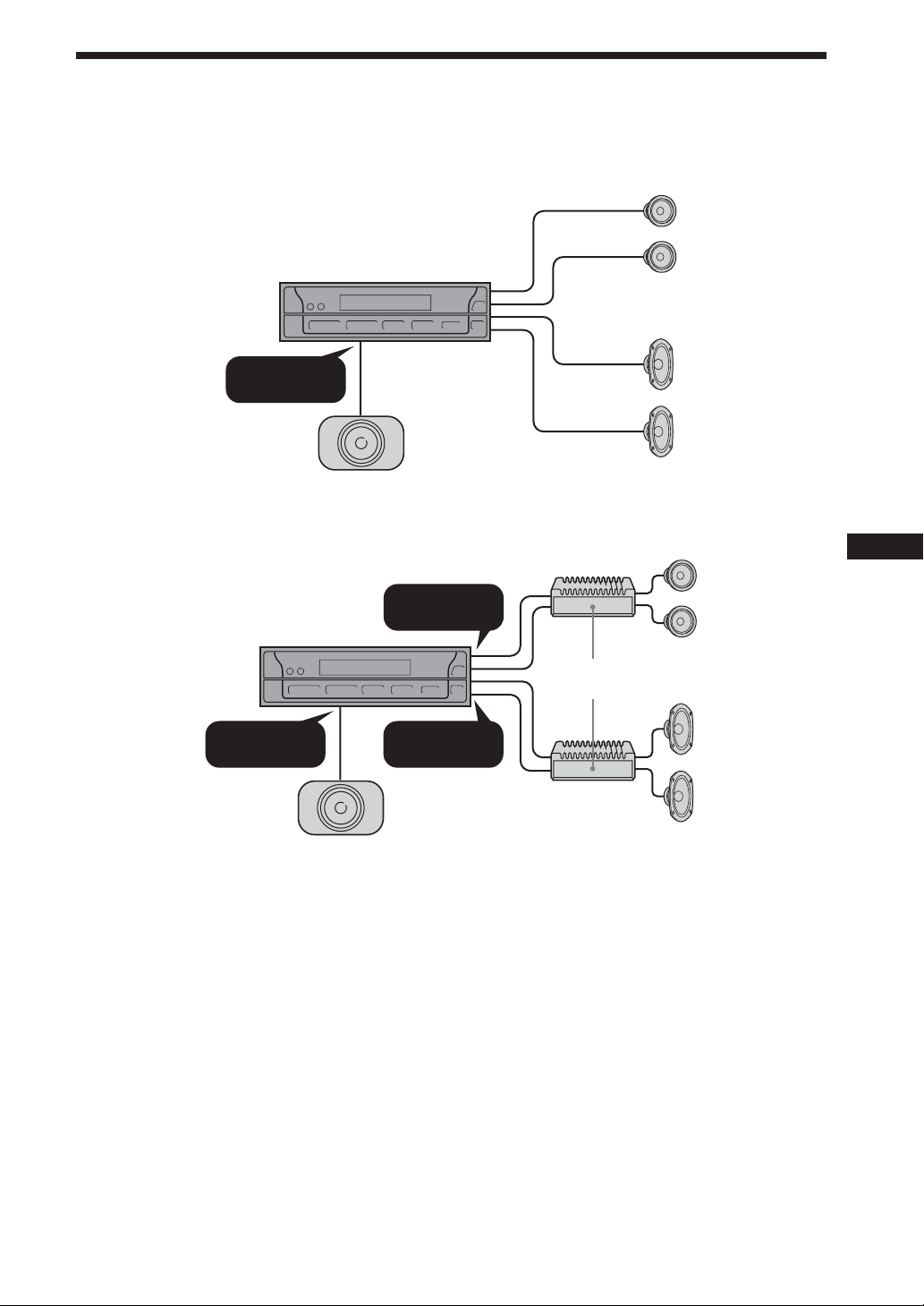
Connection Example
For details, see the section “3 Car Systems Connections” (page 14 - 15). Be sure to refer also to the
documentation for all other components in the system.
Speaker connections
Front speakers
Media Center
main unit
SUB WOOFER
OUT(MONO)
Active subwoofer
(optional)
(optional)
Rear speakers
(optional)
FRONT AUDIO
Media Center
main unit
SUB WOOFER
OUT(MONO)
Notes
• Be sure to connect the ground cord before connecting the amplifier.
• If you connect an optional power amplifier and do not use the built-in amplifier, the beep sound will be deactivated.
OUT
Amplifiers
(optional)
REAR AUDIO
OUT
Active subwoofer
(optional)
Front speakers
(optional)
Rear speakers
(optional)
11
Page 12

Connection of separately available accessories
Items except the main unit and the connection box are optionally available.
With Sony bus system TV tuner unit XT-63V (NTSC system)
Media Center
main unit
Without TV tuner unit
CONTROL(OUT)
CONTROL
XAV
CONTROL(OUT)
TV tuner unit
OUTPUT VIDEO IN
INPUT
Connection box
(supplied)
INPUT1/2
Video component
System up video CD/
MP3 player CSX-V58MP,
CD/MD changer, or
Source selector
XA-C30
CONTROL(IN)
INPUT
Monitor
REAR MONITOR OUTPUT
CONTROL(IN)
CD/MD changer, or
Source selector XA-C30
CD/MD changer
INPUT
Media Center
main unit
CONTROL
XAV
OUTPUT VIDEO IN
INPUT
Connection box
(supplied)
INPUT1/2
Video component
Monitor
REAR MONITOR OUTPUT
Tip
For connecting two or more CD/MD changers, the source selector XA-C30 (optional) is necessary.
12
CD/MD changer
Page 13

Connecting Information
For details, see the section “3 Car Systems Connections” (next page).
Using the tap
Notes
• Be sure to connect the power input
cord after all other cords have been
connected.
• If the parking brake switch cord is too
thin, connect the parking cord to the
parking brake switch cord directly
without using the tap.
Attach and fix the tap securely as illustrated.
Tap 5
Connecting the parking cord
Be sure to connect the parking cord (Light green) to the parking
brake switch cord. The mounting position of the parking brake
switch cord depends on your car. Refer to the system connection
diagram below and consult your car dealer or your nearest Sony
dealer for further details.
Parking brake switch
cord
Parking cord
(Light green)
Battery power
Parking brake
warning light
Parking brake
switch cord
Tap 5
Body earth
Parking cord
(Light green)
Media Center
main unit
Parking brake switch
Parking brake switch cord
Foot brake type
Hand brake type
Parking brake switch cord
13
Page 14

3 Car Systems Connections
Refer also to the documentation for all other components in the system.
Also see “Connecting Information” on page 13.
• Components listed here except for supplied accessories are available separately. When connecting such
components, be sure to also refer to their documentation.
For specifications and other information on separately available components, contact your dealer.
Prevention of accidents caused by short-circuits
To prevent the risk of accidents caused by short-circuits, connect the power supply leads (red and yellow)
only after all other wiring has been completed, and only with the ignition key in the OFF position.
Otherwise, accidental short-circuiting can lead to electric shock and to serious damage.
When a fuse has blown, check the wiring and locate the cause of the problem before replacing the fuse.
When replacing the fuse, be sure to use only a fuse of the same rating (ampere rating). Using a different
fuse or bridging the contacts with wire is highly dangerous and can lead to serious damage.
Make sure to connect all of the following leads.
Otherwise there is a risk of electric shock, damage to the equipment, or malfunction.
• Connect light green lead to parking brake switch lead of car.
• Connect yellow lead to battery power supply of car.
• Connect red lead to accessory power supply of car.
• Connect black lead to metal point on car chassis.
* Do not to mix up the yellow and red leads, as this will cause the memory contents to be lost.
Observe the following precautions.
Otherwise there is a risk of electric shock, damage to the equipment, or malfunction.
• Cover unused connectors with electrician’s tape to prevent accidental contact.
• Route FM/AM antenna cable, bus cable, RCA interconnects, and power supply leads as far apart from
each other as possible, to prevent noise interference.
• Always grasp the connector and do not pull the cable when disconnecting the bus cable or other cables.
Otherwise the cable may become detached.
Note
Install the TV antennas away from the FM/AM antenna.
Notes on the control and power supply leads
• The power antenna control lead (blue) supplies +12 V DC when turn on the tuner.
• When your car has built-in FM/AM antenna in the rear/side glass, connect the power antenna control
lead (blue) or the accessory power input lead (red) to the power terminal of the existing antenna
booster. For details, consult your dealer.
•A power antenna without relay box cannot be used with this unit.
Memory hold connection
When the yellow power input lead is connected, power will always be supplied to the memory circuit
even when the ignition key is turned off.
Notes on speaker connection
• Before connecting the speakers, turn the unit off.
• Use speakers with an impedance of 4 to 8 ohms, and with adequate power handling capacities to avoid
its damage.
• Do not connect the speaker terminals to the car chassis, or connect the terminals of the right speakers
with those of the left speaker.
• Do not connect the ground lead of this unit to the negative (–) terminal of the speaker.
• Do not attempt to connect the speakers in parallel.
• Connect only passive speakers. Connecting active speakers (with built-in amplifiers) to the speaker
terminals may damage the unit.
•To avoid a malfunction, do not use the built-in speaker wires installed in your car if the unit shares a
common negative (–) lead for the right and left speakers.
• Do not connect the unit’s speaker cords to each other.
14
Page 15

Front speakers
(optional)
Rear speakers
(optional)
Active subwoofer
(optional)
Left
Front speakers
(optional)
Right
Left
Rear speakers
(optional)
Right
Amplifiers
(optional)
RCA interconnects
(optional)
RCA interconnects
(optional)
RCA interconnects
(optional)
White
White/black
Gray
Gray/black
Green
Green/black
Purple
Purple/black
Bus cable (5.3 m) (supplied with XT-63V)
RCA interconnects
(5.3 m) (supplied with
XT-63V)
CONTROL
INPUT
Connection
box 1
TV tuner unit
XT-63V
(optional)
XAV
Main unit/
connection box
interconnect 3
Rotary
Commander
RM-X4S
(optional)
Media Center
main unit
From car
antenna
To a metal surface of the car
To the +12 V power terminal which is
energized at all times
To the +12 V power terminal which is
energized in the accessory position of
the ignition key switch
To a car’s illumination signal
*2
Yellow (0.25 m)
*1
Red (0.25 m)
Fuse (10 A)
Power
supply leads
2 (for main
unit)
*1*3
*1
Orange/white (0.25 m)
Light blue (0.25 m)
To ATT (the interface cable of a car
Black (0.45 m)
telephone)
To AMP REMOTE IN of an optional
power amplifier
*4
Blue/white (0.25 m)
Max. supply current 0.3 A
Blue (0.25 m)
To the power antenna control lead or
power supply lead of antenna booster
amplifier
*3*5
Parking brake switch lead of car
Max. supply current 0.1 A
Light green (2 m)
Tap 5
*1Be sure to connect the black ground lead to it first.
*2First connect the black ground lead, then connect the yellow and red power input leads.
*3When your car has built-in FM/AM antenna in the rear/side glass, see “Notes on the control and power
supply leads” (previous page).
*4This connection is only for amplifiers. Connecting any other system may damage the unit.
*5It is not necessary to connect this lead if there is no power antenna or antenna booster, or with a manually-
operated telescopic antenna.
Note on the accessory power input lead (red)
If there is no accessory position, connect to the +12 V power (battery) terminal which is energized at all times.
15
Page 16

4 After Installation and Connections
Start the car’s engine.
1
Verify that the brake lights, other lights, horn, turn
2
indicators, and all other electrical parts operate
normally.
Note
To avoid the possibility of damage, you
should not use a needle or push the
button too strongly.
Use a ball-point pen or similar to push the Reset
3
button on the unit.
Reset button
When you press the Reset button, the system becomes
operative.
Warning when installing in a car without ACC
(accessory) position on the ignition key switch
Be sure to press and hold OFF on the unit for more than two
seconds to turn off the clock display after turning off the
engine.
When you press OFF only momentarily, the clock display does
not turn off and this causes battery wear.
16
Page 17

B
A
Removing the Front Panel Plate
To remove the front panel plate from the unit,
use the following procedure.
Be careful not to pull off the plastic parts.
Front panel plate
Plaque de panneau
avant
Pull the lower side of the front
1
panel plate forward (arrow A), to
open a gap between the front panel
plate and the body of the unit.
Insert a coin and twist to remove
the front panel plate.
Insert a coin or similar thin item in
2
this gap, and twist to remove the
front panel plate.
Be careful not to damage the unit.
Remove in the order left-to-right.
Spreading the lower side of the
3
front panel plate outward (arrow
B), detach the plate from the body.
Note
Be careful not to pull off the plastic parts attached to the
lower side of the unit together with the front panel plate.
17
Page 18

操作前注意事項
本機僅用於負極接地的12V直流系統
本機不能用於使用24V系統的卡車或其他汽車
上。否則,可能會導致火災和損壞。
不要拆卸或改裝本機
這可以引起觸電、人身傷害或火災。不要把其他
系統的電源線和本機電源線直接相連。如果對本機的
安全安裝有疑問,請向最近的Sony經銷商咨詢。
不要在妨礙安全氣囊操作的地方安裝本機
否則,可能會引發事故和人身傷害。
只使用指定的保險絲
更換保險絲時,請務必使用相同規格的保險絲
(電流規格)。否則,可能引起火災。
不要阻塞通風
如果本機放在地毯、地板墊或其他覆蓋物之下,
通風孔和散熱片將不能對本機進行充分冷卻,從而導
致本機過熱,並有發生火災或嚴重事故的危險。
注意
• 不要把電線壓在螺釘下面或夾在移動部件(例如座
位扶手)中。
• 在連接前,請把點火鑰匙轉到off以避免短路。
• 只有連接其他所有導線後,才能連接黃色和紅色電
源輸入導線。
• 把所有地線連到一公共的接地點。
• 為了安全,務必用電工膠帶絕緣任何未連接的電
線。
電源線(黃色)注意事項
• 當本機和其他立體聲部件相連時,連接的汽車電路
額定電流必須大於每一部件保險絲額定電流的總
和。
• 當汽車電路額定電流不夠大時,可直接把本機連到
電池上。
安全方面
請遵守您所在國家的交通法規。
2
Page 19

目錄
操作前注意事項 ............................................................. 2
部件列表 ................................................................... 4
1 安裝主機 ............................................................... 5
安裝之前................................................................ 5
安裝過程................................................................ 7
安裝連接盒XA-114........................................................ 9
連接連接盒.............................................................. 9
2 主機連接 .............................................................. 10
連接示例 .................................................................. 11
連接資訊 .................................................................. 13
使用分接頭............................................................. 13
連接停車線............................................................. 13
3 汽車系統連接 .......................................................... 14
4 安裝和連接以後 ........................................................16
取下前面板板 .............................................................. 17
3
Page 20

部件列表
列表中的號碼和說明書中的號碼相對應。
12 3
*1
4
78 9
×2
q; qa qs
qd
56
*2
qf
qg
2.5 m
×4
×2
*1 當固定到主機上時包扎。
*2 用來更換保險絲或拆卸本機。
詳情請參見使用說明書。
注意
小心處置固定架 q; 以
免弄傷手指。
4
Page 21

1 安裝主機
安裝角度
本機的安裝角度應為水平25度之內。如果超
過這一角度,監視器可能不能正常打開或
收回。
注意
把設備和連接電纜分開。
媒介中心主機和連接盒 1 不要靠得太近。
安裝之前
本機的設計是十分安全的,但如果安裝不正確,可能引起事故。
在安裝前請務必確認下列各點。
把主機安裝到儀表板上。並把連接盒安裝到副駕駛座等下面。
• 如果打開的監視器靠近空調出風口,應關閉出風口。
• 監視器打開時不應妨礙危急開關或其他重要控制部件的使用。
• 不要把本機(監視器)安裝在要經受高溫或低溫的位置(否則,外
殼可能變形,液晶顯示屏可能損壞。)
受到陽光直射也會導致高溫,應該加以避免。
選擇安裝位置
把點火鑰匙設為OFF或取下。
1
把設備放入計劃好的安裝位置,檢查電纜長度和監視器安
2
裝條件。
頻率選擇開關
AM(FM)調諧間隔工廠預設為9k(50k)位置。如果您所在國家的頻
率分配系統是基於10kHz(200kHz)間隔的,在連接前請把本機底部的
開關設到10k(200k)位置。
FM 200k AM 10k
FM 50k AM 9k
5
Page 22

注意
如果不按照右圖所示的安裝尺寸安裝,監視
器可能不能順利打開。此時,請再次檢查安
裝,修改不滿足尺寸要求的組件面板,對於
某些車型,可能需要另購的安裝套件。
(詳情請向經銷商咨詢。)
組件面板尺寸
22.5
6.2
175.4
171
中心線
25.5
17.3
33.6 44.7 55.7 20.6
25
18
(單位︰mm)
安裝前注意事項
• 請仔細進行安裝。摔落本機或使其受到強力衝擊或壓力可能使底座
變形,導致監視器裝載機構故障或其他故障。
T/N T/N
N
N
TT
T
N
T/N
• 要使監視器正確打開和關閉,變速杆最靠近位置和本機安裝表面之
間必須至少有147mm的間隙。
變速杆
離開安裝表面至少
147mm
• 在某些情況下,當變速杆移到某一個位置時,可能和監視器相碰。
請確保這不會妨礙駕駛。
• 當本機和其他汽車音訊設備(單個DIN槽尺寸)一起以堆疊形式安
裝時,請把媒介中心主機安裝在頂部。
6
Page 23

安裝過程
安裝示例
當安裝本機時,務必關閉本機的監視器。
在安裝時如果監視器打開且用力過度,可能發生故障。
1
2
3
182 mm
53 mm
q;
如果需要,請朝外彎曲這些
爪卡以實現緊配合。
7
4
qa
6
9
q;
9
9
6
儀表板
6
防火壁
qs
qd
7
Page 24

當取下前面板板時
前面板板 4
不要丟棄前面板板,因為當安裝本機的汽
車改變時,它會有用。
詳情請參見“取下前面板板”。(第17
頁)。
注意
• 安裝期間不要按本機前面板上的按鈕,不
要用強力。
• 不要在本機頂上放任何物體。
豐田汽車(插圖顯示的是豐田汽車的連接示例)
把工廠安裝的汽車立體聲機架和媒介中心主機側面標有“T”
的安裝孔對準,使用附帶的螺釘安裝機架。對於豐田汽車,請使用
附帶的螺釘 6。
6
XAV-7W
工廠安裝的汽車立
體聲機架
CSX-V58MP
(選購)
工廠安裝的汽車立
體聲機架螺釘
尼桑汽車
把工廠安裝的汽車立體聲機架和媒介中心主機側面標有“N”
的安裝孔對準,使用附帶的盤頭螺釘 6 安裝機架。
6
XAV-7W
工廠安裝的汽車
立體聲機架
CSX-V58MP
(選購)
工廠安裝的汽車立
體聲機架螺釘
* 務必只使用附帶的盤頭螺釘 6 進行安裝。如果使用其他螺釘,
請確保它們符合下圖的要求,使用較長的螺釘可能使本機內部受
損。
5 mm
6 mm
如果螺釘直接裝在本機上而不使用工廠安裝的汽車立體聲機
架,也可能造成損壞。
8
Page 25

注意
• 確保安裝表面是清潔的。
• 不要在高溫處
- 陽光直射位置
- 受加熱器出口熱空氣侵襲或其他受熱位
置安裝連接盒。
• 當把粘扣帶粘到連接盒底部時,請不要覆
蓋中央的型號銘牌。
安裝連接盒XA-114
剪下所需長度的粘扣帶 8,並把連接盒 1 安裝在地毯或類似
物體上。
粘扣帶 8
粘扣帶 8
在安裝表面上
連接連接盒
也請參見“3 汽車系統連接”(第14-15頁)。
使用連接器
插入直到連接器喀嗒一聲到位。要取出,
按此處並拉出。
主機連接盒互連器 3
到媒介中心主機
插入 3 直到聽到喀嗒聲。
9
Page 26

2 主機連接
使用連接器
插入直到連接器喀嗒一聲到位。要取出,請
按此處並拉出。
插入直到連接器喀嗒一聲到位。要取出,請
按此處並拉出。
也請參考“3 汽車系統連接”(第14-15頁)。
到連接盒
主機連接盒互
連器 3
電源線 2(用於主機)
插入 2 和 3 直到聽到喀嗒聲。
10
Page 27

連接示例
詳情參見“3 汽車系統連接”(第14-15頁)。務必也請參考系統中所有其他組件的說明書。
揚聲器連接
前揚聲器(選購)
媒介中心主機
SUB WOOFER
OUT(MONO)
有源超低音揚聲器
(選購)
後揚聲器(選購)
FRONT AUDIO
OUT
媒介中心主機
SUB WOOFER
OUT(MONO)
注意
• 連接放大器前,務必先連接地線。
• 如果連接一選購的電源放大器而不使用內置放大器,將不發出嗶聲。
REAR AUDIO
OUT
有源超低音揚聲器(選購)
前揚聲器(選購)
放大器(選購)
後揚聲器(選購)
11
Page 28

連接另購的附件
除主機和連接盒以外的各項是選購件。
帶Sony總線系統電視調諧器XT-63V(NTSC 制式)
媒介中心主機
不帶電視調諧器
CONTROL(OUT)
CONTROL
XAV
CONTROL(OUT)
電視調諧器
OUTPUT VIDEO IN
INPUT
連接盒(附帶)
INPUT1/2
視訊組件
系統上VCD/MP3播放機
CSX-V58MP,CD/MD換
碟機或設備源選擇器
XA-C30
CONTROL(IN)
INPUT
監視器
REAR MONITOR OUTPUT
CONTROL(IN)
CD/MD換碟機,或設備源
選擇器XA-C30
CD/MD換碟機
OUTPUT VIDEO IN
CONTROL
媒介中心主機
XAV
INPUT
連接盒(附帶)
INPUT1/2
視訊組件
要點
要連接兩個或多個CD/MD換碟機,需要設備源選擇器XA-C30(選購)。
INPUT
監視器
REAR MONITOR OUTPUT
CD/MD換碟機
12
Page 29

連接資訊
詳情參見“3 汽車系統連接”(下一頁)。
注意
• 務必在所有其他電線已連接後再連接電源
輸入線。
• 如果剎車開關導線太細,則不要使用分接
頭,直接把停車線連到剎車開關導線。
使用分接頭
如圖所示牢固地連接並固定分接頭。
剎車開關導線
分接頭 5
停車線(淺綠色)
連接停車線
務必把停車線(淺綠色)連到剎車開關導線上,剎車開關導線的
固定位置和您的汽車有關。進一步的詳情請參見下面的系統連接圖並
向汽車經銷商或最近的Sony經銷商咨詢。
電池電源
剎車警告燈
剎車開關導線
車身接地
分接頭 5
停車線(淺綠色)
媒介中心主機
剎車開關
剎車開關導線
腳剎型
手剎型
剎車開關導線
13
Page 30

3 汽車系統連接
也請參見系統中所有其他組件的說明書。
也請參見第13頁的“連接資訊”。
• 除了隨機附件外,這裡所列的組件需要另購。當連接此類組件時,務必也請參見它們的說明書。
有關另購組件的規格和其他資訊,請和經銷商聯繫。
防止短路引起事故
為了防止短路引起事故,只有在其他線路連接完後才能連接電源線(紅色和黃色),且點火鑰匙必須在
OFF位置。
否則,意外的短路可能引起觸電和嚴重的損壞。
當保險絲熔化時,在更換保險絲之前請先檢查線路並確定問題原因。當更換保險絲時,請務必使用相同
規格的保險絲(電流規格)。使用不同的保險絲或用電線連接是非常危險的,可能引起嚴重的損壞。
務必連接下列所有導線。
否則,可能導致觸電、設備損壞或故障。
• 連接淺綠色導線到汽車的剎車開關導線。
• 連接黃色導線到汽車的電池電源。
• 連接紅色導線到汽車的輔助電源。
• 連接黑色導線到汽車底盤的金屬點上。
* 不要混淆黃色和紅色導線,這將引起記憶體內容丟失。
請遵守下列事先注意事項。
否則,可能引起觸電、設備損壞或故障。
• 用電工膠帶纏好不用的連接器以防意外接觸。
• 使FM/AM天線電纜、總線電纜、RCA互連器和電源線相互之間盡量遠離,以防止噪音干擾。
• 當斷開總線電纜或其他電纜時,必須抓住連接器,不要拉電纜。否則,電纜可能斷開。
注意
使電視天線安裝在遠離FM/AM天線之處。
控制部件和電源線注意事項
• 當打開調諧器時,電源天線控制導線(藍色)提供+12V直流電源。
• 當您的汽車在後側玻璃上有內置FM/AM天線時,請把電源天線控制導線(藍色)或輔助電源線(紅色)連
到現有天線放大器的電源端子上。詳情請向經銷商咨詢。
• 沒有中繼盒的電源天線不能和本機一起使用。
記憶保持連接
當連接黃色電源線時,即使點火鑰匙關閉,也總是向記憶電路供電。
揚聲器連接注意事項
• 在連接揚聲器之前,請關閉本機。
• 使用4到8Ω阻抗的揚聲器,並有足夠的電源處理容量以防損壞。
• 不要把揚聲器端子連到汽車外殼上,或把左右揚聲器的端子相連。
• 不要把本機的地線和揚聲器的負端子 (–) 相連。
• 不要企圖並聯揚聲器。
• 只能連接無源揚聲器。把有源揚聲器(帶內置放大器)連到揚聲器端子可能損壞本機。
• 為避免故障,如果左右揚聲器共用一公共負 (–) 導線,不要使用安裝在汽車裡的內置揚聲器電線。
• 不要相互連接本機的揚聲器電線。
14
Page 31

RCA互連器(選購)
總線電纜 (5.3m)(XT-63V附帶)
前揚聲器(選購)
放大器
(選購)
後揚聲器(選購)
RCA互連器(選購)
有源超低音揚聲器
(選購)
左
前揚聲器(選購)
右
左
後揚聲器(選購)
右
到汽車的金屬表面 *
到+12V電源端子,它隨時供電 *
2
1
到+12V電源端子,它在點火鑰匙開關 *1*
的輔助位置供電
到汽車的照明信號 *
1
到ATT(汽車電話的接口電纜)
到選購的電源放大器的AMP REMOTE IN *
到天線放大器的電源天線控制導線或電源
5
線 *3*
連接汽車的剎車開關導線
RCA互連器(選購)
白色
白色黑色
灰色
灰色黑色
綠色
綠色黑色
紫色
紫色黑色
3
4
電視調諧器
XT-63V(選購)
黑色 (0.45m)
黃色 (0.25m)
紅色 (0.25m)
橙色白色 (0.25m)
淺藍色 (0.25m)
藍色白色 (0.25m)
最大供電電流 0.3A
藍色 (0.25m)
最大供電電流 0.1A
淺綠色 (2m)
分接頭 5
CONTROL
XAV
媒介中心主機
保險絲(10A)
RCA互連器 (5.3m)
(XT-63V附帶)
INPUT
連接盒1
主機連接盒互
連器 3
旋轉主控器RM-X4S
(選購)
從汽車天線
電源線 2
(用於主機)
*1 務必首先連接黑色地線。
*2 首先連接黑色地線,然後連接黃色和紅色電源輸入線。
*3 當您的汽車在後側玻璃上有內置FM/AM天線時,請參見“控制部件和電源線注意事項”(前一頁)。
*4 此連接只能用於放大器,連接任何其他系統可能損壞本機。
*5 如果沒有電源天線或天線放大器,或帶一手動的可伸縮天線時,不需要連接此導線。
輔助電源輸入線(紅色)注意事項
如果沒有輔助位置,請連到+12V電源(電池)端子上,它隨時供電。
15
Page 32

4 安裝和連接以後
啟動汽車引擎。
1
確認剎車燈、其他燈、喇叭、轉向指示燈和所有其他電氣
2
部件工作正常。
注意
為防止損壞,不應使用針或過度用力按按
鈕。
使用圓珠筆或類似物體按本機的重設按鈕。
3
重設按鈕
當按下重設按鈕時,系統可以操作。
當在點火鑰匙開關沒有ACC(輔助)位置的汽車上安裝時的警
告
在關閉引擎後務必按住本機上的OFF按鈕2秒以上以關閉時鐘顯
示。
當只是瞬間按下OFF按鈕時,時鐘顯示不關閉並會引起電池損
耗。
16
Page 33

取下前面板板
B
A
要從本機上取下前面板板,執行下列步驟。
前面板板
向前拉前面板板的底邊(箭頭 A),使
1
前面板板和本機機體之間露出一條縫。
插入一個硬幣並扭轉,取下前面板
板。
當心不要扯下塑料部件。
在此縫中插入一個硬幣或類似的薄物
2
體,並扭轉以取下前面板板。
當心不要損壞本機。
按從左到右的順序取下。
向外側拉伸前面板板的底邊(箭頭
3
B),把板從機體上卸下。
注意
當心不要把本機底面上的塑料部件和前面板板一起拉下。
17
Page 34

18
Page 35

19
Page 36

Sony Corporation Printed in Japan Printed on recycled paper
 Loading...