

Sony WF 930Z Service Manual
SERVICE MANUAL
WF-930Z(BK)
WF-930Z
No. S5630WF930Z//
• In the interests of user-safety the set should be restored to its
original condition and only parts identical to those specified
should be used.
CONTENTS
Page
SPECIFICATIONS ............................................................................................................................................................... 2
VOLTAGE SELECTION .......................................................................................................................................................2
AC POWER SUPPLY CORD AND PLUG............................................................................................................................2
NAMES OF PARTS..............................................................................................................................................................3
FITTING OF DIAL POINTER ...............................................................................................................................................3
DISASSEMBLY ....................................................................................................................................................................4
REMOVING AND REINSTALLING THE MAIN PARTS .......................................................................................................5
ADJUSTMENT .....................................................................................................................................................................6
SCHEMATIC DIAGRAM / WIRING SIDE OF P.W.BOARD .................................................................................................8
NOTES ON SCHEMATIC DIAGRAM.................................................................................................................................12
TYPES OF TRANSISTOR AND LED .................................................................................................................................12
REPLACEMENT PARTS LIST / EXPLODED VIEW
SHARP CORPORATION
WF-930Z
FOR A COMPLETE DESCRIPTION OF THE OPERATION OF THIS UNIT, PLEASE REFER
TO THE OPERATION MANUAL.
SPECIFICATIONS
I
General
Power source: AC 110 - 127/220 - 240 V, 50/60 Hz
DC 12 V ["D" size (UM/SUM - 1, R20 or
HP - 2) battery x 8]
Power consumption: 30 W
Output power: PMPO; 60 W (30 W + 30 W)
(AC operation)
MPO (Max.); 20 W (10 W + 10 W)
(AC operation)
RMS; 10 W (5 W + 5 W)
(DC operation, 10 % T.H.D.)
Input terminal: Mixing microphone; 600 ohms
Output terminal: Headphones; 16 -50 ohms
(recommended; 32 ohms)
Dimensions: Width; 300 mm (11 - 13/16")
Height; 217 mm (8 - 9/16")
Depth; 186 mm (7 - 3/8")
Weight: 2.9 kg (6.4 Ibs.) without batteries
I
Radio section
Frequency range: FM; 88 - 108 MHz
SW1; 2.3 - 7.3 MHz
SW2; 7.3 - 22 MHz
MW; 526.5 - 1,606.5 kHz
I
Tape recorder section
Frequency response: 60 - 12,000 Hz (Normal tape)
Signal/noise ratio: 40 dB (TAPE 1, recording/playback)
55 dB (TAPE 2, playback)
Wow and flutter: 0.15 % (WRMS)
Motor: DC 12 V electric governor
Bias system: AC bias
Erase system: Magnet erase
I
Speaker section
Type: 2 - way type
Speakers: 12 cm (4 - 3/4") free - edge
woofer x 2
Tweeter x 2
Maximum input
power: 10 W
Impedance: 3 ohms
Dimensions: Width; 195 mm (7 - 11/16")
Height; 217 mm (8 - 9/16")
Depth; 189 mm (7 - 1/2")
Weight: 1.2 kg (2.6 Ibs.)/each
Specifications for this model are subject to change without
prior notice.
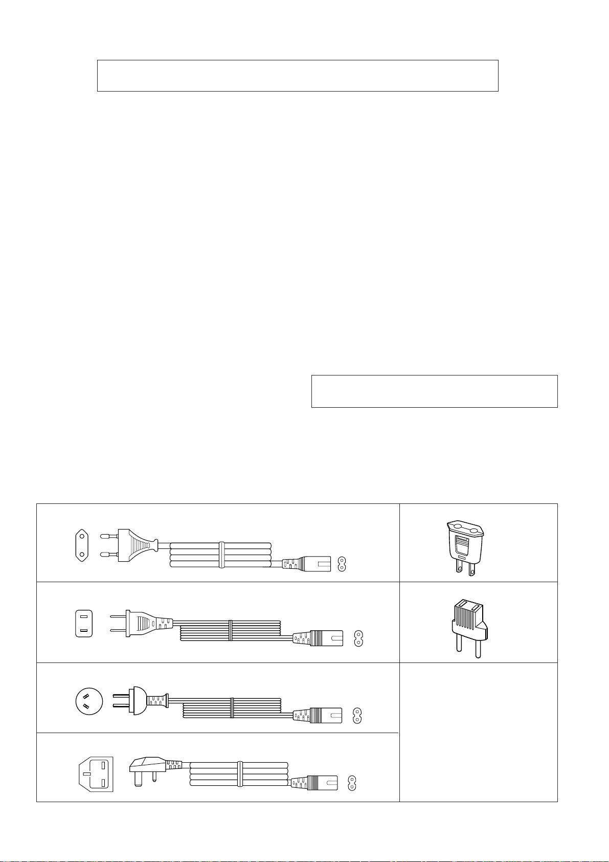
VOLTAGE SELECTION
Before operating the unit on mains, check the preset voltage. If the voltage is different from your local voltage, adjust the voltage as
follows: Slide the AC power supply socket to the visible indication of the side of your local voltage.
AC POWER SUPPLY CORD AND PLUG
9FGS9822020300
9FGS9821620000
9FGS9822020500
QPLGA0250AFZZ
QPLGA0253AFZZ
9FGS9822020400
– 2 –
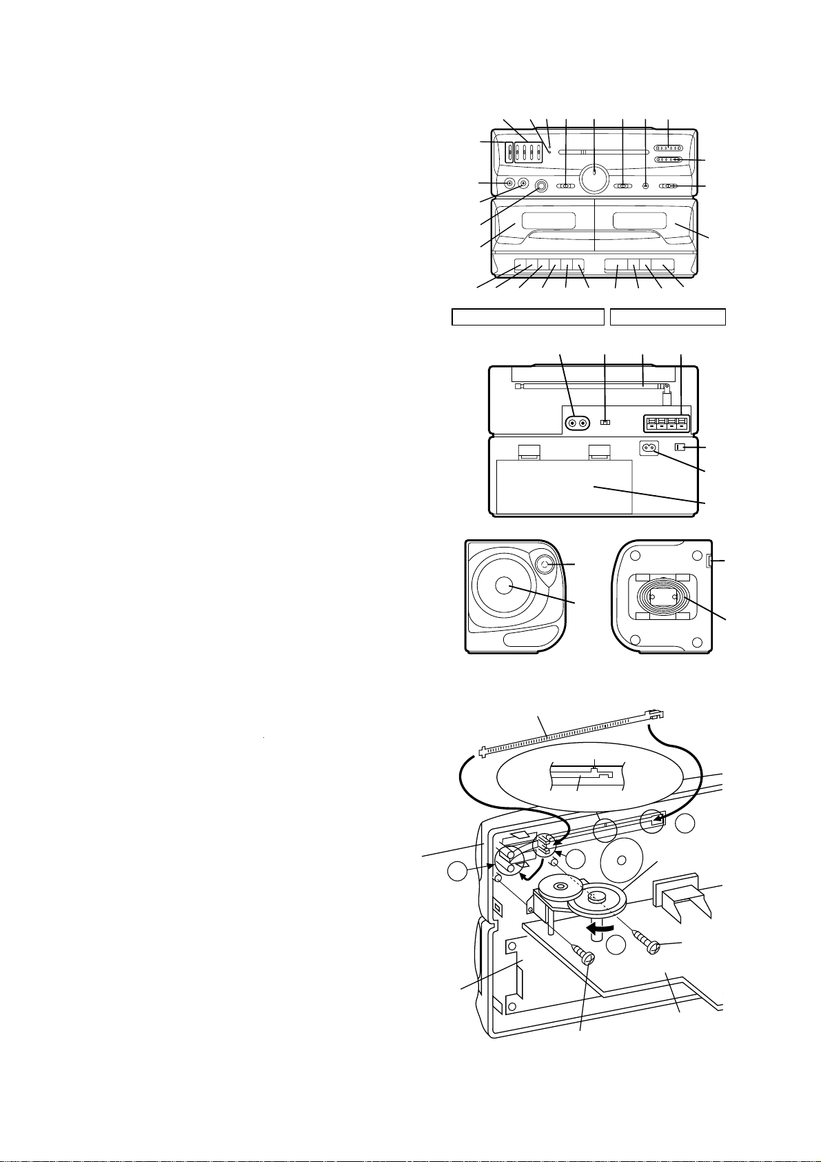
1. Extra Bass Control: X-BASS
2. Graphic Equalizer Controls
3. FM Stereo Indicator
4. Power Indicator
5. Function Selector Switch
6. Volume Control
7. Dubbing Speed/Built-in Microphone Switch
8. Built-in Microphone
9. Tuning Control
10. Fine Tuning Control
11. Band Selector Switch
12. Headphones Socket
13. Mixing Microphone Socket
14. FM Mode Switch
15. (TAPE 1) Cassette Compartment
16. (TAPE 1) Record Button: I
17. (TAPE 1) Play Button: 0
18. (TAPE 1) Rewind Button: 3
19. (TAPE 1) Fast Forward Button: 2
20. (TAPE 1) Stop/Eject Button: ■ 7
21. (TAPE 1) Pause Button: 6
22. (TAPE 2) Play Button: 0
23. (TAPE 2) Rewind Button: 3
24. (TAPE 2) Fast Forward Button: 2
25. (TAPE 2) Stop/Eject Button: ■ 7
26. (TAPE 2) Cassette Compartment
27. CD/Line Input Sockets
28. Beat Cancel Switch
29. FM/SW Telescopic Rod Aerial
30. Speaker Terminals
31. AC Voltage Selector
32. AC Power Input Socket
33. Battery Compartment
34. Tweeter
35. Woofer
36. Speaker Release Lever
37. Speaker Wire
0
3
0
3
NAMES OF PARTS
2
1
12
13
14
15
16
17181920
3
4
56
21
789
23 24 25
22
TAPE 1 TAPE 2
27
28 29
30
34
35
WF-930Z
10
11
26
31
32
33
36
37
FITTING OF DIAL POINTER
1. Remove the main PWB. Attach the dial pointer as shown arrow
 on the front cabinet, putting it into the section indicated by arrow
È. Insert it between the arrows Ê.
2. Install the main PWB in the front cabinet and secure it with the two
screws.
3. Turn the dial drum in the direction indicated by arrow Ë. Set the
dial pointer to point "0", and then make the rest of the adjustments.
Front
Cabinet
Tape
Mechanism
C
Dial Pointer (203)
''0''Point
Dial Pointer (203)
B
Screw(601)
ø2 x4mm
Figure 3
A
Dial Drum (213)
D
Screw(606)
ø3 x8mm
Main PWB
– 3 –
WF-930Z
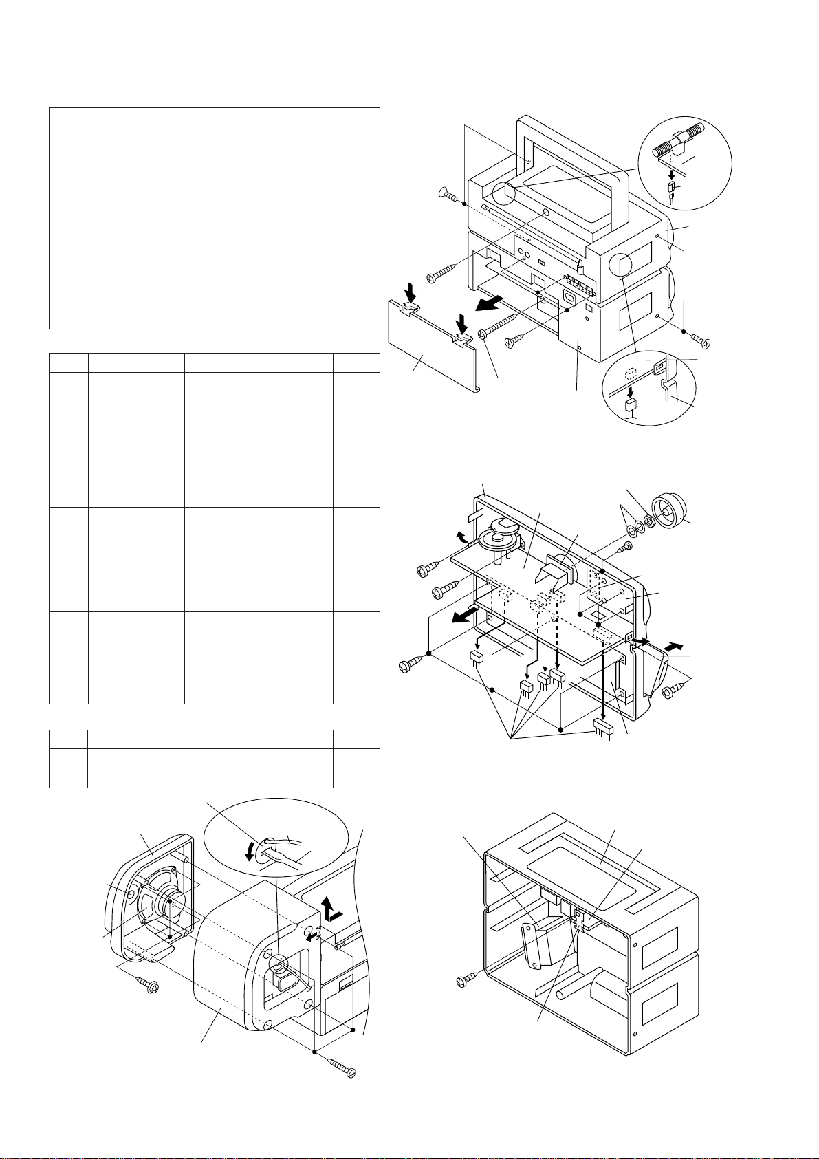
DISASSEMBLY
Caution on Disassembly
Follow the below-mentioned notes when disassembling the
unit and reassembling it, to keep it safe and ensure excellent
performance:
1. Take cassette tape out of the unit.
2. Be sure to remove the power supply plug from the wall
outlet before starting to disassemble the unit and remove
the batteries from the unit.
3. Take off nylon bands or wire holders where they need be
removed when disassembling the unit. After servicing the
unit, be sure to rearrange the leads where they were
before disassembling.
4. Take sufficient care on static electricity of integrated
circuits and other circuits when servicing.
MAIN UNIT
STEP REMOVAL PROCEDURE FIGURE
1 Front Cabinet/ 1. Battery Compartment
Rear Cabinet Lid ...................(A1)x1 4-1
2. Screw ................(A2)x4
3. Screw ................(A3)x1
4. Screw ................(A4)x1
5. Screw ................(A5)x3
6. Socket ...............(A6)x1
7. Tip .....................(A7)x1
2 Main PWB/ 1. Knob .................(B1)x1 4-2
Volume PWB 2. Socket ...............(B2)x5
3. Screw ................(B3)x1
4. Screw ................(B4)x1
3 Graphic Equalizer 1. Screw ................(C1)x4 4-2
PWB
4 LED PWB 1. Screw ................(D1)x2 4-2
5 Tape Mechanism 1. Open the cassette holder 4-2
2. Screw ................(E1)x5
6 Power PWB 1. Screw ................(F1)x1 4-3
2. Bracket..............(F2)x1
SPEAKER
STEP REMOVAL PROCEDURE FIGURE
1 Front Panel 1. Screw ................(G1)x4 4-4
2 Woofer 1. Screw ................(G2)x4 4-4
(A2) x2
ø3 x10mm
(A3) x1
ø3 x14mm
(A1) x1
(B4) x1
ø2 x4mm
(B3) x1
ø3 x8mm
(E1) x5
ø3x 8mm
(A4) x1
ø3 x28mm
Front Cabinet
(B2) x5
(A5) x3
ø3 x8mm
Figure 4-1
Main
PWB
Figure 4-2
Rear
Cabinet
Washer
Volume
PWB
(A6) x1
Nat
(D1)x2
ø3x8mm
LED PWB
Tape
Mechanism
Main
PWB
(A7) x1
Front
Cabinet
(A2) x2
ø3 x10mm
Main
PWB
Front
Cabinet
(B1) x1
Graphic
Equalizer
PWB
Open
Cassette
Holder
(Left/Right)
(C1) x4
ø3x8mm
Tweeter
Woofer
Speaker Cord
Holder
Front Panel
(G2) x4
ø3x 8mm
Speaker Box
Figure 4-4
Speaker
Cord
Driver
(G1) x4
ø3 x14mm
UNIT
– 4 –
Power
Transeformer
(F1) x1
ø3 x8mm
Rear Cabinet
Power PWB
(F2) x1
Figure 4-3
REMOVING AND REINSTALLING THE MAIN PARTS
TAPE MECHANISM SECTION
Perform steps 1, 2 and 5 of the disassembly method to remove
the tape mechanism. (See page 4.)
How to remove the record / playback, playback
and erase heads (See Fig. 5-1 and 5-2.)
1. Remove the screws (A1) x 2 pcs., to remove the record/
playback head.
2. Remove the hooks (A2) x 2 pcs., toward the center position
as shown in Fig. 5-1. and then extract the erase head upward.
3. Remove the screws (B1) x 2 pcs., to remove the playback
head.
Note:
After replacing the heads and performing the azimuth adjustment, be sure to apply screwlock.
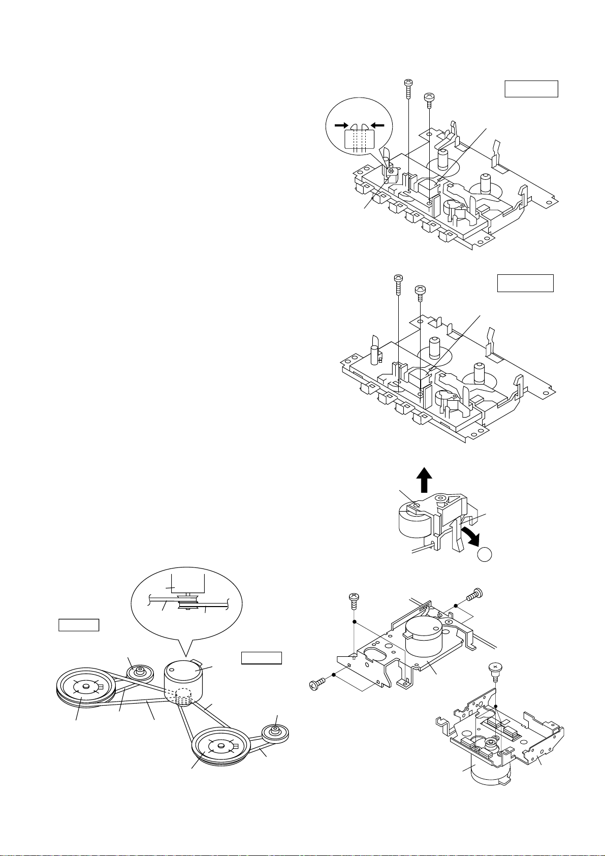
How to remove the pinch roller (See Fig. 5-3.)
1. Carefully bend the pinch roller pawl in the direction of the
arrow Â, and remove the pinch roller (C1) upwards.
How to remove the motor (See Fig. 5-4.)
1. Remove the belt.
2. Remove the screws (D1) x 6 pcs., to remove the motor
bracket.
3. Remove the screws (D2) x 3 pcs., to remove the motor.
Note:
When mounting the motor, pay attention to the motor mounting
angle.
Hook
(A2) x2
Erase
Head
(B1) x1
ø2x7mm
(A1) x1
ø2x7mm
(A1) x1
ø2x3mm
Figure 5-1
(B1) x1
ø2x3mm
WF-930Z
TAPE 1
Record/Playback
Head
TAPE 2
Playback
Head
How to remove the belts (See Fig. 5-5.)
1. Remove the main belt (E1) x 1 pc., at the tape 1 side from the
motor pulley.
2. Remove the main belt (E2) x 1 pc., at the tape 2 side from the
motor pulley.
3. Remove the REW/FF belt (E3) x 2 pcs., from the REW/FF
roller.
4. Put on the belts in the reverse order of removal.
Note:
When putting on the belt, ascertain that the belt is not twisted,
and clean it.
Moter
TAPE 2
Frywheel
REW / FF
Clutch Ass'y
REW / FF
Belt
(E3) x1
TAPE 2
Main Bert
Main
Belt
(E2) x1
TAPE 1
Main Bert
Moter
Main
Belt
(E1) x1
TAPE 1
REW / FF
Clutch Ass'y
(D1) x2
ø2 x4mm
Pinch Roller
(C1)
(D1) x2
ø2 x4mm
Figure 5-2
Figure 5-3
Motor
Bracket
Pinch Roller
Pawl
A
(D1) x2
ø2 x4mm
(D2) x3
Special Screw
Frywheel
Figure 5-5
REW / FF
Belt
(E3) x1
– 5 –
Motor
Figure 5-4
Motor
Bracket

WF-930Z
ADJUSTMENT
MECHANISM SECTION
• Driving Force Check
Torque Meter
Play: TW-2412 Tape 1: Over 50g
• Torque Check
Torque Meter
Play: TW-2111 30 to 60 g.cm 30 to 60 g.cm
Fast forward: TW-2231 55 to 120 g.cm 80 to 135 g.cm
Rewind: TW-2231 55 to 120 g.cm 80 to 135 g.cm
• Head Azimuth
Test Tape
MTT-114 Headphones Socket
• Tape Speed (Normal only)
Test Tape
MTT-111 Tape 1,2: VR501 3,000 ± 60 Hz Headphones
Adjusting
Point
Specified Value
Tape 2: Over 60 g
Specified Value
Tape 1 Tape 2
Instrument Connection
(Load resistance: 32 ohms)
Specified
Value
Instrument
Connection
socket(Load
resistance:
32 ohms)
TUNER SECTION
fL: Low-range frequency
fH: High-range frequency
• AM IF/RF
Specified
Test Stage
IF T3 Input: Antenna
MW Band fL: L6
Coverage fH: TC8
MW Tracking fL (600 kHz):
SW1 Band fL: L7
Coverage fH: TC4
SW1 Tracking fL (2.6 MHz):
SW2 Band fL: L8
Coverage fH: TC3
SW2 Tracking fL (8.5 MHz): L5
Value/Adjusting
Point
L3 (MW)
fH (1,400 kHz):
TC7
L4 (SW1)
fH (6.0 MHz):
TC2
fH (19 MHz): TC1
Instrument
Connection
Output: Pin 3 of IC2
TAPE SECTION
Position of each switch or control
Volume control Max
Beat cancel A
Function/Power Tape/Stand-by
Dubbing speed/Built-in Microphone OFF/Mic ON
• Bias Oscillation Frequency
Specified Value
Beat cancel A: 100 ± 4 kHz
• Playback Amplifier Sensitivity Check
Test Tape
MTT-118 1.3 V ± 3 dB Speaker terminal
Specified Value
B: 94 ± 4 kHz
C: 104 ± 4 kHz
Instrument Connection
(Load resistance: 3 ohms)
• FM IF/RF
Specified
Test Stage
IF T1
Detection T2
Band Coverage fL: L2
Tracking fL (88.0 MHz):
Value/Adjusting
Point
fH: TC6
L1
fH (108.0 MHz):
TC5
Instrument
Connection
Input: Antenna
Output: Pin 1 of IC1
• VCO Frequency
Specified ValueTest Stage
VR1 76 kHz ± 200 Hz Pin 13 of IC2
Instrument
Connection
– 6 –
 Loading...