

Sony WE475 - TC Dual Cassette Deck Service Manual
Model Name Using Similar Mechanism TC-WE435
DECK A TCM-230ASR41A
DECK B TCM-230ASR41B
US Model
Canadian Model
AEP Model
UK Model
E Model
Australian Model
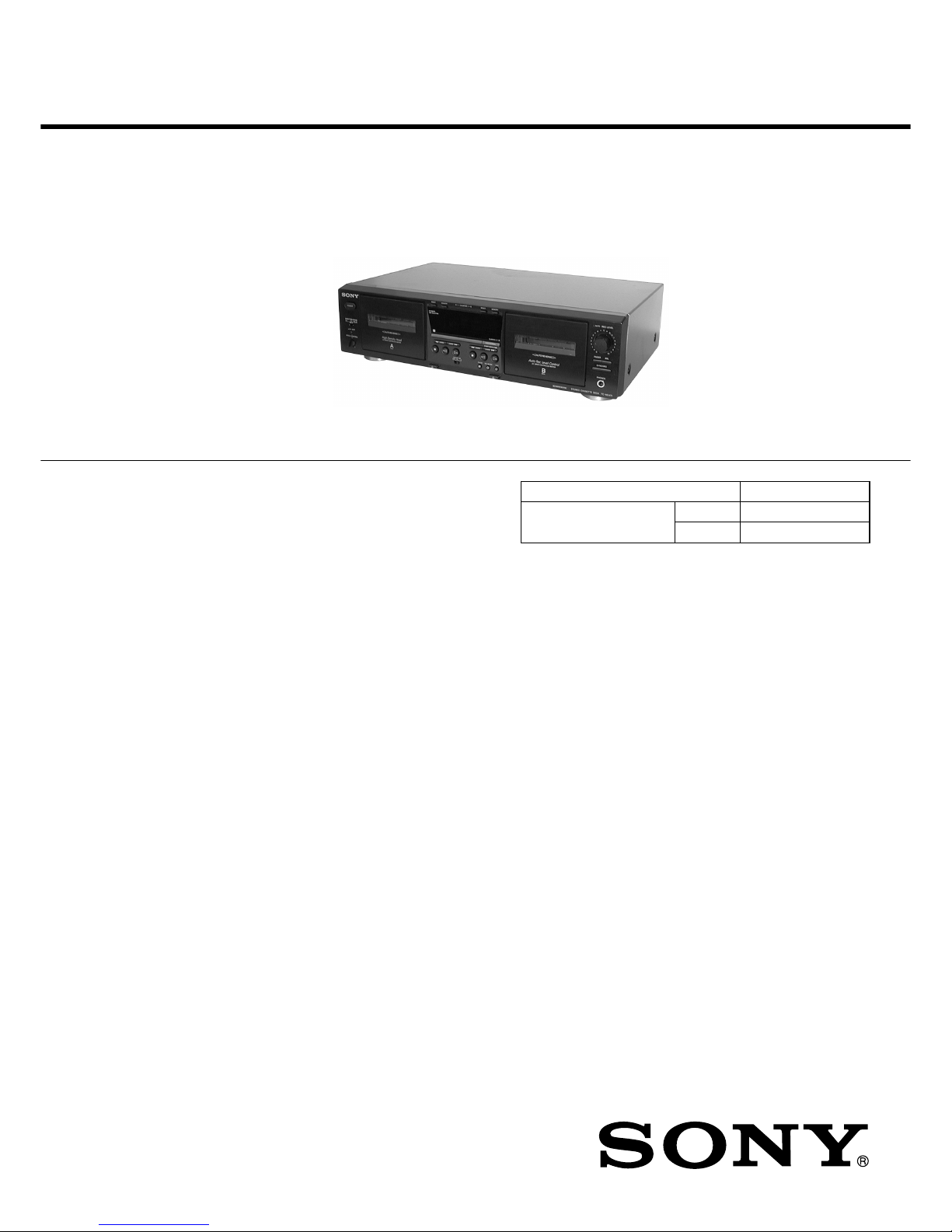
STEREO CASSETTE DECK
SPECIFICATIONS
Dolby noise reduction extension manufactured under license
from Dolby Laboratories Licensing Corporation.
HX Pro originated by Bang & Olufsen. “DOLBY”, the double-D
symbol ; and “HX PRO” are tr ademarks of Dolby Laboratories
Licensing Corporation.
TC-WE475
— Continued on next page —
Transport Mechanism Type
Ver 1.0 2001.04
Sony Corporation
Home Audio Company
Shinagawa Tec Service Manual Production Group
9-873-893-11
2001D0900-1
© 2001. 4
SERVICE MANUAL
System
Fast-winding time
Approx.100 sec. (with Sony C-60 cassette)
Signal-to-noise ratio (at peak level and weighted with Dolby
NR off)
55 dB, using Sony TYPE I cassette
57 dB, using Sony TYPE II cassette
58 dB, using Sony TYPE IV cassette
S/N ratio improvement
With Dolby B NR on:
Approx. 5 dB at 1 kHz, 10 dB at 5 kHz
With Dolby C NR on:
Approx. 15 dB at 500 Hz, 20 dB at 1 kHz
Harmonic distortion
0.4% (using Sony TYPE Icassette):
160 nWb/m 315 Hz, 3rd H.D.)
1.8% (using Sony TYPE IV cassette):
250 nWb/m 315 Hz, 3rd H.D.)
Frequency response (DOLBY NR OFF)
30-16,000 Hz (±3 dB, IEC), 20-17,000 Hz
(±6 dB), using Sony TYPE I cassette
30-17,000 Hz (±3 dB, IEC), 20-18,000 Hz
(±6 dB), using Sony TYPE II cassette
30-19,000 Hz (±3 dB, IEC), 20-20,000 Hz
(±6 dB), 30-13,000 Hz (±3 dB, –4dB recording),
using Sony TYPE IV cassette
Wow and flutter
±0.15% W. Peak (IEC)
0.1% W. RMS (NAB)
±0.2% W. Peak (DIN)
Variable pitch range
Approx. –30 to +30 %
Inputs
Line inputs (phono jacks)
sensitivity 0.16 V, input impedance 47 kilohms
Outputs
Line outputs (phono jacks)
rated output level 0.5 V at a load impedance of
47 kilohms, load impedance over 10 kilohms
Headphones (stereo phone jack)
output level 0.25 mW at a load impedance of
32 ohms
2
TC-WE475
SAFETY-RELATED COMPONENT WARNING!!
COMPONENTS IDENTIFIED BY MARK 0 OR DOTTED LINE
WITH MARK 0 ON THE SCHEMATIC DIAGRAMS AND IN THE
PARTS LIST ARE CRITICAL TO SAFE OPERATION. REPLACE THESE COMPONENTS WITH SONY PARTS WHOSE
P AR T NUMBERS APPEAR AS SHO WN IN THIS MANUAL OR
IN SUPPLEMENTS PUBLISHED BY SONY.
ATTENTION AU COMPOSANT AYANT RAPPORT
À LA SÉCURITÉ!!
LES COMPOSANTS IDENTIFIÉS P AR UNE MARQUE 0 SUR LES
DIAGRAMMES SCHÉMA TIQ UES ET LA LISTE DES PIÈCES SONT
CRITIQUES POUR LA SÉCURITÉ DE FONCTIONNEMENT. NE
REMPLACER CES COMPOSANTS QUE PAR DES PIÈCES SONY
DONT LES NUMÉROS SONT DONNÉS DANS CE MANUEL OU
DANS LES SUPPLÉMENTS PUBLIÉS PAR SONY.
SAFETY CHECK-OUT
After correcting the original service problem, perform the following safety checks before releasing the set to the customer:
Check the antenna terminals, metal trim, “metallized” knobs, screws,
and all other exposed metal parts for AC leaka ge. Check leakage as
described below.
LEAKAGE
The AC leakage from any exposed metal part to earth Ground and
from all exposed metal parts to any exposed metal part having a
return to chassis, must not exceed 0.5 mA (500 microampers). Leakage current can be measured by any one of three methods.
1. A commercial leakage tester, such as the Simpson 229 or RCA
WT-540A. Follow the manufacturers’ instructions to use these
instruments.
2. A battery-operated AC milliammeter. The Data Precision 245
digital multimeter is suitable for this job.
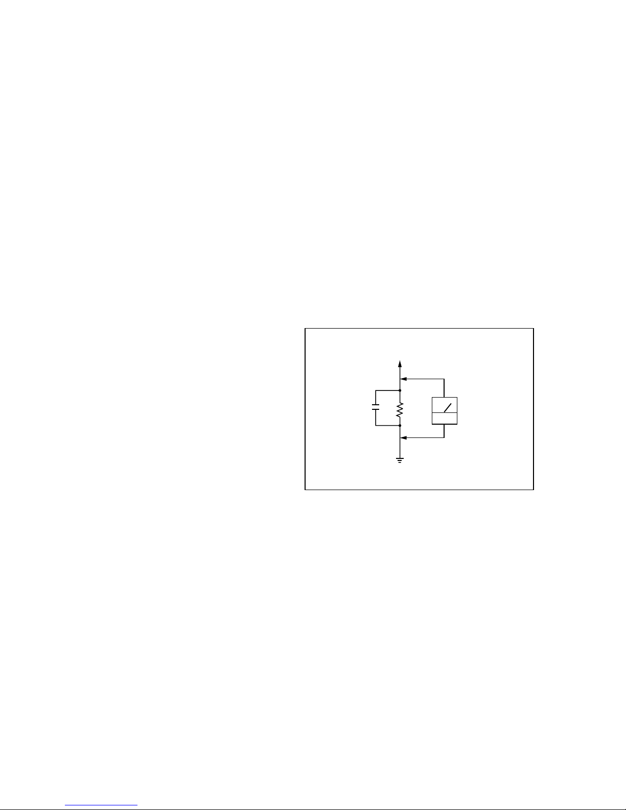
3. Measuring the voltage drop across a resistor by means of a V OM
or battery-operated A C v oltmeter. The “limit” indication is 0.75
V, so analog meters must have an accurate low-voltage scale.
The Simpson 250 and Sanwa SH-63Trd are examples of a passive VOM that is suitable. Nearly all battery operated digital
multimeters that have a 2V AC range are suitable. (See Fig. A)
Fig. A. Using an AC voltmeter to check AC leakage.
0.15µF
To Exposed Metal
Parts on Set
1.5kΩ
AC
voltmeter
(0.75V)
Earth Ground
General
Power requirements
U.S.A.and Canadian models:
120 V AC, 60Hz
European models:
230 V AC, 50/60Hz
Australian models:
240 V AC, 50/60Hz
Other models:
120/220/230-240 V AC, 50/60Hz
Adjustable with voltage selector
Power consumption
18 watts
Dimensions (w/h/d)
Approx. 430 × 120 × 300 mm
Mass 4.2 kg
Supplied accessories
Audio connecting cords (2)
Control A1II cable (1)*
*Supplied for Canadian models only
Design and specifications are subject to change
without notice.
3
TC-WE475
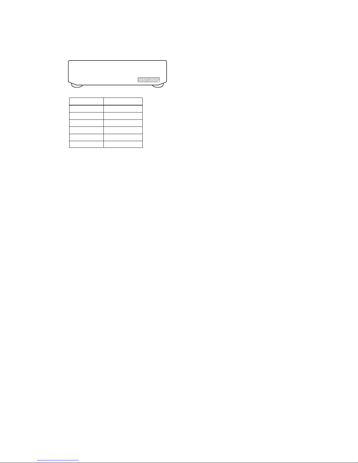
PA RTS No. MODEL
4-232-514-0s US model
4-232-514-1s CND model
4-232-514-2s AEP model
4-232-514-3s UK model
4-232-514-4s SP model
4-232-514-5s AUS model
MODEL IDENTIFICATION
–Back panel–
Part No.
• Abbreviation
CND : Canadian model
SP : Singapore model
AUS : Australian model
TABLE OF CONTENTS
1. GENERAL .......................................................................... 4
2. DISASSEMBLY
2-1. Case ......................................................................................5
2-2. Front Panel Assy ................................................................... 5
2-3. Cassette Lid Assy (Deck A/B) .............................................. 6
2-4. Mechanism Deck Assy (Deck A/B) ...................................... 6
3. SERVICE MODE .............................................................. 7
4. MECHANICAL ADJUSTMENTS................................. 8
5. ELECTRICAL ADJUSTMENTS ................................. 8
6. DIAGRAMS
6-1. Circuit Boards Location ...................................................... 12
6-2. Printed Wiring Board – MAIN Section –............................ 14
6-3. Schematic Diagram – MAIN (1/4) Section –...................... 15
6-4. Schematic Diagram – MAIN (2/4) Section –...................... 16
6-5. Schematic Diagram – MAIN (3/4) Section –...................... 17
6-6. Schematic Diagram – MAIN (4/4) Section –...................... 18
6-7. Printed Wiring Board – DECK A Section – ........................ 19
6-8. Schematic Diagram – DECK A Section –........................... 19
6-9. Printed Wiring Board – DECK B Section –........................ 19
6-10. Schematic Diagram – DECK B Section –......................... 19
6-11. Schematic Diagram – DISPLAY Section –....................... 20
6-12. Printed Wiring Board – DISPLAY Section – .................... 21
6-13. Schematic Diagram – PANEL Section –........................... 22
6-14. Printed Wiring Board – PANEL Section –........................ 23
6-15. Schematic Diagram – POWER Section – ......................... 24
6-16. Printed Wiring Board – POWER Section – ...................... 25
6-17. IC PIN FUNCTION .......................................................... 26
7. EXPLODED VIEWS
7-1. Case Section ........................................................................ 27
7-2. Chassis Section ................................................................... 28
7-3. Cassette Holder Section ...................................................... 29
7-4. Front Panel Section ............................................................. 30
7-5. Tape Mechanism Section .................................................... 31
8. ELECTRICAL PARTS LIST ........................................ 32
4
TC-WE475
SECTION 1
GENERAL
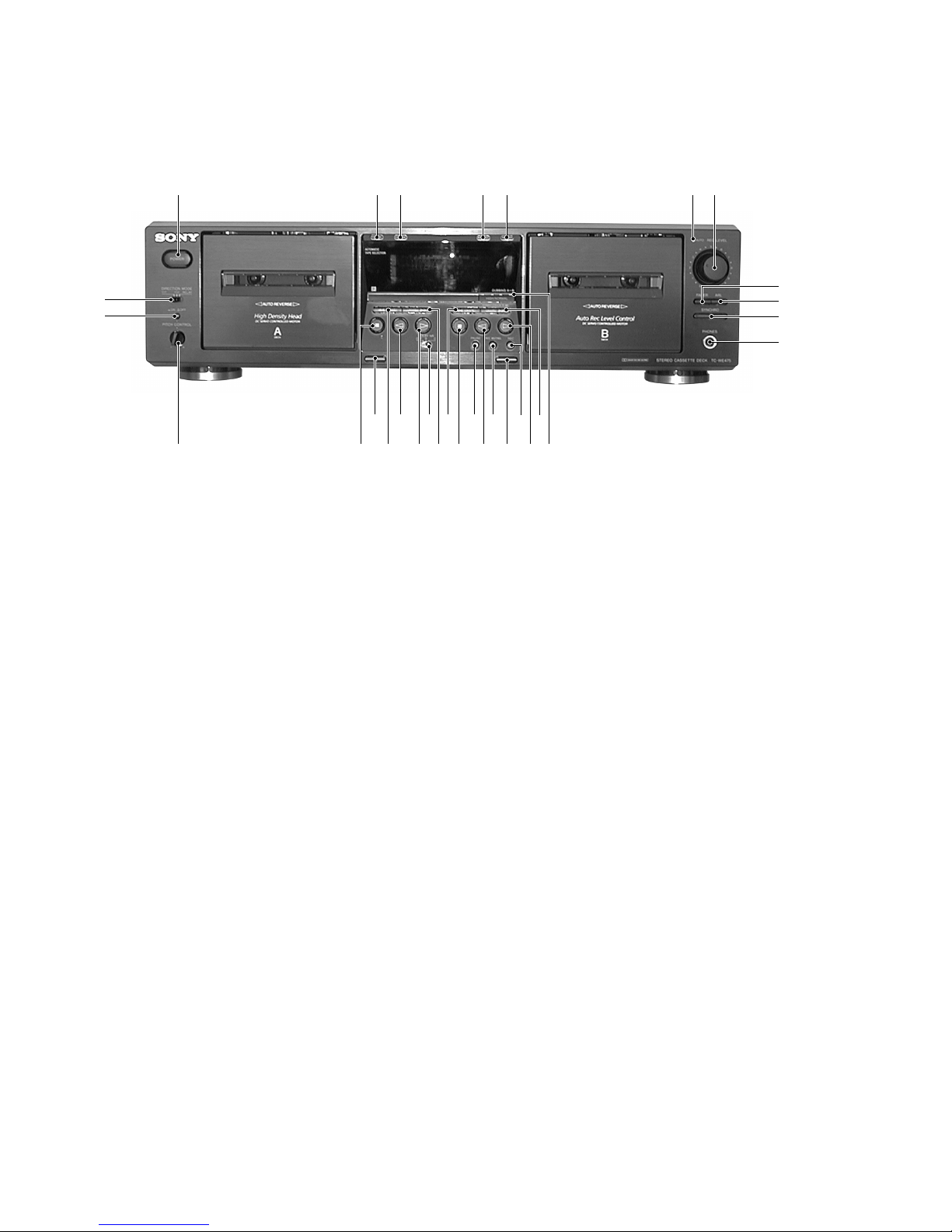
Front Panel
Location of Parts and Controls
1 POWER button
2 RESET (Deck A) button
3 MEMORY (Deck A) button
4 RESET (Deck B) button
5 MEMORY (Deck B) button
6 AUTO REC LEVEL indicator
7 REC LEVEL knob
8 FADER button
9 ARL button
q; SYNCHRO button
qa PHONES jack
qs HIGH/NOMAL button
qd (AMS) M (Deck B) button
qf H (Deck B) button
qg REC z button
qh A (Eject) (Deck B) button
qj REC MUTING W button
qk h (Deck B) button
ql PAUSE X button
w; x (Deck B) button
wa m (AMS) (Deck B) button
ws (AMS) M (Deck A) button
wd DOLBY NR OFF B/C switch
wf H (Deck A) button
wg h (Deck A) button
wh m (AMS) (Deck A) button
wj A (Eject) (Deck A) button
wk x (Deck A) button
wl PITCH CONTROL knob
e; PITCH CONTROL button
ea DIRECTION MODE switch
• AMS is the abbreviation for Automatic Music Sensor.
1 2 3 4 5 6 7
e;
ea
wj
wl
ql qjwg wd
wf w; qk qhwh
9
0
qa
8
ws qs
qd
qfwk
qg
wa
5
TC-WE475
SECTION 2
DISASSEMBLY
Note : Follow the disassembly procedure in the numerical order given.
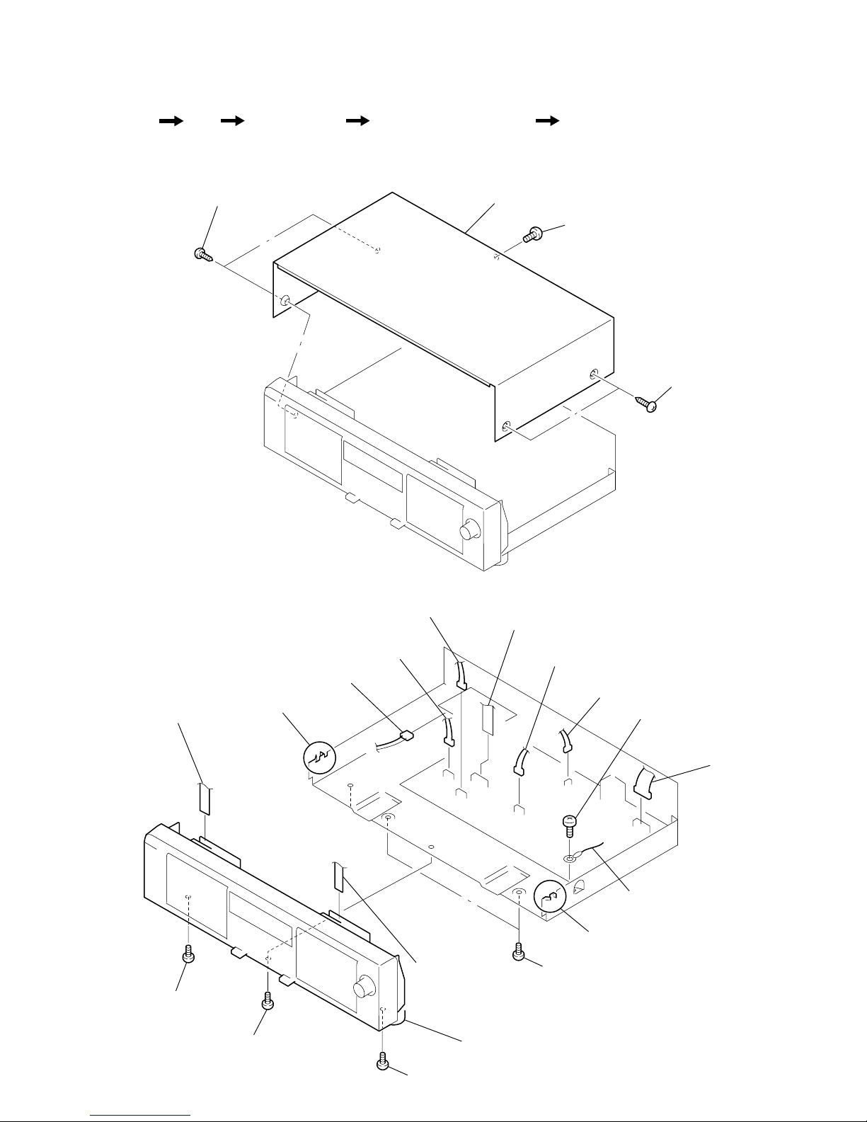
2-1. CASE
2-2. FRONT PANEL ASSY
1
screw
(BVTT 3x6)
2
two screws
(case 3 TP2)
3
two screws
(case 3 TP2)
4
case
qs
screw
(BVTP 3x8)
qf
screw
(BVTP 3x8)
qd
screw
(BVTP 3x8)
qg
two screws
(BVTT 3x6)
qj
claw
qh
claw
qk
front panel assy
8
CN301
7
CN401
2
CN807
1
CN5802
3
CN803
4
CNA806
5
flat type wire
(Deck A)
9
CN002
6
flat type wire
(Deck B)
0
screw
(BVTP 3x8)
qa
wire
Set Case
Front Panel Assy Cassette Lid Assy (Deck A/B) Mechanism Deck Assy (Deck A/B)
• The equipment can be removed using the following procedure.
6
TC-WE475
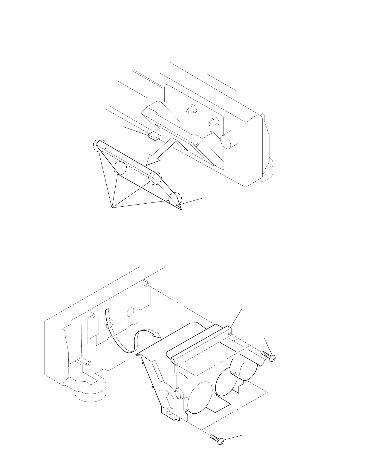
2-3. CASSETTE LID ASSY (DECK A/B)
2-4. MECHANISM DECK ASSY (DECK A/B)
2
four claws
1
Push the EJECT button.
3
cassette lid assy
1
two screws
(BVTP 2.6x8)
3
mechanism deck assy
2
two screws
(BVTP 2.6x8)
7
TC-WE475
RESET 0
MEMORY 1
m (AMS) 2
(AMS) M 3
x Grid check display (*1)
h 4
H 5
DIRECTION MODE switch
g h
s PLAY
RELAY H
A deck side
Button Display
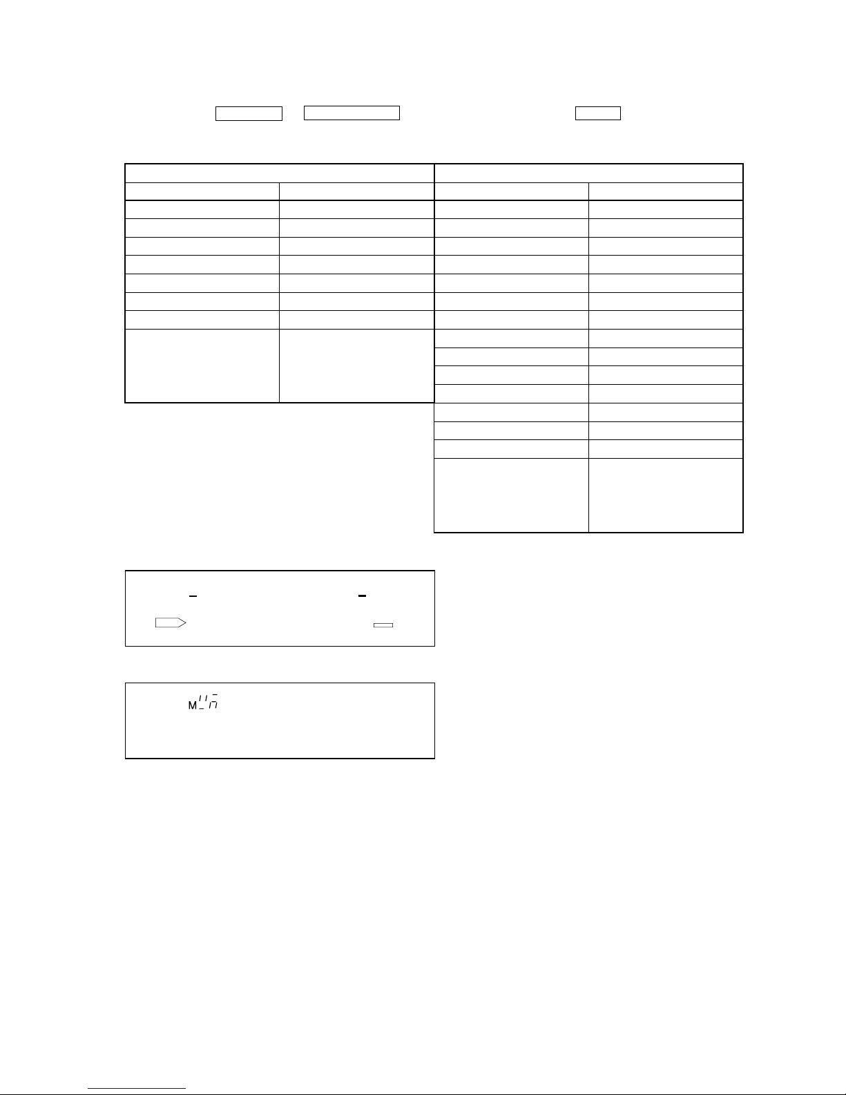
KEY CHECK & DISPLAY CHECK MODE
While pressing the h (A deck) and REC MUTING W buttons with the power off, press the POWER button to turn on the power.
The fluorescent indicator tube displays the number or special message corresponding to the button pressed.
The message displayed differs according to the position of the switch.
SECTION 3
SERVICE MODE
RESET 0
MEMORY 1
HIGH/NOMAL 2
m (AMS) 3
(AMS) M 4
x Segment check display (*2)
h 5
H 6
PAUSE X 7
REC MUTING W 8
REC z 9
FADER A
ARL b
SYNCHRO All lit
DOLBY NR switch
OFF h
B PLAY
C H
B deck side
Button Display
Grit check display (*1)
Segment check display (*2)
RMS
8
TC-WE475
PRECAUTION
1. Clean the following parts with a denatured alcohol-moistened
swab :
record/playback/erase head pinch roller
rubber belts capstan
idlers
2. Demagnetize the record/playback head with a head demagnetizer.
3. Do not use a magnetized screwdriver for the adjustment.
4. After the adjustments, apply suitable locking compound to the
parts adjusted.
5. The adjustments should be performed with the rated power supply voltage unless otherwise noted.
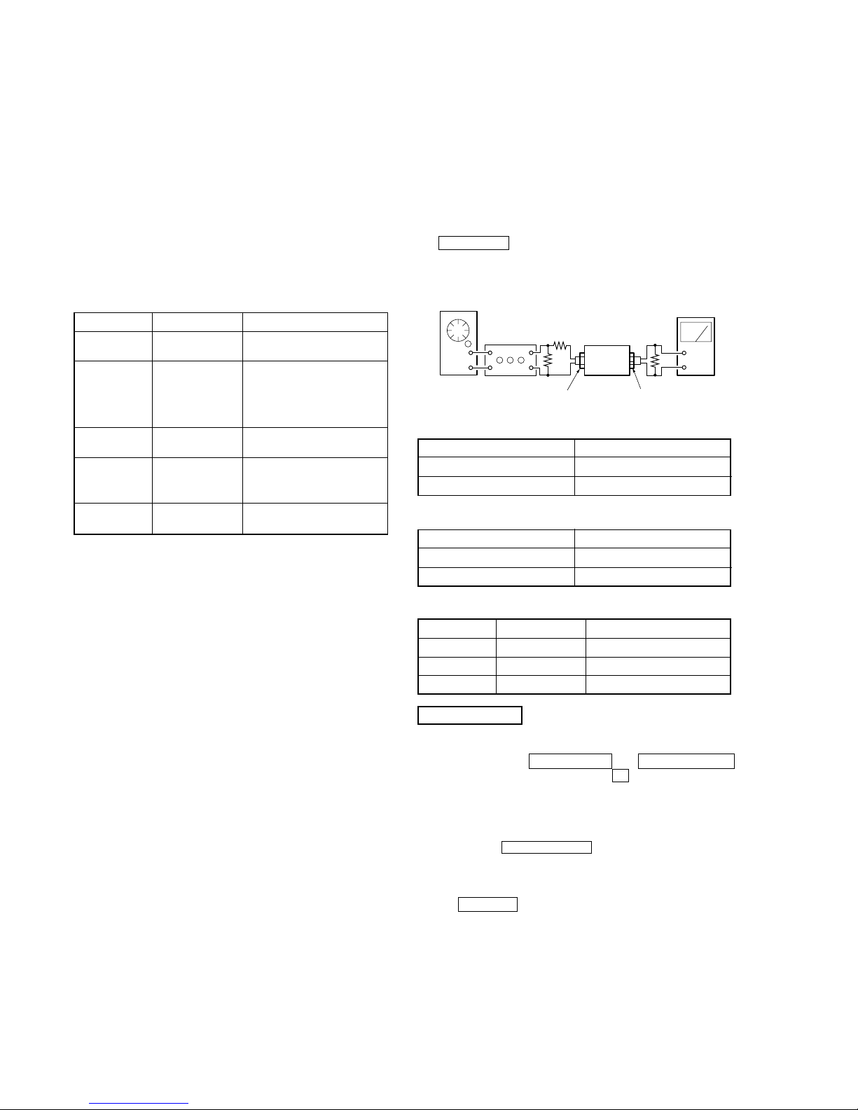
Torque Measurement
SECTION 5
ELECTRICAL ADJUSTMENTS
SECTION 4
MECHANICAL ADJUSTMENTS
PRECAUTION
1. The adjustment should be performed in the publication.
(Be sure to male playback adjustment at first.)
2. The adjustments and measurement should be performed for both
L-CH and R-CH.
• Switch position
DOLBY NR switch : OFF
DIRECTION MODE switch : g
• Standard record position :
Deliver the standard input signal le vel to input jack and set the
REC LEVEL knob to obtain the standard output signal level
as follows.
– Record Mode–
0 dBs = 0.775 V
Standard Input Level
Test Mode
1. While pressing the H (DECK A) and REC MUTING W
buttons with the power off, press the ! button to turn on the
power. The fluorescent displa y tube lights up for about one second, and the test mode is set. The test mode performs the following two special functions.
• Playback speed switching function
Pressing the HIGH/NORMAL button switches the playback
speed between standard/double speed.
• Counter RESET & MEMORY function
Resets the counter when recording starts. When rewound with
the m (AMS) button after recording, stops at the point where
recording started.
2. To release the test mode, turn OFF the power switch.
Mode Torque meter Meter reading
Forward
CQ-102C
30 to 65 g • cm
(0.42 to 0.90 oz • inch)
Forward
back
tension
CQ-102C
DECK A : 1 to 6 g • cm
(0.014 to 0.083 oz • inch)
DECK B : 2 to 9 g • cm
(0.028 to 0.125 oz • inch)
Reverse CQ-102RC
30 to 65 g • cm
(0.42 to 0.90 oz • inch)
Reverse
back
tension
CQ-102RC
1 to 6 g • cm
(0.014 to 0.083 oz • inch)
FF/REW
CQ-201B
70 to 120 g • cm
(0.97 to 1.67 oz • inch)
set
–
+
AF OSC
attenuator
10 kΩ
600 Ω
LINE IN
level mete
r
LINE OUT
47 kΩ
Standard Output Level
Test T ape
Input terminal LINE IN
source impedance 10 kΩ
input signal level 0.5 V (–3.8 dBs)
Tape Contents Use
P-4-A100 10 kHz, –10 dB Azimuth Adjustment
WS-48B 3 kHz, 0 dB Tape Speed Adjustment
P-4-L300 315 Hz, 0 dB PB Level Adjustment
Input terminal LINE IN
source impedance 10 kΩ
input signal level 0.5 V (–3.8 dBs)
9
TC-WE475
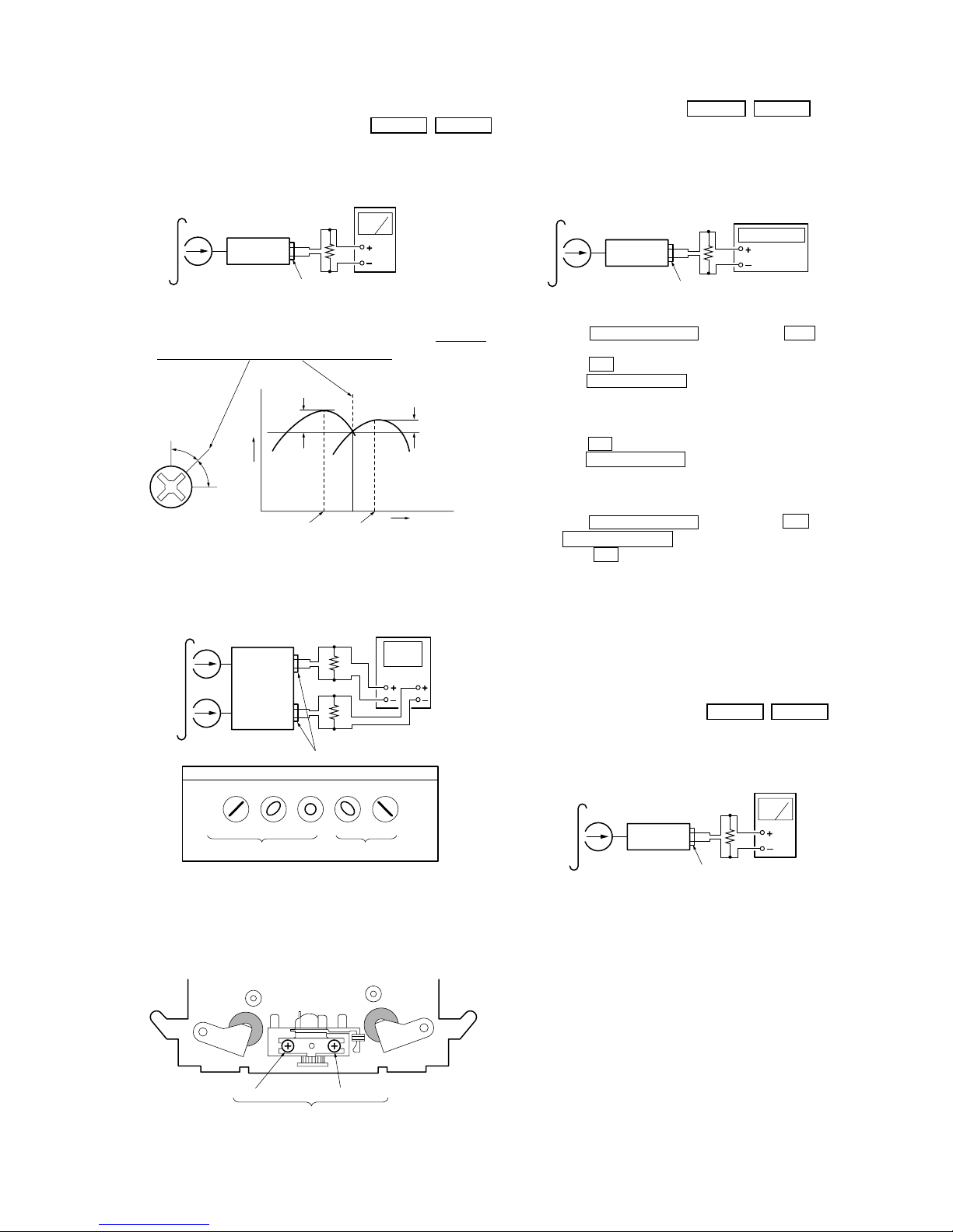
Record/Playback Head Azimuth Adjustment
DECK A DECK B
Procedure:
1. Forward Playback Mode
2. Turn the adjustment screw for the maximum output levels. If
these levels do not match, turn the adjustment screw until both
of output levels match together within 1 dB.
3. Playback Mode
4. Change the reverse playback mode and repeat the steps 1 to 3.
5. After the adjustment, lock the adjustment screws with suitable
locking compound.
Adjustment Location: – record/playback head –
Tape speed Adjustment DECK A DECK B
Adjust DECK A first
Procedure:
– Forward Playback Mode –
(High speed adjustment)
1. Press the PITCH CONTROL button to set to OFF .
2. Set to test mode. (Refer to page 11.)
3. Press the H button to playback.
4. Press the HIGH/NORMAL button to playback at double speed.
5. Adjust RV316 (DECK A), RV416 (DECK B) so that the frequency counter reading becomes 5,980 ± 180 Hz.
(Normal speed adjustment)
6. Press the H button to playback.
7. Press the HIGH/NORMAL button to playback at normal speed.
8. Adjust RV317 (DECK A), RV417 (DECK B) so that the frequency counter reading becomes 3,000 ± 90 Hz.
(Pitch control adjustment) (DECK A)
9. Press the PITCH CONTROL button to set to ON .
10. Set PITCH CONTROL knob to mechanical center.
11. Press the H button to playback.
12. Adjust RV318 so that the frequency counter reading becomes
2,990 ± 90 Hz.
Adjustment Location: MAIN board (See page 14.)
Sample value of wow and flutter
W.RMS (JIS) less than 0.3% .
(test tape : WS-48B)
Playback Level Adjustment DECK A DECK B
Procedure:
– Forward Playback Mode –
Adjust DECK A : RV111 (L-CH), RV211 (R-CH) and
DECK B : RV121 (L-CH), RV221 (R-CH) so the level meter reading becomes the adjustment limits below.
Adjustment V alue:
LINE OUT level : –7.7 dBs ± 0.5 dB (0.301 to 0.338 V)
Level difference between channels : within 0.5 dB
Confirm that the LINE OUT level does not change in playback mode
while changing the mode from playback to stop several times.
Adjustment Location: MAIN board (See page 14.)
set
test tape
P-4-A100
(10 kHz, –10 dB)
level mete
r
LINE OUT
47 kΩ
within
1 dB
within
1 dB
output
level
R-CH
peak
R-CH
peak
L-CH
peak
L-CH
peak
screw
position
screw position
VH
Screen Pattern
set
In phase 45˚ 90˚ 135˚ 180˚
good wrong
47 kΩ
47 kΩ
L-CH
R-CH
test tape
P-4-A100
(10 kHz, –10 dB)
LINE OUT
oscilloscope
forward sidereverse side
adjustment screws
set
frequency counter
47 kΩ
LINE OUT
test tape
WS-48B
(3 kHz, 0 dB)
set
test tape
P-4-L300
(315 Hz, 0 dB)
level mete
r
LINE OUT
47 kΩ
10
TC-WE475
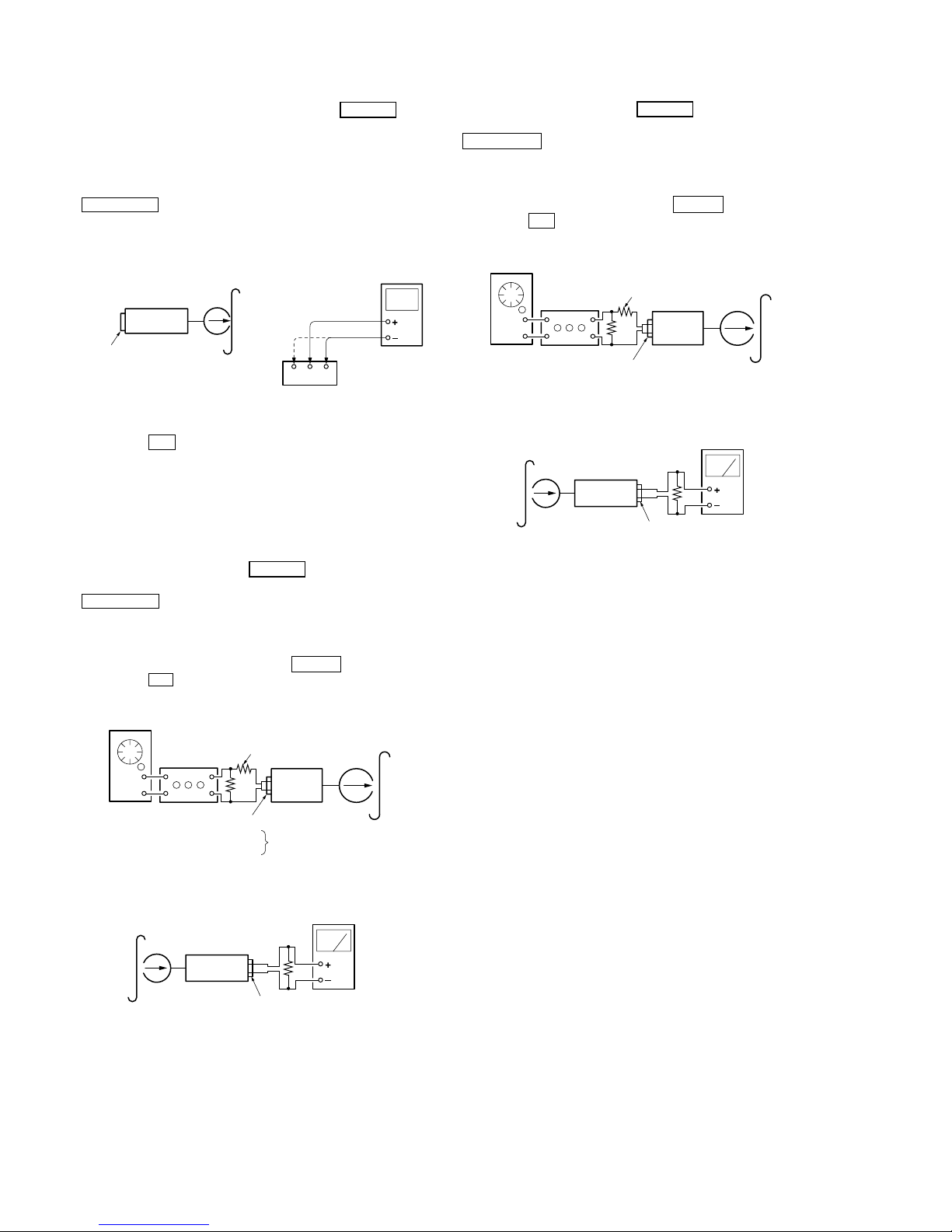
Bias Consumption Current Adjustment DECK B
This adjustment should be performed when replacing the head assy
or the bias oscillator transformer (T141, T241).
Setting:
REC LEVEL knob : standard recording position (See page 11.)
Procedure:
1. Connect the digital voltmeter to test point TP441.
2. Set RV141 (L-CH), RV241 (R-CH) to mechanical center.
3. Press the H button to playback.
4. Adjust T141 (L-CH), T241 (R-CH) so that the digital voltmeter
reading becomes minimum.
Adjustment V alue: Maximum 220 mV
Adjustment Location: MAIN board (See page 14.)
Record Bias Adjustment DECK B
Setting:
REC LEVEL knob : standard record position (See page 11.)
Procedure:
1. Set to test mode (See page 11.)
2. Insert a tape into deck B, press the REC z button and then
press the H button to start recording.
3. Record Mode
Record Level Adjustment DECK B
Setting:
REC LEVEL knob : standard record position (See page 11.)
Procedure:
1. Set to test mode (See page 11.)
2. Insert a tspe into deck B, press the REC z button and then
press the H button to start recording.
3. Record Mode
4. Playback Mode
set
321
blank tape
CS-413
TP441
L-CHR-CH
digital
voltmeter
LINE IN
no signal
set
AF OSC
attenuator
10 kΩ
600 Ω
LINE IN
1) 315 Hz
2) 10 kHz
50 mV (–23.8 dBs)
blank tap
e
CS-123
4. Playback Mode
set
recorded
portion
level mete
r
LINE OUT
47 kΩ
5. Confirm playback the signal recorded in step 2 become adjustment level as follows.
If the selevels do not adjustment lev el, adjust the R V141 (L-CH)
and RV241 (R-CH) to repeat steps 3 and 4.
Adjustment level:
The palyback output of 10 kHz level difference a gainst 315 Hz reference should be ± 0.5 dB.
Adjustment Location: MAIN board (See page 14.)
set
AF OSC
attenuator
10 kΩ
600 Ω
LINE IN
blank tap
e
CS-123
315 Hz, 50 mV (–23.8 dBs)
set
recorded
portion
level mete
r
LINE OUT
47 kΩ
5. Confirm playback the signal recorded in step 2 become adjustment level as follows.
If the selevels do not adjustment lev el, adjust the R V101 (L-CH)
and RV201 (R-CH) to repeat steps 3 and 4.
Adjustment V alue:
LINE OUT level : –23.8 dBs ± 0.5 dB (47.2 to 53.0 mV)
Adjustment Location: MAIN board (See page 14.)
11
TC-WE475
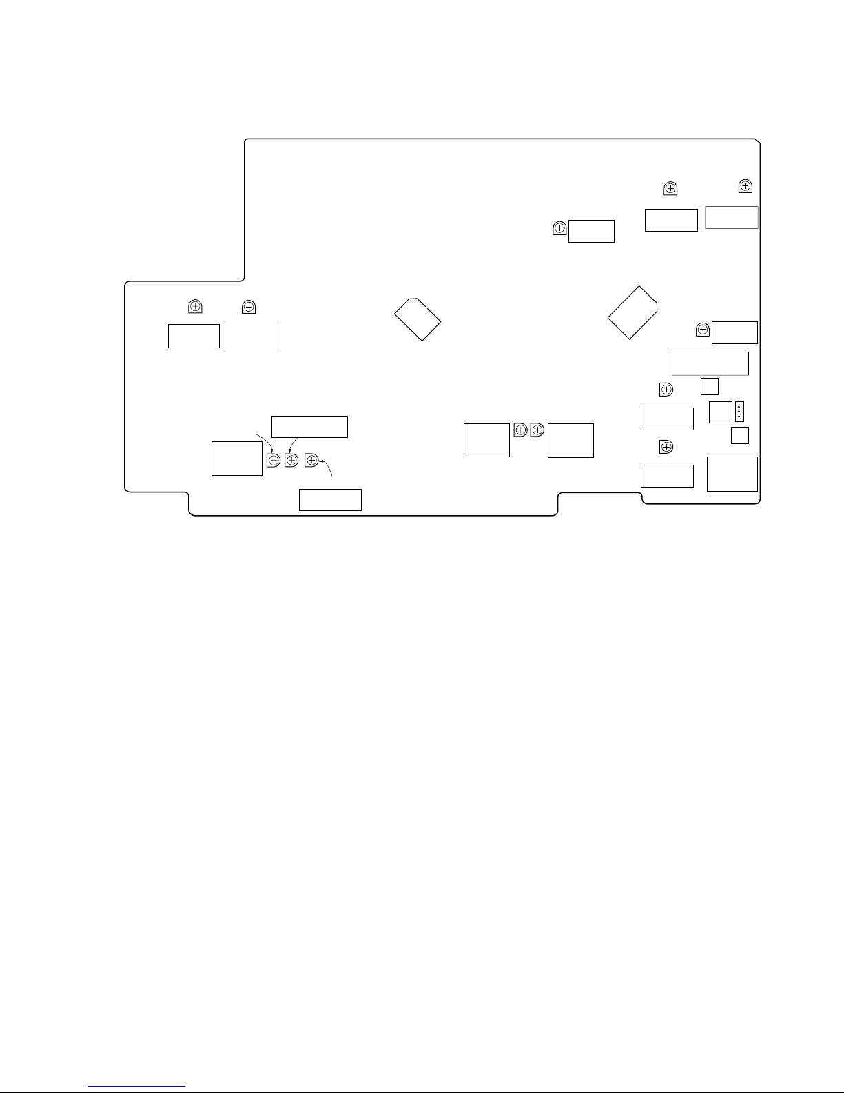
Adjustment Location: main board
RV111
PB LEVEL
DECK A (L)
RV211
PB LEVEL
DECK A (R)
RV318
PITCH
CONTROL
(DECK A)
RV317
NORMAL SPEED
(DECK A)
RV316
HIGH SPEED
(DECK A)
100
81
80
51
31
1
IC801
50
30
RV417
NORMAL
SPEED
(DECK B)
RV416
HIGH
SPEED
(DECK B)
RV241
REC BIAS
DECK B (R)
RV141
REC BIAS
DECK B (L)
RV201
REC
LEVEL (R)
REC
BIAS
T241
BIAS
CURRENT
DECK B (R)
BIAS CURRENT
DECK B (L)
T141
52
33
32
20
64
1
IC551
19
51
RV101
REC
LEVEL (L)
RV121
PB LEVEL
DECK B (L)
RV221
PB LEVEL
DECK B (R)
TP441
[MAIN board] (Component side)
12
TC-WE475
SECTION 6
DIAGRAMS
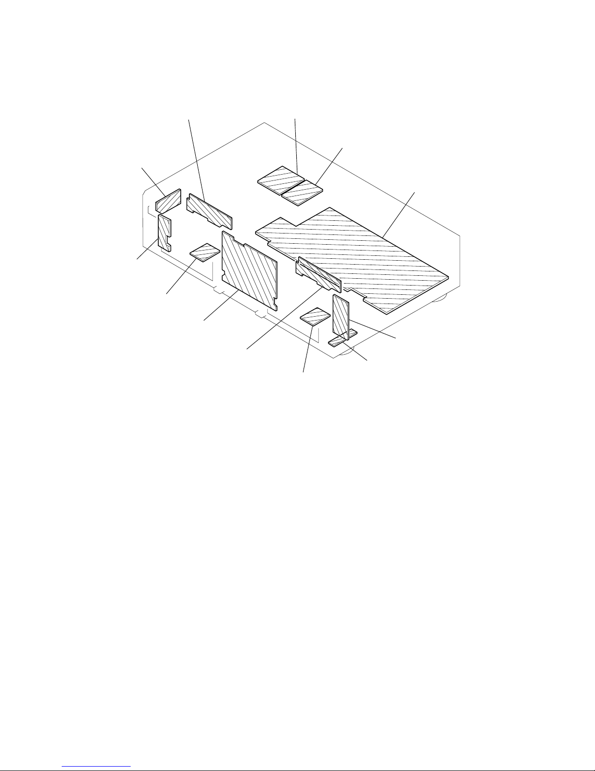
6-1. CIRCUIT BOARDS LOCATION
TRANS (A) board (v E)
(Except SP)
MAIN board
RECVOL board (
v
G
)
H.P board (v D)
HEAD RELAY(REC/PB) board
(Deck B)
HEAD RELAY(PB) board
(Deck A)
LEAF SW (REC/PB) board
(Deck B)
PANEL board (
v
A)
DIRECTION board (
v
C)
POWER board (
v
F)
LEAF SW (REC/PB) board
(Deck A)
TRANS (B) board (v B)
• vA to vG are including into the mounted PANEL board.
 Loading...