

Sony WD-850 Operating Instructions Manual

UHF
4-116-913-11 (1)
Antenna Divider
Operating Instructions _____ GB
Mode d'emploi____________ FR
Bedienungsanleitung ______ DE
Istruzioni per l’uso_________ IT
Manual de instrucciones ___ ES
WD-850
© 2008 Sony Corporation
English
Important Safety Instructions
• Read these instructions.
• Keep these instructions.
• Heed all warnings.
• Follow all instructions.
• Do not use this apparatus near water.
• Clean only with dry cloth.
• Do not block any ventilation openings. Install in
accordance with the manufacturer's instructions.
• Do not install near any heat sources such as radiators,
heat registers, stoves, or other apparatus (including
amplifiers) that produce heat.
• Do not defeat the safety purpose of the polarized or
grounding-type plug. A polarized plug has two blades
with one wider than the other. A grounding type plug
has two blades and a third grounding prong. The wide
blade or the third prong are provided for your safety. If
the provided plug does not fit into your outlet, consult an
electrician for replacement of the obsolete outlet.
• Protect the power cord from being walked on or pinched
particularly at plugs, convenience receptacles, and the
point where they exit from the apparatus.
• Only use attachments/accessories specified by the
manufacturer.
• Use only with the cart, stand, tripod, bracket,
or table specified by the manufacturer, or sold
with the apparatus. When a cart is used, use
caution when moving the cart/apparatus
combination to avoid injury from tip-over.
• Unplug this apparatus during lightning storms or when
unused for long periods of time.
• Refer all servicing to qualified service personnel.
Servicing is required when the apparatus has been
damaged in any way, such as power-supply cord or plug
is damaged, liquid has been spilled or objects have fallen
into the apparatus, the apparatus has been exposed to
rain or moisture, does not operate normally, or has been
dropped.
This symbol is intended to alert the user to
the presence of uninsulated “dangerous
voltage” within the product’s enclosure
that may be of sufficient magnitude to
constitute a risk of electric shock to
persons.
This symbol is intended to alert the user to
the presence of important operating and
maintenance (servicing) instructions in
the literature accompanying the
appliance.
CAUTION
The apparatus shall not be exposed to dripping or
splashing. No objects filled with liquids, such as vases,
shall be placed on the apparatus.
WARNING
To reduce the risk of fire or electric shock,
do not expose this apparatus to rain or
moisture.
To avoid electrical shock, do not open the
cabinet. Refer servicing to qualified
personnel only.
THIS APPARATUS MUST BE EARTHED.
2
For the customers in Europe
Hereby, Sony Corporation, declares that this WD-850 is in
compliance with the essential requirements and other
relevant provisions of the Directive 1999/5/EC.
For details, please access the following URL:
http://www.compliance.sony.de/
Voor de klanten in Europa
Hierbij verklaart Sony Corporation dat het toestel WD-850
in overeenstemming is met de essentiële eisen en de andere
relevante bepalingen van richtlijn 1999/5/EG.
Nadere informatie kunt u vinden op:
http://www.compliance.sony.de/
For kunder i Europa
Härmed intygar Sony Corporation att denna WD-850 står
I överensstämmelse med de väsentliga egenskapskrav och
övriga relevanta bestämmelser som framgår av direktiv
1999/5/EG.
För ytterligare information gå in på följande hemsida:
http://www.compliance.sony.de/
Para os clientes da Europa
Sony Corporation declara que este WD-850 está conforme
com os requisitos essenciais e outras disposições da
Directiva 1999/5/CE.
Para mais informacoes, por favor consulte a seguinte URL:
http://www.compliance.sony.de/
For kunder i Europa
Undertegnede Sony Corporation erklærer herved, at
følgende udstyr WD-850 overholder de væsentlige krav og
øvrige relevante krav i direktiv 1999/5/EF.
For yderligere information gå ind på følgende
hjemmeside:
http://www.compliance.sony.de/
Pro zákazníky v Evropě
Sony Corporation tímto prohlašuje, že tento WD-850
je ve shodě se základními požadavky a dalšími
příslušnými ustanoveními směrnice 1999/5/ES.
Podrobnosti lze získat na následující URL:
http://www.compliance.sony.de/
Euroopa klientidele
Sony Corporation kinnitab käesolevaga seadme WD-850
vastavust 1999/5/EÜ direktiivi põhinõuetele ja nimetatud
direktiivist tulenevatele teistele asjakohastele sätetele.
Üksikasjalikum info:
http://www.compliance.sony.de/.
Euroopassa oleville asiakkaille
Sony Corporation vakuuttaa täten että WD-850 tyyppinen
laite on direktiivin 1999/5/EY oleellisten vaatimusten ja
sitä koskevien direktiivin muiden ehtojen mukainen.
Halutessasi lisätietoja, käy osoitteessa:
http://www.compliance.sony.de/
For kundene i Europa
Sony Corporation erklærer herved at utstyret WD-850 er i
samsvar med de grunnleggende krav og øvrige relevante
krav i direktiv 1999/5/EF.
For flere detaljer, vennligst se:
http://www.compliance.sony.de/
Για τους πελάτες στην Eυρώπη
Με την παρούσα η Sony Corporation δηλώνει τι
WD-850 συμμορφώνεται προς της ουσιώδεις
απαιτήσεις και τις λοιπές σχετικές διατάξεις της
οδηγίας 1999/5/ΕΚ.
Για λεπτομέρειες παρακαλούμε πως ελένξετε
την ακλουθη σελίδα του διαδικτύου:
http://www.compliance.sony.de/
Európai vásárlóink fi gyelmébe
Alulírott, Sony Corporation nyilatkozom, hogy a(z)
WD-850 megfelel a vonatkozó alapvető
követelményeknek és az 1999/5/EC irányelv egyéb
előírásainak.
További információkat a következő weboldalon
találhat:
http://www.compliance.sony.de/
GB
Dotyczy klientów z Europy
Niniejszym Sony Corporation oświadcza, że WD-850
jest zgodne z zasadniczymi wymaganiami oraz innymi
stosownymi postanowieniami Dyrektywy 1999/5/WE.
3

Szczegółowe informacje znaleźć można pod
następującym adresem URL:
http://www.compliance.sony.de/
Pentru clienţii din Europa
Prin prezenta, Sony Corporation declară că acest WD850 respectă cerinţele esenţiale și este în conformitate
cu prevederile Directivei 1995/5/EC.
Pentru detalii, vă rugăm accesaţi următoarea adresă:
http://www.compliance.sony.de/
Pre zákazníkov v Európe
Sony Corporation týmto vyhlasuje, že WD-850 spĺňa
základné požiadavky a všetky príslušné ustanovenia
Smernice 1999/5/ES.
Podrobnosti získate na nasledovnej webovej adrese:
http://www.compliance.sony.de/
Za stranke v Evropi
Sony Corporation izjavlja, da je ta WD-850 v skladu z
bistvenimi zahtevami in ostalimi relevantnimi določili
direktive 1999/5/ES.
Za podrobnosti vas naprošamo, če pogledate naURL:
http://www.compliance.sony.de/
4

Table of Contents
Overview...........................................................................................6
Important notes on operation.........................................................6
Location and function of parts .......................................................7
Connection .......................................................................................9
Rack-mounting the unit.................................................................11
Specifications ................................................................................12
About the use of coaxial cable .............................................................. 6
Operating conditions ............................................................................. 6
Front panel............................................................................................. 7
Rear panel.............................................................................................. 8
Example 1: When two MB-X6 or MB-806A units are connected ........ 9
Example 2: When eight MB-8N units are connected (two directly and
six through cascade connections)............................................... 10
5

Overview
The WD-850 is a UHF antenna divider for use with a Sony
UHF wireless microphone system.
Antenna signal output to up to four
receivers
This unit is equipped with a 2-channel divider circuit that
allows it to send the antenna signals received by two AN820A UHF antennas to up to four receivers. This makes it
possible to easily configure a multi-channel diversity
receiving system by connecting Sony MB-X6/8N tuner
base units or similar equipment.
Cascade output connectors allowing
simultaneous use of up to two WD-850
channel dividers
Connection of the unit’s cascade connectors to two WD850 channel dividers enables signal output to a maximum
of eight tuner base units.
2-channel antenna input connectors
This unit provides two connectors for each channel.
Increasing the number of antennas to four makes it
possible to extend the range of wireless microphone use.
Important notes on
operation
About the use of coaxial cable
5D-2V or a higher grade coaxial cable (50 ohms) is
recommended for connecting the antennas to the tuner or
antenna divider. Use of 5C-2V or higher grade (75 ohms)
is also possible.
Signal loss: 5D-2V 50 m (164 ft.): 12.5 dB
100 m (328 ft.): 25 dB
5C-2V 50 m (164 ft.): 13.5 dB
100 m (328 ft.): 27 dB
Since signal loss in coaxial cable is affected more by the
length of the cable than the difference between 50 ohms
and 75 ohms, the cable should be as short as possible.
Operating conditions
Operate within a temperature range of 0C° to +50C°
(+32F° to +122F°).
Power supplied to the AN-820A UHF
antenna
Power is supplied to the AN-820A UHF antenna’s booster
amplifier. Interference or distortion can be easily
eliminated by turning off the power to the booster
amplifier.
1U-size EIA rack mount
The unit can be mounted in an EIA standard 19-inch rack
(1U size).
6
Overview / Important notes on operation
Location and function of parts
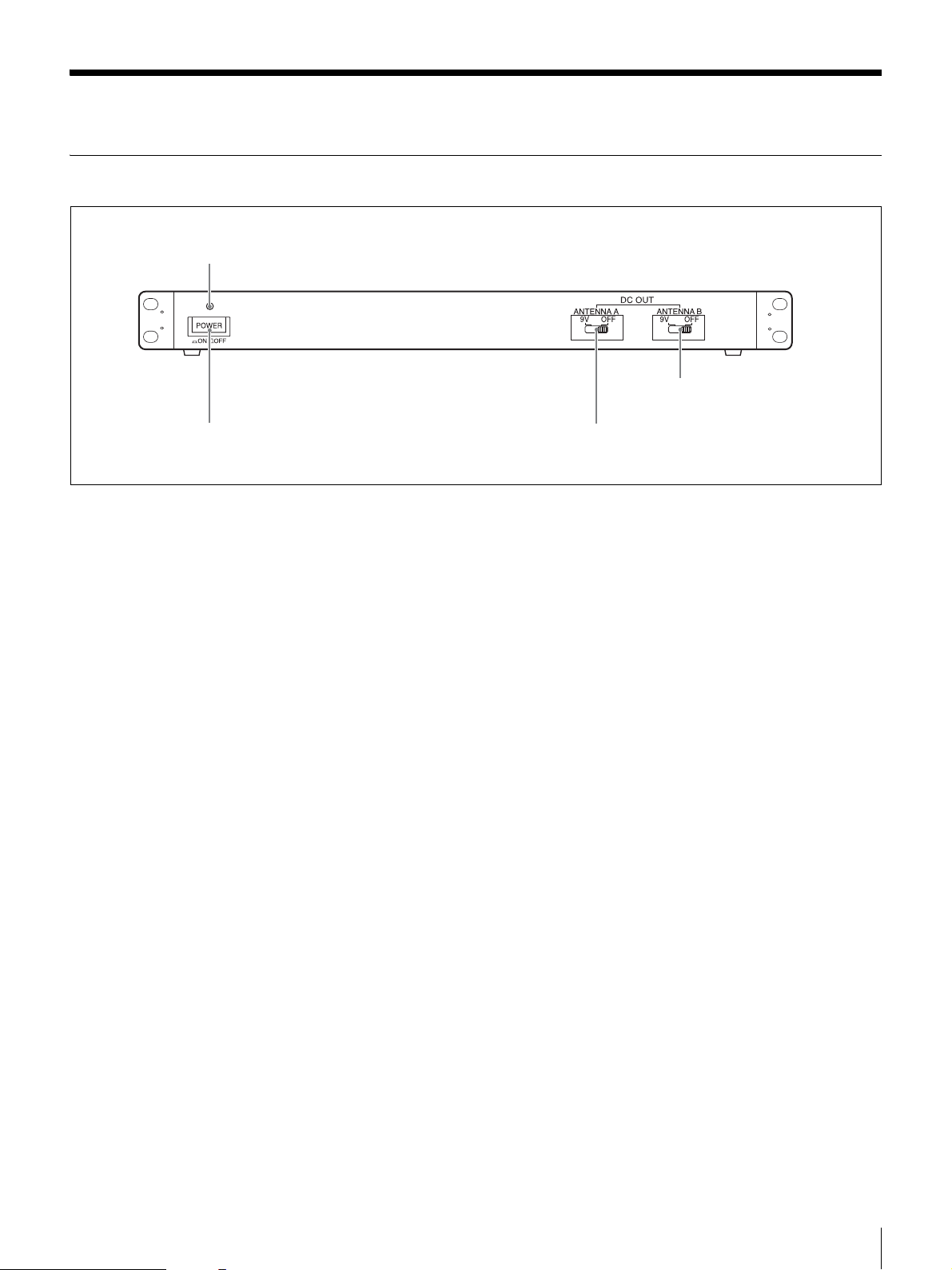
Front panel
1 POWER indicator
d ANTENNA B DC OUT
switch
2 POWER switch
a POWER indicator
Lights when the unit is turned on.
b POWER switch
Press to turn the unit on/off.
c ANTENNA A DC OUT (power supply to antenna
A) switch
Supplies 9V DC to the AN-820A UHF antenna connected
to the ANTENA A DC OUT 1 and 2 connectors. If
interference or distortion occurs, set to OFF.
d ANTENNA B DC OUT (power supply to antenna
B) switch
Supplies 9V DC to the AN-820A UHF antenna connected
to the ANTENA B DC OUT 1 and 2 connectors. If
interference or distortion occurs, set to OFF.
3 ANTENNA A DC OUT switch
Location and function of parts
7
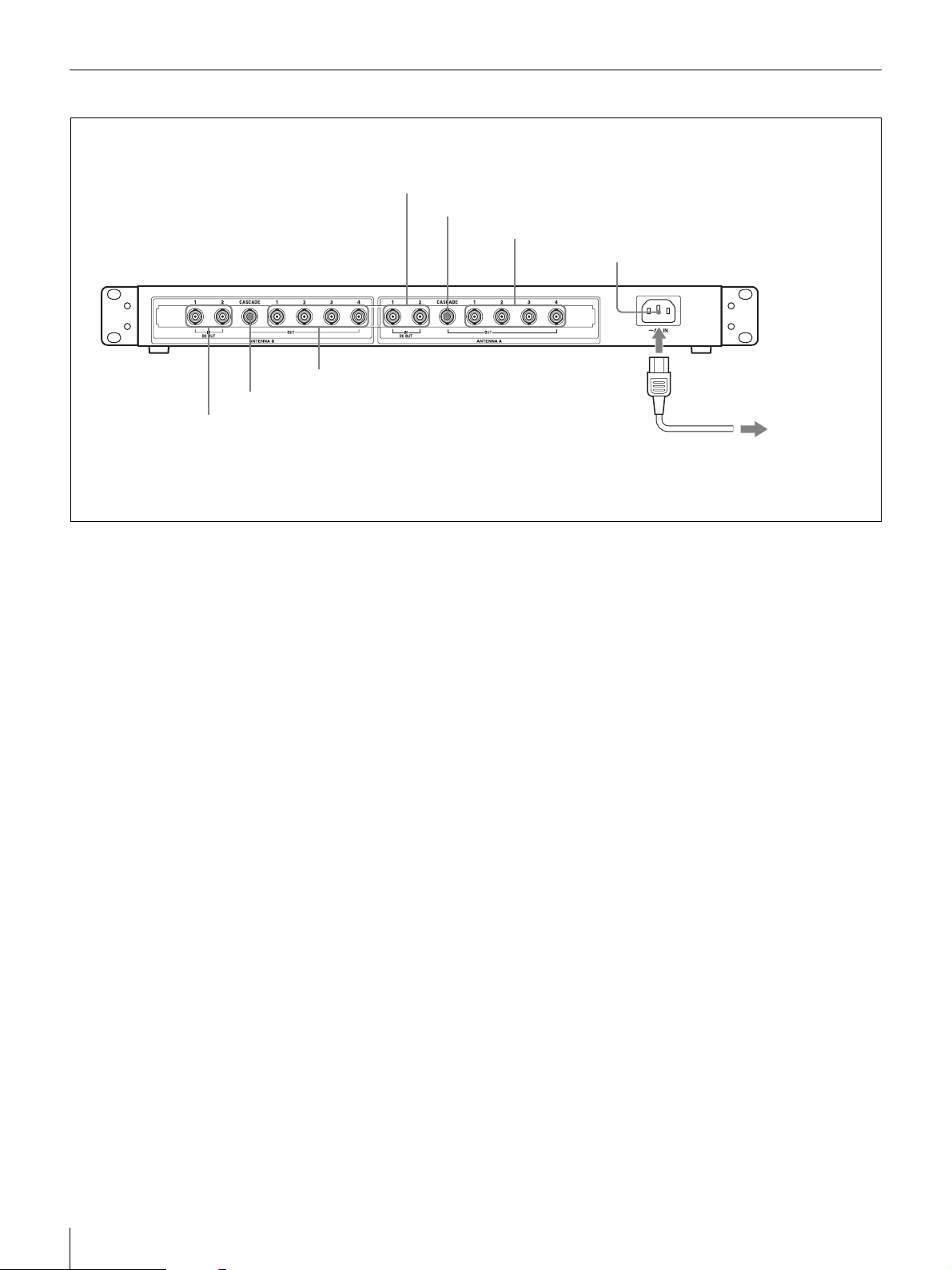
Rear panel
1 ANTENNA A IN/ DC OUT 1 and 2 connectors
2 ANTENNA A CASCADE connector
3 ANTENNA A OUT 1 to 4 connectors
4 AC IN connector
7 ANTENNA B OUT 1 to 4 connectors
6 ANTENNA B CASCADE connector
5 ANTENNA B IN/ DC OUT 1 and 2 connectors
ANTENNA A block
a ANTENNA A IN / DC OUT 1 and 2 (antenna A
input/DC power output 1 and 2) connectors
When connected by coaxial cable, the signal is input from
the AN-820A UHF antenna while power is supplied to the
antenna’s booster amplifier. The power supply can be set
to 9V or OFF using the ANTENNA A DC OUT switch on
the front panel. Depending on the required range of the
wireless microphone, up to two antennas can be connected.
b ANTENNA A CASCADE connector
During use of two dividers at the same time, connect this
connector to the ANTENNA A IN/DC OUT connector 1
or 2 on the second divider.
AC power cord (supplied)
to an AC power source
ANTENNA B block
e ANTENNA B IN / DC OUT 1 and 2 (antenna B
input/DC power output 1 and 2) connectors
When connected by coaxial cable, the signal is input from
the AN-820A UHF antenna while power is supplied to the
antenna’s booster amplifier. The power supply can be set
to 9V or OFF using the ANTENNA B DC OUT switch on
the front panel. Depending on the required range of the
wireless microphone, up to two antennas can be connected.
f ANTENNA B CASCADE connector
During use of two dividers at the same time, connect this
connector to the ANTENNA B IN/DC OUT connector 1 or
2 on the second divider.
c ANTENNA A OUT 1 to 4 (antenna A output 1 to 4)
connectors
Connect from ANTENNA A OUT connector on the unit to
the ANTENNA A IN connector on the tuner.
AC power block
d AC IN connector
Connect to an AC power source with the supplied AC
power cord.
8
Location and function of parts
g ANTENNA B OUT 1 to 4 (antenna B output 1 to 4)
connectors
Connect from ANTENNA B OUT connector on the unit to
the ANTENNA B IN connector on the tuner.
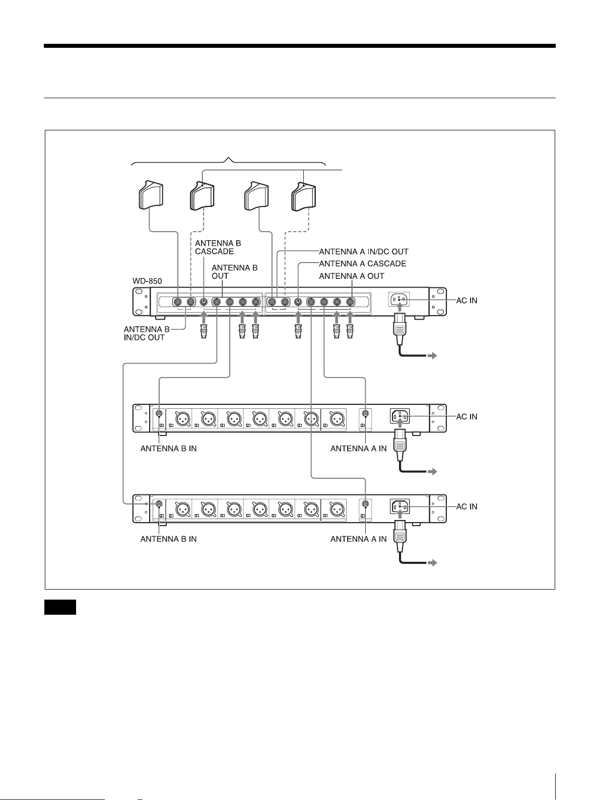
Connection
Example 1: When two MB-X6 or MB-806A units are connected
AN-820A
When four antennas are connected
50-ohm terminator
MB-X6 or MB-806A
MB-X6 or MB-806A
Notes
50-ohm terminator
• Connect the supplied 50-ohm terminator to any
ANTENNA A/B OUT connector or ANTENNA A/B
CASCADE connector that is unoccupied. Do not
connect the terminator to an unoccupied ANTENNA A/
B IN/DC OUT connector.
• 9V DC power for the booster amplifier of the AN-820A
UHF antenna is supplied from the ANTENNA A and B
IN/DC OUT connectors. Take care not to short-circuit
these connectors.
• Always use a pair of antennas (A and B).
50-ohm
terminator
To AC power source
To AC power source
To AC power source
Connection
9
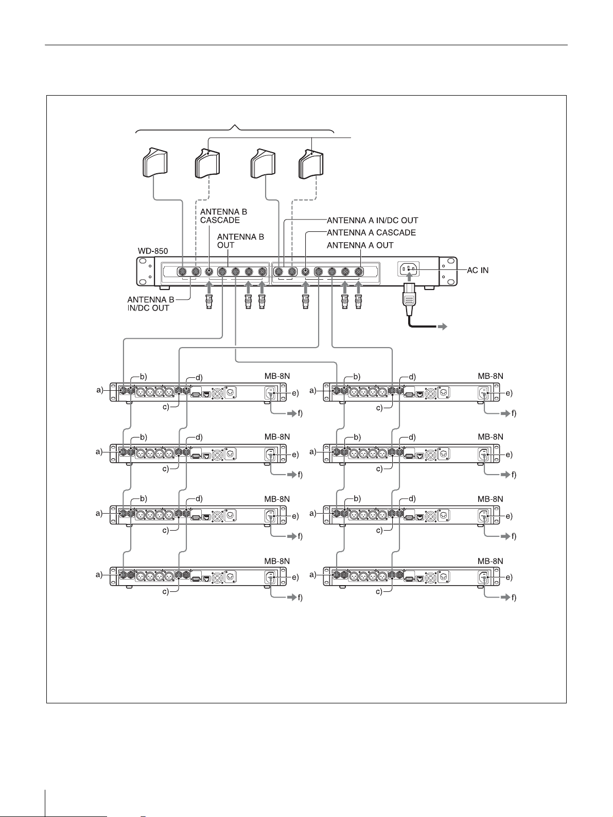
Example 2: When eight MB-8N units are connected (two directly and six
through cascade connections)
AN-820A
When four antennas are connected
50-ohm terminator
a) ANTENNA B IN
b) ANTENNA B OUT
c) ANTENNA A IN
d) ANTENNA A OUT
e) AC IN
f) To an AC power source
50-ohm terminator
50-ohm
terminator
To an AC power
source
10
Connection
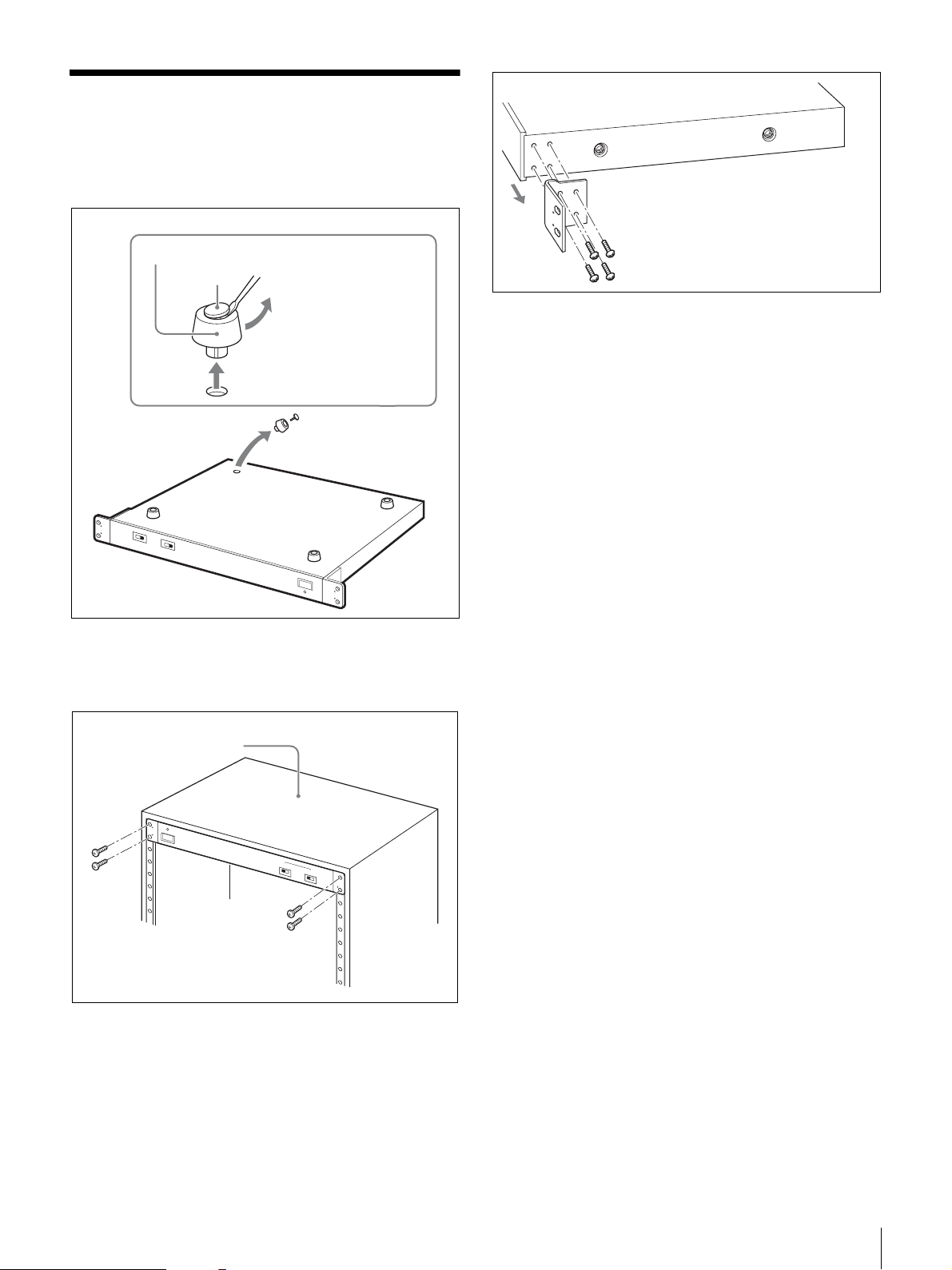
Rack-mounting the unit
1
Remove the four feet from the bottom of the unit in
advance.
Foot
Pin
Remove the pins inside the
feet with a small screwdriver
or similar tool.
Bottom panel
WD-850
2
Mount the unit on the rack using screws that are at
least 10 mm (
2
/5 in.) long and that match the diameter
of the screw holes on the rack.
Rack
WD-850
Screws
Removing the mounting brackets
You can remove the rack mounting brackets from the unit
if you do not intend to mount it in a rack.
Rack-mounting the unit
11
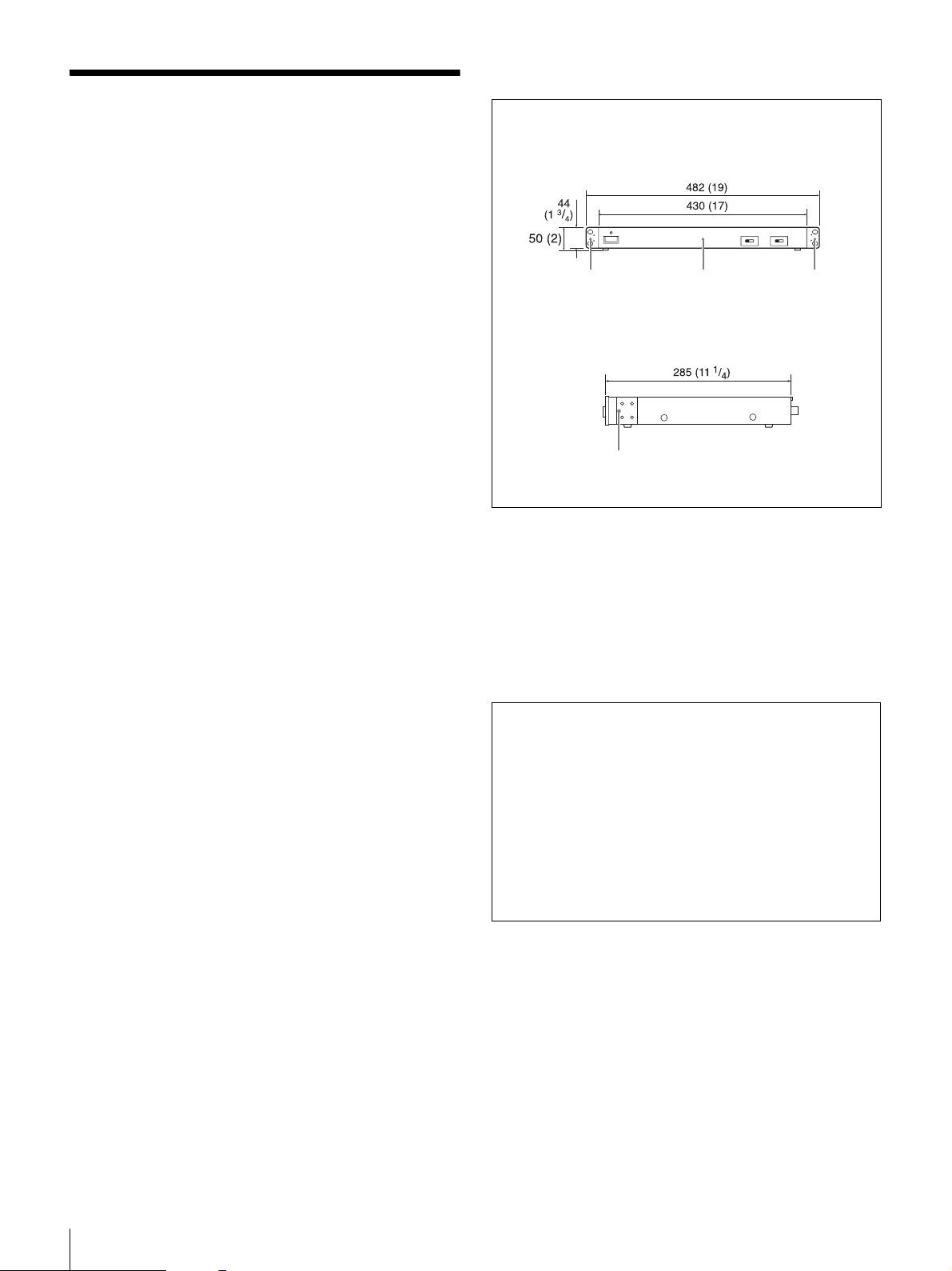
Dimensions
Specifications
Frequency range
US model: 566 to 806 MHz
European and Australian models: 566 to
862 MHz
Antenna input/output impedance
50 ohms
Antenna input/output connectors
BNC-R (BNC-BJ) type
Antenna input connectors
2 inputs 2 channels
Cascade output connectors
1 output 2 channels
Output connectors
4 output 2 channels
RF transmission loss
±3 dB (between antenna input to output)
Inter-connector connection loss
15 dB or more
Input/output VSWR
3.0 or less
Power requirements
US model: AC 120 V 60 Hz
European and Australian models: AC 230
V 50 Hz
Power consumption
18 W (when 100 mA is being supplied to
the antenna booster)
Power supply for antenna booster
DC 9V/OFF switchable (supplied
through the antenna input connectors)
Operating temperature
0°C to +50°C (+32°F to +122°F)
Storage temperature
–20°C to +60°C (–4°F to +140°F)
Unit: mm (inches)
Front view
Rack mounting
bracket
Side view
Rack mounting bracket
WD-850 Rack mounting
bracket
Mass Approx. 4.4 kg (9 lb 11 oz)
Accessories supplied
50-ohm terminator (6)
AC power cord (1)
Operating Instructions (1)
Design and specifications are subject to change without
notice.
Note
Always verify that the unit is operating properly before
use. SONY WILL NOT BE LIABLE FOR DAMAGES
OF ANY KIND INCLUDING, BUT NOT LIMITED
TO, COMPENSATION OR REIMBURSEMENT ON
ACCOUNT OF THE LOSS OF PRESENT OR
PROSPECTIVE PROFITS DUE TO FAILURE OF
THIS UNIT, EITHER DURING THE WARRANTY
PERIOD OR AFTER EXPIRATION OF THE
WARRANTY, OR FOR ANY OTHER REASON
WHATSOEVER.
12
Specifications
Français
AVERTISSEMENT
Afin de réduire les risques d’incendie ou
d’électrocution, ne pas exposer cet
appareil à la pluie ou à l’humidité.
Afin d’écarter tout risque d’électrocution,
garder le coffret fermé. Ne confier
l’entretien de l’appareil qu’à un personnel
qualifié.
CET APPAREIL DOIT ÊTRE RELIÉ À LA
TERRE.
ATTENTION
Eviter d’exposer l’appareil à un égouttement ou à des
éclaboussures. Ne placer aucun objet rempli de liquide,
comme un vase, sur l’appareil.
Pour les clients en Europe
Par la présente Sony Corporation déclare que l’appareil
WD-850 est conforme aux exigences essentielles et aux
autres dispositions pertinentes de la directive 1999/5/CE.
Pour toute information complémentaire, veuillez consulter
l’URL suivante: http://www.compliance.sony.de/
FR
13

Table des matières
Présentation...................................................................................15
Remarques importantes sur le fonctionnement .........................15
A propos de l’utilisation du câble coaxial........................................... 15
Conditions de fonctionnement............................................................. 15
Localisation et fonction des pièces.............................................16
Panneau avant...................................................................................... 16
Panneau arrière .................................................................................... 17
Connexion ......................................................................................18
Exemple 1 : Lorsque deux appareils MB-X6 ou MB-806A sont
Exemple 2 : Lorsque huit appareils MB-8N sont connectés (deux
Montage en rack de l’appareil ......................................................20
Spécifications ................................................................................21
connectés.................................................................................... 18
directement et six par connections cascade) .............................. 19
14
Table des matières

Présentation
Le WD-850 est un diviseur d’antenne UHF destiné à être
utilisé avec le système de microphone sans fil UHF de
Sony.
Remarques importantes
sur le fonctionnement
A propos de l’utilisation du câble
Sortie de signal d’antenne vers un
maximum de quatre récepteurs
Cet appareil est équipé d’un circuit diviseur à 2 canaux qui
permet d’envoyer les signaux d’antenne reçus de deux
antennes UHF AN-820A vers un maximum de quatre
récepteurs. Ceci permet de configurer facilement un
système de réception à canaux multiples en connectant des
syntoniseurs MB-X6/8N Sony ou un équipement similaire.
Connecteurs de sortie cascade permettant
l’utilisation simultanée d’un maximum de
deux diviseurs de canaux WD-850
La connexion des connecteurs cascade aux deux diviseurs
de canaux WD-850 active la sortie de signal vers un
maximum de huit syntoniseurs.
Connecteurs d’entrée d’antenne à 2
canaux
Cet appareil est muni de deux connecteurs pour chaque
canal. Le fait d’augmenter le nombre d’antennes à quatre
permet d’élargir la portée d’utilisation du microphone sans
fil.
coaxial
L’utilisation d’un câble coaxial 5D-2V ou supérieur (50
ohms) est recommandé pour la connexion des antennes au
syntoniseur ou diviseur d’antenne. Vous pouvez
également utiliser un câble 5C-2V ou supérieur (75 ohms).
Perte de signal : 5D-2V 50 m : 12,5 dB
100 m : 25 dB
5C-2V 50 m : 13,5 dB
100 m : 27 dB
Etant donné que la longueur du câble affecte davantage la
perte de signal que la différence de 50 à 75 ohms, le câble
doit être le plus court possible.
Conditions de fonctionnement
Utilisez à une température comprise entre 0 ºC et +50 ºC.
Alimentation fournie à l’antenne UHF
AN-820A
L’alimentation est fournie à l’amplificateur de puissance
de l’antenne UHF AN-820A. Les interférences ou les
distorsions de son peuvent s’éliminer facilement en
mettant hors tension l’amplificateur de puissance.
Montage en rack EIA 1U
L’appareil peut être monté dans un rack standard EIA de
19 pouces (1U).
Présentation / Remarques importantes sur le fonctionnement
15
 Loading...