

Sony WCS-999 Service manual
WCS-999
SERVICE MANUAL
Ver 1.0 1999. 09
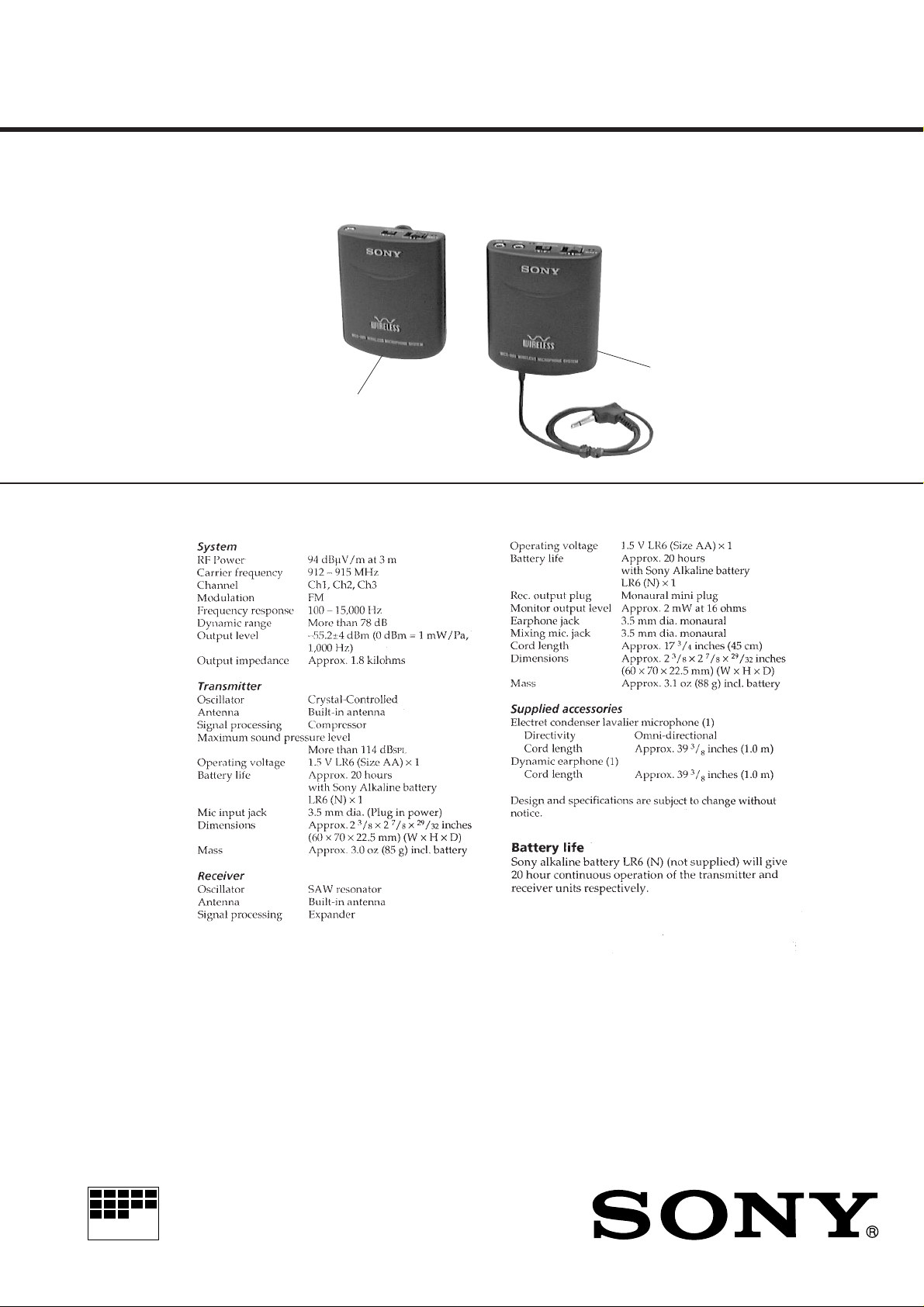
Transmitter
SPECIFICATIONS
US Model
Canadian Model
Receiver
MICROFILM
WIRELESS MICROPHONE SYSTEM

TABLE OF CONTENTS
1. GENERAL ............................................................ 3
2. DISASSEMBLY ......................................................... 4
3. ELECTRICAL ADJUSTMENTS
TX Section ...................................................................... 6
RX Section ...................................................................... 8
4. DIAGRAMS
4-1. Block Diagram – TX Section – ..................................... 9
4-2. Block Diagram – RX Section – ..................................... 11
4-3. Printed Wiring Boards – TX Section – .......................... 13
4-4. Schematic Diagram – TX Section – ............................... 15
4-5. Printed Wiring Boards – RX Section – ......................... 17
4-6. Schematic Diagram – RX Section – .............................. 19
5. EXPLODED VIEWS ................................................ 23
6. ELECTRICAL PARTS LIST ............................... 25
Notes on chip component replacement
• Never reuse a disconnected chip component.
• Notice that the minus side of a tantalum capacitor may be damaged by heat.
– 2 –
SECTION 1
GENERAL
This section is extracted from
instruction manual.
– 3 –
SECTION 2
)
h
DISASSEMBLY
Note: Follow the disassembly procedure in the numerical order given.
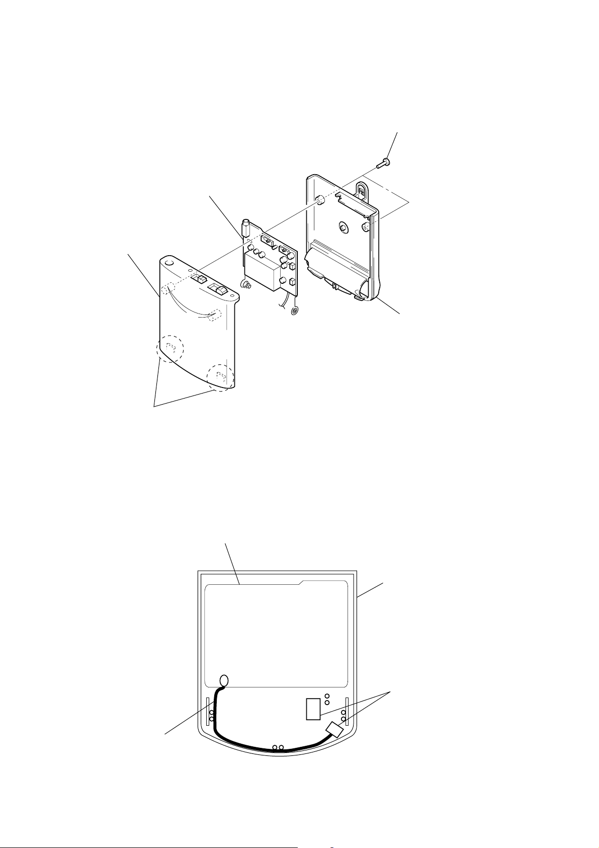
TX BOARD
4
TX board
3
case (upper)
1
two screws
(P2 × 6)
3
case (lower
2
ANTENNA SETTING
two claws
TX board
case (upper)
cushion (lower), switc
antenna
case (upper) rear view
– 4 –
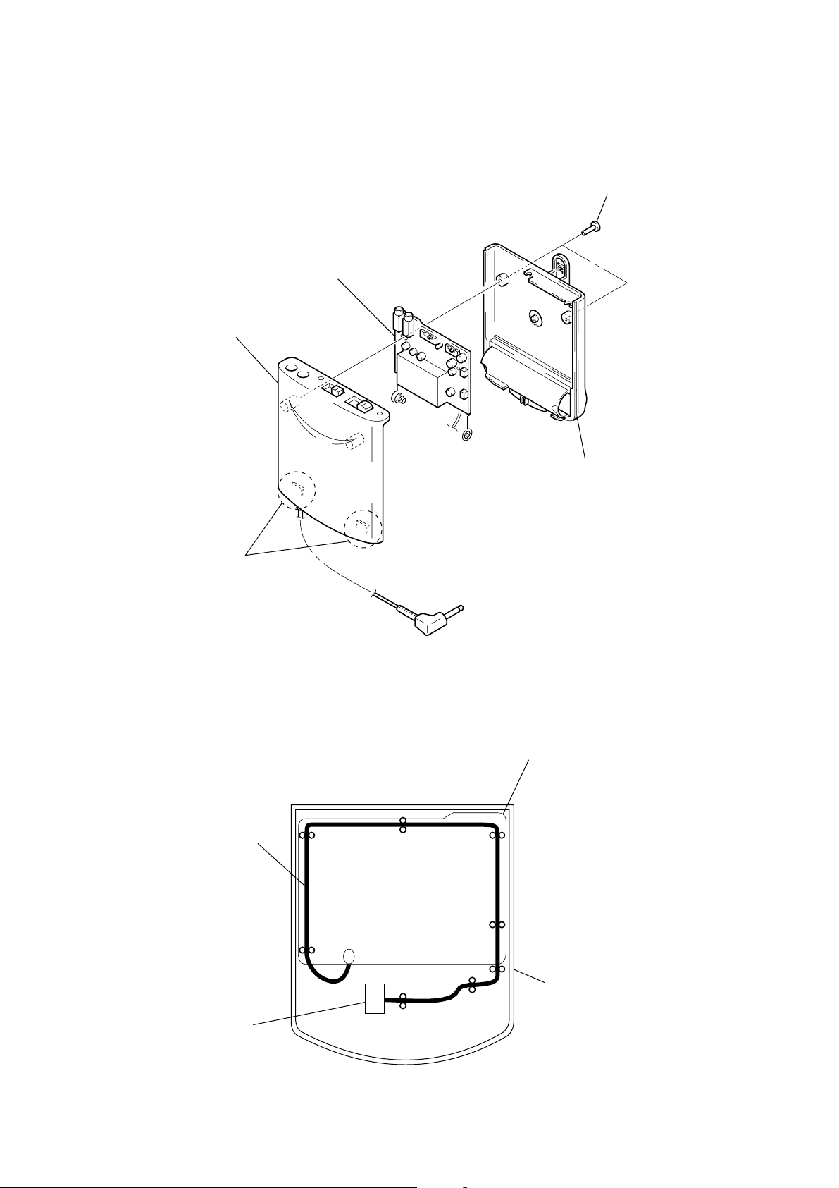
RX BOARD
)
3
case (upper)
4
RX board
3
case (lower)
1
two screws (P2 × 6)
2
two claws
ANTENNA SETTING
RX board
antenna
cushion (lower), switch
case (upper
case (upper) rear view
– 5 –
SECTION 3
r
ELECTRICAL ADJUSTMENTS
Note: Tool
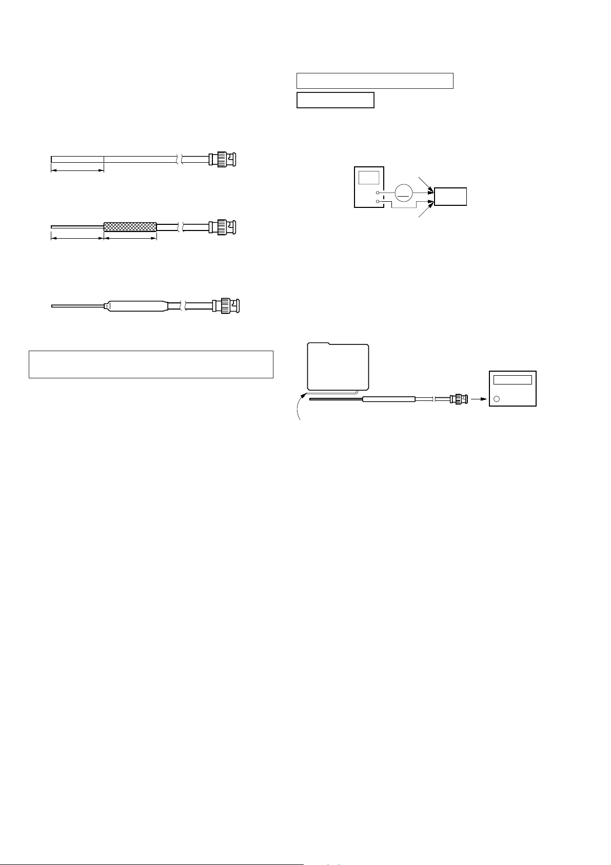
• 1/4 λ sleeve antenna
Production procedure:
1. Cut about 80 mm of the outer cover at the other end of an
approximately 2 meter coaxial cable (1.5D-2V or the equivalent) with a BNC connector.
80 mm
BNC
2. Pull back the outer co ver and fold the wire mesh over the outside cover.
80 mm
80 mm
BNC
3. Co ver the folded back wire mesh (outer cov er) with a tube (for
example, heat shrink tube) and fasten.
BNC
The WCS-999 is a wireless microphone system operating in the 900
MHz. This system comprises the transmitter unit and the receiver unit.
0 dBm = 1 mW, 0 dBV = 1 Vrms
TX SECTION
1. Consumption Current Check
Setting:
regulated dc
power supply
+
–
Procedure:
1. Connect a regulated dc po wer supply (1.5 V) and amper e meter.
2. Check that the value of ampere meter satisfy specified value.
Specified value: 70 mA to 80 mA
2. TX Frequency Confirmation
Setting:
TX BASE
board
battery
terminal
mA
battery
terminal
3
Set
#
frequency counte
λ
sleeve antenna
1/4
lead wire antenna (ANT1)
Procedure:
1. Connect the 1/4 λ sleeve antenna to a frequency counter, and
put the antenna by the lead wire antenna (ANT1).
2. Set the [RF CHANNEL] switch (SW51) to[1].
3. Confirm that the value of frequency counter satisfy specified
value.
4. Change the [RF CHANNEL] switch (SW51) to [2].
5. Confirm that the value of frequency counter satisfy specified
value.
6. Change the [RF CHANNEL] switch (SW51) to [3].
7. Confirm that the value of frequency counter satisfy specified
value.
Specified values: CH-1: 912.78 MHz to 912.92 MHz
CH-2: 913.68 MHz to 913.82 MHz
CH-3: 914.28 MHz to 914.42 MHz
– 6 –
 Loading...